
 Open Access Article
 This Open Access Article is licensed under a
 Creative Commons Attribution 3.0 Unported Licence
Reversible control of the magnetization of Fe3O4 via lithium ions
Guodong Weia,
Lin Weib,
Dong Wanga,
Yufeng Tiana,
Yanxue Chen *a,
Shishen Yana,
Liangmo Meia and
Jun Jiaoc
*a,
Shishen Yana,
Liangmo Meia and
Jun Jiaoc
aSchool of Physics and State Key Laboratory of Crystal Materials, Shandong University, Jinan 250100, P. R. China. E-mail: cyx@sdu.edu.cn
bSchool of Microelectronics, Shandong University, Jinan 250100, P. R. China
cDepartment of Mechanical and Materials Engineering, Portland State University, Post Office Box 751, Portland, Oregon 97207-0751, USA
First published on 12th January 2017
Abstract
In this report, a reversible control of Fe3O4 saturated magnetization by Li ions is demonstrated. A miniature Li ion battery (LIB) was assembled using a Fe3O4 nanoparticle layer as the active cathode. A stable magnetism modulation is realized by a nondestructive electrochemical process in which the lithium insertion results in a valence change and partial redistribution of Fe cations in the crystal structure. The relation between the discharge voltage and the chemical phases were studied by ex situ X-ray diffraction and magnetic measurement. In a suitable discharge potential range, a reversible control of Fe3O4 saturated magnetization was obtained without structural damage to the magnetic electrode. The experimental results indicate by further optimizing the LIB's performance, a large reversible change in magnetization could be realized at room temperature, suggesting the potential for future practical applications.
1 Introduction
Electric-field control of magnetization has attracted intensive research interests in recent years for its potential applications in magnetic memory storage, sensors, and spintronics.1–3 Both magnetic control of ferroelectric polarization and electric control of magnetization have been demonstrated in some artificially structured composites by a variety of methods.4 However, traditional electric control methods generally operate in a few atomic layers adjacent to the surface or the interface, and conventional magnetoelectric couplings are weak in most cases. For many practical applications, a larger magnitude of magnetic response is required. As a result, various efforts have been made to find an alternative approach to improve effectiveness. For example, the magnetic properties could be reversibly tuned by the electrochemical double layer in ion electrolyte gated devices.5–9 When high surface area materials were used, large change in magnetism was obtained.10 The approach uses electrochemical ion insertion/extraction for bulk materials.The electrochemical control of magnetism has been intensively investigated in metal–organic frameworks with multiple functionalities. Magnetism switching has been demonstrated by electrochemical Li ion insertion/extraction in bimetallic prussian blue analogues.11–13 Recently, researchers have also focused on the coexistence of magnetism and ion storage ability in transition metal oxides, which have been widely explored for high-performance lithium ion batteries.14 It is worth noting that the redox states of these materials can be controlled by the electrochemical process. Since the variation of the valence state in transition metal oxides may alter the magnetically related d orbital electrons, a reversible control of magnetism could be realized if the charge/discharge voltage range is carefully set.15–20 This brilliant feature, advanced by the rapid development of lithium battery manufacturing technique, makes it also a promising approach to achieve the magnetic modulation of material properties.
In this work, we report the in situ observation of magnetic response of Fe3O4 during the inserting/extracting of Li ions using a miniature lithium-ion-battery (LIB) cell. As the storage of lithium is a bulk behaviour in Fe3O4 material, this magnetic response to electrical stimulus could go beyond the surface reaching a large change magnitude. With a charging current density of 60 mA g−1, the cycling time is only 10 min, which could be further reduced if a higher current density is applied. During the charging/discharging process, a reversible magnetism change was detected. The nondestructive magnetic modulating process, the fast response speed and the simple fabrication process, make this LIB-based device a promising candidate for future practical applications such as micro-magnetic actuation.
2 Experimental
2.1 Electrode preparation and cell fabrication
Commercial Fe3O4 nanoparticles with average size of 20 nm (Aladdin Industrial Co.) were adopted to prepare the electrodes. 80 wt% active materials, 10 wt% acetylene black, and 10 wt% polyvinylidene fluoride (PVDF) binder were mixed and dispersed in N-methyl pyrrolidinone (NMP). The slurry was spread onto a copper foil current collector. It was then dried in a chamber electric furnace at 70 °C for 10 hours to form a working electrode. The miniature Li battery cells were assembled into a small glass vial with lithium metal as the counter electrode. A Celgard2325 microporous polypropylene membrane was used as separator. The electrolyte (LBC3015B) used for the experiments was purchased from Shenyang Kejing Auto-instrument Co. The entire assembling process was carried out inside an argon-filled glove box.2.2 Characterization
The crystal phase of the samples was examined by X-ray diffraction (XRD). Charge/discharge experiments were tested using a CT2001A cell test instrument (LAND Electronic Co.). An electrochemical workstation (RST5202) was used to study the cyclic voltammetry (CV) performance in the potential range of 0.01–3.0 V at a scan rate of 0.1 mV s−1 and 50 mV s−1. The ex situ magnetic measurement was carried out at room temperature using an alternating grating gradient magnetometer (AGM). The as-prepared working electrode and the electrodes collected at different discharge voltage after being washed in dimethyl carbonate (DMC) were measured. The in situ magnetic measurements were performed simultaneously with the discharging/charging processes in a Quantum Design superconducting quantum interference device (SQUID) magnetometer.3 Results and discussion
3.1 Structural and electrochemical characterization
Fig. 1 shows the schematic diagram of the LIB configuration. A small glass vial was chosen to hold the electrolyte since it exhibits low magnetic susceptibility and high homogeneity. A chemically resistant epoxy resin was used to seal the device provided with two feedthroughs for the enamel covered wire connecting the Li anode and the strip type copper foil coated with the Fe3O4 nanoparticles. | ||
| Fig. 1 Schematic of the lithium-battery cell for in situ measurements. | ||
The entire electrochemical reactions during the intercalation/de-intercalation process can be described in the following three steps:
At discharge stage:
| Fe3O4 + 2Li+ + 2e− → Li2(Fe3O4) | (1) |
| Li2(Fe3O4) + 6Li+ + 6e− → 3Fe + 4Li2O | (2) |
At charge stage:
| 3Fe + 4Li2O → Fe3O4 + 8Li+ + 8e− | (3) |
It has been reported that before the first step is accomplished, there is a discharge procedure in which the reduction is a non-destructive electrochemical process. This means that Li+ can be inserted into the Fe3O4 lattice while maintaining its intact spinel crystal structure.21,22 The reversible modulation of the magnetism transpires in this step. With further lithiation, the structure will change into rocksalt-type and the decreased magnetism will be unrecoverable by de-lithiation. An abundance of literature indicates that this irreversible structure change is related to the discharge plateau of Fe3O4 around 0.8 V (vs. Li+/Li).23–27 This is also confirmed in our experiments.
To reveal the relation between the structure of the cathode material and the discharge voltage, ex situ XRD characterization is conducted. Fig. 2 shows the ex situ XRD results of the cathode material at different discharge stages. The characteristic peaks of Fe3O4 and Li2(Fe3O4), as well as the peaks introduced by Cu foil and Al holder are respectively marked in the picture. Compared with the as-prepared Fe3O4, the working cathode could maintain its spinel structure as long as the discharge voltage is higher than 0.8 V. However, after the cell is discharged to 0.7 V, it was found that the diffraction peaks of spinel structures transfer to a rock-salt structure as a consequence of Li insertion, which indicates that Fe3O4 turns into Li2(Fe3O4) at this voltage.
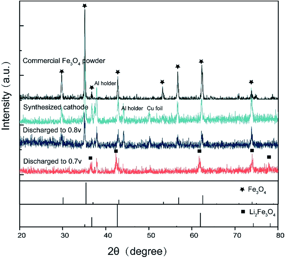 | ||
| Fig. 2 XRD results of different discharge stage. The material maintains its spinel structure until it is discharged to 0.8 V, but transfers to rock-salt Li2(Fe3O4) at 0.7 V. | ||
Fig. 3a shows the charge/discharge curves for the first ten cycles between 0.8 and 3.00 V. It can be seen that the sample preforms a high lithium storage capacity during the initial discharge process, but an obvious decay occurs at this point. At first sight, these capacity decay features are unlikely due to electrolyte decomposition at the surface of the material, as they are mainly observed within the stability window of the presently used solvent. The decay is likely due to the reduction of surface functional groups, and could also be ascribed to an electrochemical grinding of the particles as a result of internal strains or a second phase formation caused by some side reactions, as proved by the decreased intensity of XRD peaks. However, the following cycles show a highly improved stability, which implies a factor most likely safeguarded the subsequent reactions, whose effect is similar to SEI layers, known to be formed below 1.0 V vs. Li+/Li. Fig. 3b shows the cyclic voltammetry (CV) curves between 0.01 and 3.0 V at a scan rate of 0.1 mV s−1. As shown, the reversible discharge plateau ends at 0.8 V, followed by a sharp decrease towards the cutoff voltage of 0.01 V. The cathodic peak at 0.5 V can be attributed to the reduction of Li2(Fe3O4) to Fe. The 0.8 V inflection point agrees perfectly with the structure change observed in the XRD results. The inset gives the CV curves under a quick scan rate of 50 mV s−1, exhibiting an extraordinarily stable capability, most likely due to the small particle size (20 nm), which benefits the charge-transfer reaction rate and buffers the volume expansion during high current charging/discharging processes. This feature is significant because it shows this cell can work under a fast charge/discharge routine.
 | ||
| Fig. 3 (a) The first ten discharge/charge voltage profiles of Fe3O4 with a constant current density of 60 mA g−1 between 0.8 and 3.0 V. (b) Cyclic voltammetry (CV) curves of the Fe3O4 composite electrode between 0.01 and 3.0 V at a scan rate of 0.1 mV s−1. The inset gives the outcome at 50 mV s−1. | ||
3.2 Magnetic measurements
The magnetic modulation is studied first by analysing ex situ magnetic hysteresis loops, obtained using an alternating grating gradient magnetometer. As shown in Fig. 4, the saturated magnetisation value decreases from 71.7 emu g−1 to 63.8 emu g−1 as the device is discharged from the as-prepared state to that of operated at 0.8 V. It was speculated that the amount of Li able to be inserted into transition metal oxides before the phase transition occurs is closely related to the morphology and size of the particles. For example, up to one Li per formula unit can be inserted into nanosize Fe2O3 without phase transformation at the early stage of the reduction, while less than 0.1 Li per formula unit insertion could change the structural transfer to rock-salt compound for 0.5 μm Fe2O3.28 However, it is difficult to tell whether or not small structural changes are contributing to the magnetic variation in this range. In addition, simple electrochemical reduction models of magnetic cations can only explain a nominal fraction of the total magnetization variation. There could also be changes in g-factors or exchange coupling constants. As a result, conducting quantitative comparisons between the magnetic moment change and Li insertion amount is still a challenging task. Nevertheless, a specific magnetic variation can be seen with Li insertion. As the cell is further discharged from 0.8 V to 0.7 V, a much larger magnetism decrease is observed, which might be caused by the formation of paramagnetic Li2(Fe3O4).21 The loop of 0.7 V still shows some hysteresis behaviour. It might be originated from remaining Fe3O4 that has not been converted yet. It is reasonable to speculate that an enhancement of magnetism might be achieved in the electrochemical process of Li2(Fe3O4) reducing to Fe particles.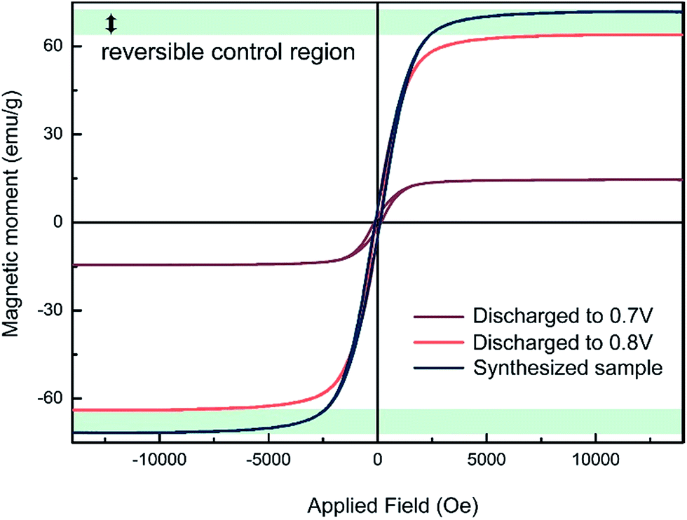 | ||
| Fig. 4 The ex situ magnetic hysteresis measurement results at different discharge voltage. The maximum range of the possible reversible magnetic variation has been marked in this figure. | ||
To verify if the magnetism can be controlled reversibly by an applied voltage, the LIB was loaded into a superconducting quantum interference device magnetometer to carry out the in situ saturation magnetization measurement with 1 T field applied to the sample. Magnetic moment is recorded every 5 seconds under a current density of 60 mA g−1 galvanostatical discharge and charge cycle. As shown in Fig. 5, the magnetization variation trend keeps pace exactly with the galvanostatically discharge and charge process. The cycle time is about 600 s, meaning it takes only 5 minutes for the magnetism to vary from maximum to minimum value. As mentioned above, an obvious capacity decrease has been observed in the first cycle, accompanied by a decrease of the magnetism variation range. As the capacity becomes stable after the first cycle, the magnetism variation also stabilizes. This suggests that reducing the amount of working Li ions involved in the electrochemical process may be responsible for the low magnetization changes. Some irreversible reactions could happen in this process. The same procedure is also performed under lower current densities (1C). At the same voltage rage, the first cycle capacity decrease was still observed. This may be attributed to the cause by some phase change side reactions. Under the same experimental conditions, the cell was tested 10 cycles and adjusted to a stable state before loaded into SQUID. The results (Fig. 5) show that the magnetic variation is much smaller than that in Fig. 4. In the mean time, it demonstrates a thoroughly reversible modulation. This result is consistent with those in the literature where the modulation rate has reached more than 10%, with a small-applied field of 100 Oe and higher voltage range.16 Different experimental circumstances might affect the result, but it is reasonable to believe that if the capacity reduction can be controlled and optimized, larger magnetism modulation ratio should be expected.
 | ||
| Fig. 5 The in situ magnetic measurements performed simultaneously with the electrochemical discharging/charging processes. In the range from 3 to 0.8 V, the saturation magnetization of Fe3O4 reversibly changes from 70.2 emu g−1 to 69.5 emu g−1 in about 5 minutes. | ||
We also performed an in situ nonlinear charge test to study the cell's real-time response with the applied electrical voltage (Fig. 6). The battery is first discharged to 0.8 V, then charged up to a step voltage with a constant-current of 0.2 A, following a constant-voltage charge process until the current is less than 20 μA, with a long pause of 5 minutes before moving to the next charge step. The step voltage is set to be 1.5 V, 2.0 V, 2.5 V and 3.0 V respectively. As illustrated in Fig. 6, when a larger step voltage is applied, the magnetism changes responded with a faster speed. The responding curves in Fig. 6 also indicate that it is quite stable on the steps and varies rapidly on the edges. This suggests that the voltage can control the magnetism effectively. From these results we can also conclude that the capacity, symbol of the insertion Li amount, is positively related to the magnetic moment.
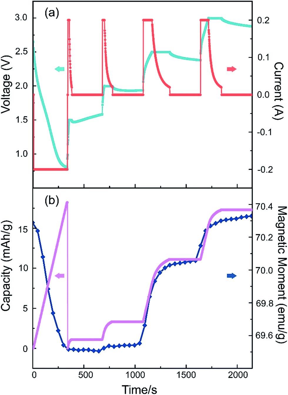 | ||
| Fig. 6 The cell's real-time response with the applied electrical voltage. (a) The current and voltage settings during the charge test. (b) The magnetic moment and capacity change profiles in this process. | ||
3.3 Explanation of the magnetic and electrochemical process
It is well-known that the super exchange interaction dominates the magnetism in spinel type oxides, in which the exchange constant J is sensitive to the angle between the transition metal atoms. Magnetite is one of the most studied spinel material. It crystallizes in a cubic closed packed structure formed by oxygen atoms consisting of 32 octahedral and 64 tetrahedral sites, with metal ions occupying the interstices between the oxygen ions. In the case of Fe3O4, A-sites neighboured by an oxygen tetrahedron are occupied by Fe3+, and half of the B-sites in the center of an oxygen octahedron are filled with Fe2+ and half with Fe3+. As the other interstitial sites in the framework of the spinel structure are left unoccupied, it is a natural material for Li insertion. Here, an assumption is made based on the Neel linear model, a simplified magnetic structure widely utilized to explain the coupling in spinel ferrites. Although the model is less accurate, it could make a general description of the interactions between the magnetic cations. As shown in Fig. 7, when Li ions are inserted into the Fe3O4 crystal structure, the reduction of ferric ions could cause either an increase or decrease of the magnetism. If the reduction happens in the A site (Fig. 7b), the net magnetic moment would increase. If the reduction happens in the B site (Fig. 7c), it would cause a decrease of the magnetic moment. In our in situ magnetic measurement, the second process overwhelms the first one, meaning the chemical reduction of the octahedral Fe3+ to Fe2+ dominates the overall magnetic response. As reported,29 the interaction of lithium with Fe3+ would also cause the A-sites Fe3+ to displace to empty neighbor 16c sites. When the insertion amount is small, it may cause a rise of magnetism. However, in our experiment, this increase was not observed, probably due to the fast charge/discharge process and inhomogeneous reaction in the electrode. Changes in exchange coupling constant or Curie temperature could also influence the result. Future work will be conducted to understand its exact origin of this magnetism modulation. | ||
| Fig. 7 Schematic view of the magnetic moments at the Fe (A) and (B) sublattices: (a) magnetite, (b) Fe3+ ions at the octahedral A sites reduced to Fe2+ ions, (c) Fe3+ ions at the tetrahedral B sites reduced to Fe2+ ions. | ||
4 Conclusions
In summary, a miniature Li ion battery was assembled with Fe3O4 as the active cathode, providing a strategy for electric-field control of magnetization via the Li ion inserting/extracting process. The XRD and CV measurements were combined to determine the suitable discharge potential range that would allow maximum lithium insertion and avoid structural damage to the magnetic electrode. In the range from 3 to 0.8 V, the saturation magnetization of Fe3O4 changes reversibly from 70.2 emu g−1 to 69.5 emu g−1 in about 5 minutes. A simple model was suggested to explain the modulating process. It is foreseeable that by surface modification or synthesizing various nanostructures of the active material to enhance Li (or other) ion diffusion, it is possible to gain a faster modulation rate with a large magnetism change. This would be very promising for many practical applications.Acknowledgements
This work was supported by the National Key Research and Development Program of China (2013CB922303, 2016YFA0301204), the National Natural Science Foundation of China (11274201, 51231007), the 111 Project (B13029), and the Fundamental Research Funds of Shandong University (2014YQ003).References
- D. Chiba, S. Fukami, K. Shimamura, N. Ishiwata, K. Kobayashi and T. Ono, Nat. Mater., 2011, 10, 853–856 CrossRef CAS PubMed.
- H. J. A. Molegraaf, J. Hoffman, C. A. F. Vaz, S. Gariglio, D. van der Marel, C. H. Ahn and J.-M. Triscone, Adv. Mater., 2009, 21, 3470–3474 CrossRef CAS.
- F. Xiu, Y. Wang, J. Kim, A. Hong, J. Tang, A. P. Jacob, J. Zou and K. L. Wang, Nat. Mater., 2010, 9, 337–344 CrossRef CAS PubMed.
- C. A. Vaz, J. Hoffman, C. H. Ahn and R. Ramesh, Adv. Mater., 2010, 22, 2900–2918 CrossRef CAS PubMed.
- T. D. Schladt, T. Graf, N. B. Aetukuri, M. Li, A. Fantini, X. Jiang, M. G. Samant and S. S. P. Parkin, ACS Nano, 2013, 7, 8074–8081 CrossRef CAS PubMed.
- K. Fujiwara, T. Ichimura and H. Tanaka, Adv. Mater. Interfaces, 2014, 1, 13000108 Search PubMed.
- H. T. Yi, B. Gao, W. Xie, S. W. Cheong and V. Podzorov, Sci. Rep., 2014, 4, 6604 CrossRef CAS PubMed.
- M. Weisheit, S. Fahler, A. Marty, Y. Souche, C. Poinsignon and D. Givord, Science, 2007, 315, 349–351 CrossRef CAS PubMed.
- Y. Yamada, K. Ueno, T. Fukumura, H. T. Yuan, H. Shimotani, Y. Iwasa, L. Gu, S. Tsukimoto, Y. Ikuhara and M. Kawasaki, Science, 2011, 332, 1065–1067 CrossRef CAS PubMed.
- C. Reitz, P. M. Leufke, R. Schneider, H. Hahn and T. Brezesinski, Chem. Mater., 2014, 26, 5745–5751 CrossRef CAS.
- Y. Mizuno, M. Okubo, K. Kagesawa, D. Asakura, T. Kudo, H. Zhou, K. Oh-ishi, A. Okazawa and N. Kojima, Inorg. Chem., 2012, 51, 10311–10316 CrossRef CAS PubMed.
- M. Okubo, D. Asakura, Y. Mizuno, T. Kudo, H. Zhou, A. Okazawa, N. Kojima, K. Ikedo, T. Mizokawa and I. Honma, Angew. Chem., Int. Ed., 2011, 50, 6269–6273 CrossRef CAS PubMed.
- O. Sato, J. Solid State Electrochem., 2006, 11, 773–779 CrossRef.
- P. Poizot, S. Laruelle, S. Grugeon, L. Dupont and J.-M. Tarascon, Nature, 2000, 407, 496–499 CrossRef CAS PubMed.
- S. Dasgupta, B. Das, M. Knapp, R. A. Brand, H. Ehrenberg, R. Kruk and H. Hahn, Adv. Mater., 2014, 26, 4639–4644 CrossRef CAS PubMed.
- T. Yamada, K. Morita, K. Kume, H. Yoshikawa and K. Awaga, J. Mater. Chem. C, 2014, 2, 5183 RSC.
- C. Reitz, C. Suchomski, D. Wang, H. Hahn and T. Brezesinski, J. Mater. Chem. C, 2016, 4, 8889–8896 RSC.
- Q. Zhang, X. Luo, L. Wang, L. Zhang, B. Khalid, J. Gong and H. Wu, Nano Lett., 2016, 16, 583–587 CrossRef CAS PubMed.
- S. Dasgupta, B. Das, Q. Li, D. Wang, T. T. Baby, S. Indris, M. Knapp, H. Ehrenberg, K. Fink, R. Kruk and H. Hahn, Adv. Funct. Mater., 2016, 26, 7507–7515 CrossRef CAS.
- X. Zhu, J. Zhou, L. Chen, S. Guo, G. Liu, R. W. Li and W. D. Lu, Adv. Mater., 2016, 28, 7658–7665 CrossRef CAS PubMed.
- P. H. Domingues, J. M. Neto, M. R. Silva and M. E. Massalami, Hyperfine Interact., 2001, 133, 41–46 CrossRef CAS.
- L. Gao, R. Li and Q. Chen, J. Phys. D: Appl. Phys., 2012, 45, 335001 CrossRef.
- C. He, S. Wu, N. Zhao, C. Shi, E. Liu and J. Li, ACS Nano, 2014, 7, 4459–4469 CrossRef PubMed.
- W.-M. Zhang, X.-L. Wu, J.-S. Hu, Y.-G. Guo and L.-J. Wan, Adv. Funct. Mater., 2008, 18, 3941–3946 CrossRef CAS.
- G. Zhou, D.-W. Wang, F. Li, L. Zhang, N. Li, Z.-S. Wu, L. Wen, G. Q. Lu and H.-M. Cheng, Chem. Mater., 2010, 22, 5306–5313 CrossRef CAS.
- P. Lv, H. Zhao, Z. Zeng, J. Wang, T. Zhang and X. Li, J. Power Sources, 2014, 259, 92–97 CrossRef CAS.
- J. Yin, H. Shi, P. Wu, Q. Zhu, H. Wang, Y. Tang, Y. Zhou and T. Lu, New J. Chem., 2014, 38, 4036 RSC.
- D. Larcher, C. Masquelier, D. Bonnin, Y. Chabre, V. Masson, J. B. Leriche and J. M. Tarascon, J. Electrochem. Soc., 2003, 150, A133 CrossRef CAS.
- J. M. N. P. H. Domingues, M. R. Silva and M. Elmassalami, Hyperfine Interact., 2001, 133, 41–46 CrossRef.
| This journal is © The Royal Society of Chemistry 2017 |