
Direct-growth carbon nanotubes on 3D structural microelectrodes for electrophysiological recording†
Alice Ian
Pan
a,
Min-Hsuan
Lin
b,
Hui-Wen
Chung
b,
Hsin
Chen
c,
Shih-Rung
Yeh
b,
Yung-Jen
Chuang
b,
Yen-Chung
Chang
b and
Tri-Rung
Yew
*a
aDepartment of Materials Science and Engineering, National Tsing Hua University, Hsinchu 30013, Taiwan. E-mail: tryew@mx.nthu.edu.tw; Fax: +886-3-5722366; Tel: +886-9-36347230
bDepartment of Life Sciences, National Tsing Hua University, Hsinchu 30013, Taiwan
cInstitute of Electronics Engineering, National Tsing Hua University, Hsinchu 30013, Taiwan
First published on 9th November 2015
Abstract
A novel 3D carbon nanotube (CNT) microelectrode was developed through direct growth of CNTs on a gold pin-shaped 3D microelectrode at a low temperature (400 °C) for applications in neural and cardiac recording. With an electroplated Ni catalyst layer covering the entire surface of the pin-shaped structure, CNTs were synthesized on a 3D microelectrode by catalytic thermal chemical vapor deposition (CVD). According to the analyses by electrochemical impedance spectroscopy, the impedance of 3D microelectrodes after CNT growth and UV/O3 treatment decreased from 9.3 Ω mm−2 to 1.2 Ω mm−2 and the capacitance increased largely from 2.2 mF cm−2 to 73.3 mF cm−2. The existence of UVO3-treated CNT led to a large improvement of interfacial capacitance, contributing to the decrease of impedance. The electrophysiological detection capability of this 3D CNT microelectrode was demonstrated by the distinguished P waves, QRS complex and T waves in the electrocardiogram of the zebrafish heart and the action potential recorded from individual rat hippocampal neurons. The compatibility of integration with ICs, high resolution in space, electrophysiological signals, and non-invasive long-term recording suggest that the 3D CNT microelectrode exhibits promising potential for applications in electrophysiological research and clinical trials.
Introduction
Bioelectric signals were studied to investigate the physiological and pathological functions of neural and cardiac systems and to develop treatment and medicine for diseases. The goal of electrophysiological technologies is to achieve long-term recording with high resolution of signal detection. At present, non-invasive extracellular microelectrode arrays (MEAs) have been extensively utilized for long-term and real-time recording, nevertheless suffering from low signal-to-noise ratio (SNR) and spatial resolution. To improve the detection resolution, researchers fabricated nano- and micro-structural MEAs to not only scale down the electrode size, but also increase the electrode surface area.1–3 3D structures such as nanoflakes,4 nanopillars,5 cones6 and mushrooms7,8 were used, leading to the decrease of electrode impedance and improvement of signal resolution. On the other hand, carbon nanotubes (CNTs) with intrinsically large surface areas,9,10 superior capacitive coupling,11 great biocompatibility12 and chemical inertia13 have become an attractive material for bio-electronic interfaces. By synthesizing CNTs on the 3D structural electrode, the nanostructure of CNTs further boosts the effective interfacial area. Moreover, the high capacitance of CNTs promotes the electrophysiological signal transfer.14,15 The advantages of CNTs on electrodes provide a promising and enhanced interface for neural and cardiac recording. In this study, a microstructural electrode with an enhanced interface is proposed for electrophysiological applications. Through direct growth of CNTs on pin-shaped 3D electrodes, 3D CNT electrodes were developed. The electrical properties of 3D CNT electrodes were studied and the functionality was demonstrated by distinct ECG waves of zebrafish and action potentials of rat hippocampal neurons.Experimental methods
The design of the chip for neural and cardiac recording is shown in Fig. 1a. It was composed of 3 × 3 3D CNT electrode arrays (Fig. 1b), interconnects and readout pads.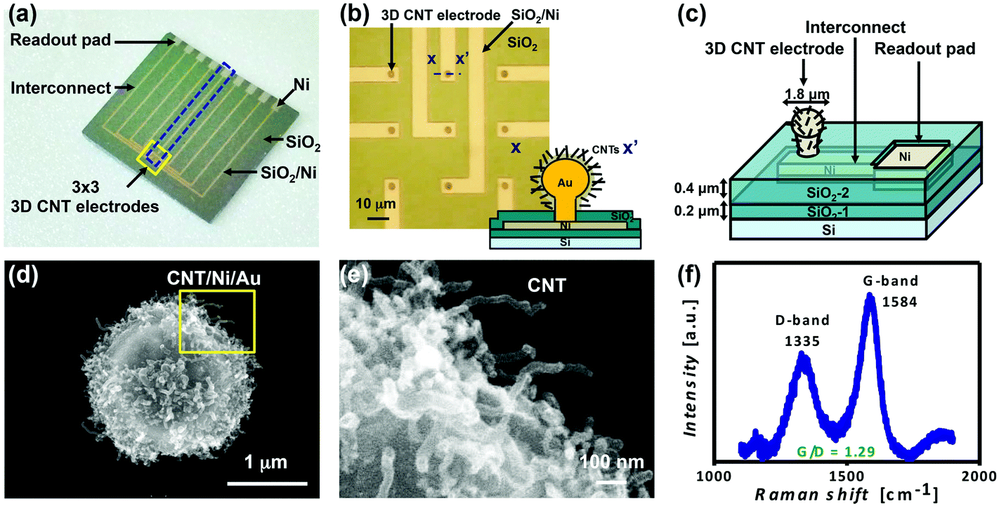 | ||
| Fig. 1 (a) The photograph of a 3D CNT electrode chip. (b) The optical micrograph of 3 × 3 3D CNT electrode arrays from the boxed area in (a) and a cross-sectional scheme from the dashed line x–x′ on the bottom right corner. (c) The 3D schematic of a single electrode device from the blue dashed area in (a). The SEM images of (d) a 3D CNT electrode and (e) the CNTs taken from the yellow-boxed area of (d). (f) The micro-Raman spectra of the 3D CNT electrode. | ||
Fabrication of 3D CNT electrodes
The fabrication processes were briefly described as follows and illustrated in more detail in the ESI (Fig. A.1†). First, the pin-shaped gold structure (the 3D electrode) was formed by semiconductor processing and electroplating. With electroplated Ni as a catalyst layer covering the entire surface of the structure, CNTs were directly grown by chemical vapor deposition (CVD) at 400 °C to obtain 3D CNT electrodes as shown in Fig. 1c. Afterward, the 3D CNT electrodes were exposed to UV/O3 treatment for 40 min, called 3D UVO3-CNT electrodes, for CNT surface modification to form carbon–oxygen bonds and to anchor H2O molecules via intermolecular bonding, providing improved CNT/electrolyte interfacial contact and reaction.16Electrochemical characterization
The interfacial properties between the electrode and electrolyte determine the performance of the electrophysiological electrode, which could be analyzed by electrochemical impedance spectroscopy (EIS). The electrochemical measurements of 3D electrodes, 3D CNT electrodes and 3D UVO3-CNT electrodes were carried out in phosphate buffered saline (PBS, pH = 7.4). An Ag/AgCl coil was used as a reference and counter electrode with a structural microelectrode sample as a working electrode. Potentio-electrochemical impedance spectroscopy was performed by applying a 10 mV sinusoidal signal with various frequencies in the range of 20 Hz–10 kHz to characterize the electrode/electrolyte interface impedance. The EIS measurements were conducted with one electrode chip (9 microelectrodes at the same time) and the results were normalized with the surface area during analyses. To further study the influences of CNTs and UV/O3 treatment on the interface, the results of EIS measurements were fitted into equivalent circuit models of interfacial electrochemistry by EC-lab.Electrophysiological signal recording
Zebrafish is a widely used vertebrate model for the study of cardiovascular development and disease. In this study, the zebrafish heart was dissected from an adult zebrafish (Danio rerio, 2–4 cm) and immersed in a PBS solution in a PDMS ring attached to the microelectrode sample. A pipette tip was used to press the heart to make better contact with the 3D UVO3-CNT electrodes. A pair of 3D UVO3-CNT electrodes was used as a positive and a negative electrode respectively to record electrocardiographic (ECG) signals with an Ag/AgCl wire as a reference electrode. The ECG signals were recorded using a commercial ECG kit (EzInstrument technology Co.) at a data rate of 600 SPS with a digital low pass filter at 80 Hz and an AC-line filter at 60 Hz to eliminate the line noise.Primary hippocampal neuronal cells were harvested from rat fetuses for sixteen days according to a previously reported procedure.17 Before culturing neuron cells, all materials were subjected to a sterilization process, with the substrates immersed in alcohol for 30 min and then rinsed in DI water 3 times. Hippocampal neuronal cells were cultured in Hank's Buffered Salt Solution (HBSS) in the PDMS ring attached to the microelectrode sample, which was pre-coated with poly-L-lysine. After neurons were incubated at 37 °C in a humidified incubator in a gaseous environment (air/CO2 95%/5%) for 10 days, the sample was used for neural recording. An Ag/AgCl wire was placed into HBSS as the reference electrode and 3D UVO3-CNT electrodes covered by hippocampal neurons served as recording electrodes. The signals were recorded and amplified by A–M systems 1700, filtered at 100 Hz (high pass) and 10 kHz (low pass), and digitalized with National Instruments, PCI-6251. The sampling rate of the data acquisition interface was up to 200 kHz. Moreover, the neuron samples incubated for 16 days were subjected to the biocompatibility test, which was explained in the ESI section A.1.2.†
Results and discussion
Physical characterization of the 3D CNT electrode
The morphology and structure of a 3D CNT electrode was observed by using a scanning electron microscope (SEM) with the diameter of 1.8 μm as shown in Fig. 1d. CNT growth at 400 °C was compatible with the complementary metal-oxide-semiconductor (CMOS) interconnect process, which could be widely integrated with ICs and the low-temperature process could also be applied to future flexible electronics. In Fig. 1e, the magnified SEM image shows direct growth of CNTs on the surface of the 3D structure taken from the boxed area of Fig. 1d. It could be observed that the length of CNTs ranged from 300 nm to 400 nm and that the diameter was about 30 nm, which yielded a higher aspect ratio of 10 and a larger interfacial area. The degree of graphitization of CNTs was characterized by using micro-Raman spectra as shown in Fig. 1f. The two major peaks in the spectra at 1335 cm−1 (D-band) and 1584 cm−1 (G-band) indicated amorphous and graphitized carbon, respectively. A higher and sharper peak of the G-band and a larger G-band to D-band ratio (IG/ID, G/D ratio) were desired, which indicated higher crystallinity and better electrical conduction.18 The G/D ratio of the CNTs of the 3D CNT electrode in Fig. 1d was 1.29, corresponding to the graphitization of the CNTs.Electrochemical characterization of the 3D CNT electrodes
The interfacial properties between the electrode and electrolyte determine the performance of the electrophysiological electrode, which could be analyzed by electrochemical impedance spectroscopy (EIS). A good electrode must provide good electrical conduction for electrophysiological signals, which means that an electrode should possess lower impedance, especially at the typical frequency of 1 kHz for neural activity. As shown in Fig. 2a, the normalized impedances of 3D electrodes, 3D CNT electrodes and 3D UVO3-CNT electrodes at 1 kHz were 9.3 Ω mm−2, 3.2 Ω mm−2 and 1.2 Ω mm−2 respectively. The results indicated that the existence of CNTs on the interface could lower the impedance of the electrode and that UV/O3 hydrophilic treatment on CNTs could reduce the impedance further. The impedance dropped more than 7-fold from 3D electrodes to 3D UVO3-CNT electrodes. In Fig. 2b, the phases were −88° and −73° at 1 kHz for 3D electrodes and 3D CNT electrodes, respectively, referring to capacitive coupling for main signal transmission. For 3D UVO3-CNT electrodes, the phase was −58° at 1 kHz which represents that signals transmitted through both capacitive coupling and resistive conduction. The Nyquist plots of 3D electrodes, 3D CNT electrodes and 3D UVO3-CNT electrodes showed nearly straight lines in Fig. 2c, which also implied capacitive charge transport.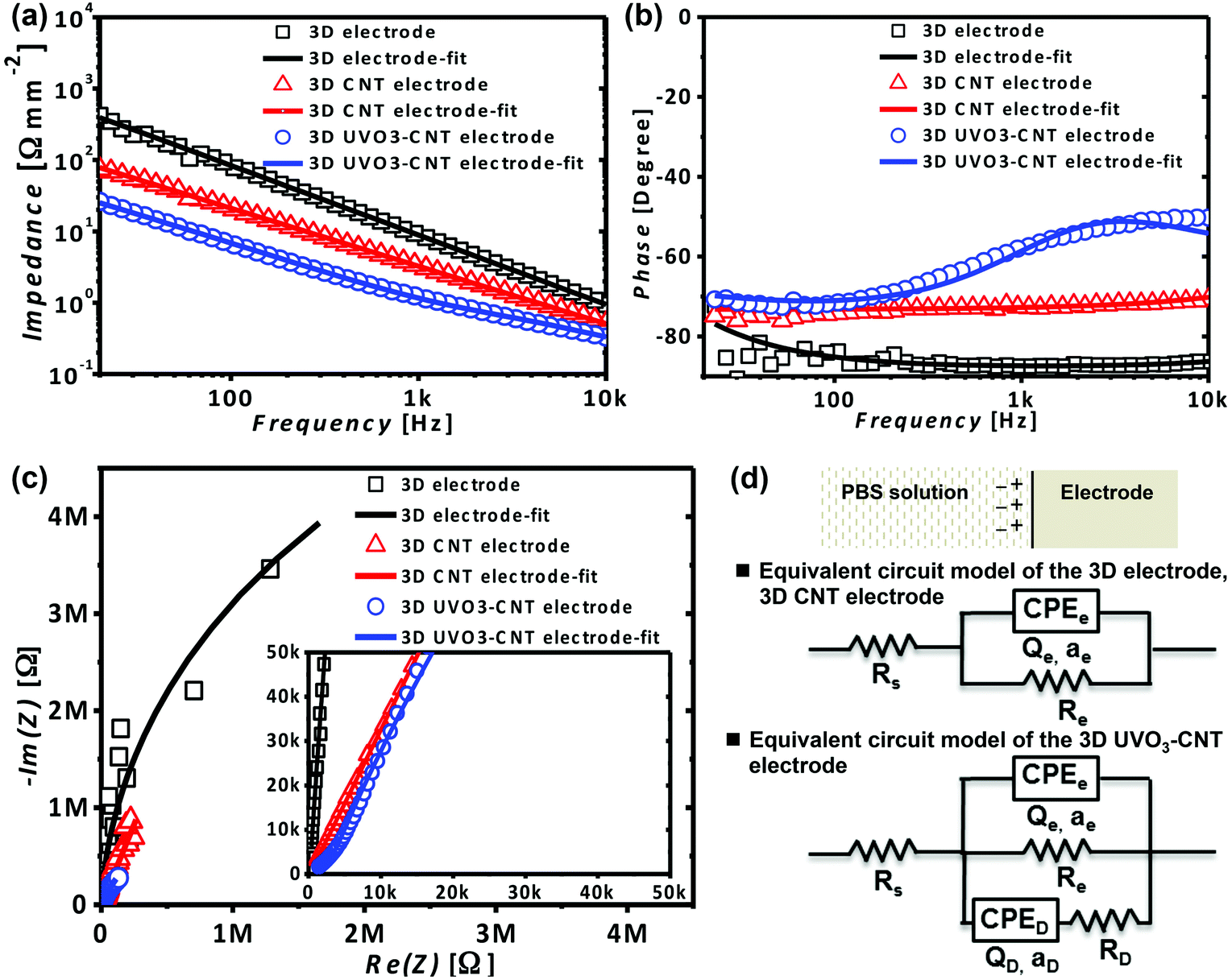 | ||
| Fig. 2 (a) The impedance and (b) phase versus frequency of 3D electrodes, 3D CNT electrodes and 3D UVO3-CNT electrodes in the range of 20 Hz–10 kHz. (c) The Nyquist plots of 3D electrodes, 3D CNT electrodes and 3D UVO3-CNT electrodes and (d) their data-fitted equivalent circuit models. | ||
To further study the influences of CNTs and UV/O3 treatment on the interface, the results of EIS measurements were fitted into equivalent circuit models of interfacial electrochemistry by EC-lab. The EIS data of 3D electrodes and 3D CNT electrodes could be fitted into a typical model for the electrode/electrolyte interface, known as the Randles circuit.19,20 It was represented by a solution resistance (Rs) in series with interfacial components which included a constant phase element (CPEe) and a faradic resistance (Re) in parallel. However, in the case of 3D UVO3-CNT electrodes, additional defect elements, a CPED in series with a RD, also existed in the interfacial components, which were in parallel with the CPEe and Re as the equivalent circuit models presented in Fig. 2d. The defect elements suggested that some CNTs were damaged after UV/O3 treatment, leading to the consequence of defect resistance RD other than the capacitive contribution from CNTs. The parameter fitted results are shown in Table A.1.† The fitted interfacial capacitance Qe normalized with the surface area increased from 2.2 mF cm−2 (3D electrodes) to 25.1 mF cm−2 (3D CNT electrodes). The capacitance was elevated by an order, which suggested that CNTs enhance capacitive coupling and therefore lower the impedance. The Qe was further improved by UV/O3 treatment to 73.3 mF cm−2 (3D UVO3-CNT electrodes), which was about 3 times larger than that of 3D CNT electrodes. The result implied that UV/O3 hydrophilic treatment made the surface electrolyte-accessible 3 times more than that of as-grown CNT electrodes and thus the impedance decreased to 1/3 compared to that of 3D CNT electrodes. The EIS data along with the fitted results suggested that the improvement of interfacial capacitance, resulting from CNT growth and a larger interfacial area, contributed to the intense decrease of interfacial impedance.
Electrophysiological recording of the 3D CNT electrodes
In order to characterize the capability of the 3D UVO3-CNT electrodes for electrophysiological signal detection, they were employed to record the signals of the zebrafish heart and the hippocampal neuron. The actual photograph and schematics of the cardiac recording system for zebrafish are shown in Fig. 3a and b. The zebrafish heart was pressed on 3D UVO3-CNT electrodes for better contact and the recorded ECG signals are demonstrated in Fig. 3c. On the other hand, stainless steel needle electrodes were used as a control for comparison (Fig. 3d). The recorded ECG signals from 3D UVO3-CNT electrodes showed regular and distinct P waves, QRS complexes, and T waves, which indicated the feasibility of 3D UVO3-CNT electrodes to monitor the depolarization and repolarization of atriums and ventricles. From the zoom-in image of Fig. 3c, the average peak-to-peak voltage (Vp–p) of the QRS complexes was 470.6 μV and the root-mean-square of the noise voltage (Vrms) was 2.8 μV. Therefore the SNR of the recorded ECG data was 168. Compared to the needle electrodes with a lower SNR of 120, 3D UVO3-CNT electrodes illustrated the better capability of monitoring the ECG of zebrafish hearts for applications in cardiovascular development and disease as well as drug testing. The amplitude of the T wave recorded was 150.2 μV with a narrow shape by 3D UVO3-CNT electrodes, but 128.5 μV with a wide waveform by stainless steel needle electrodes. The T wave could be recognized more easily with the higher and sharper shape using 3D UVO3-CNT electrodes, resulting from their good electrical properties and the small electrode size for better signal resolution.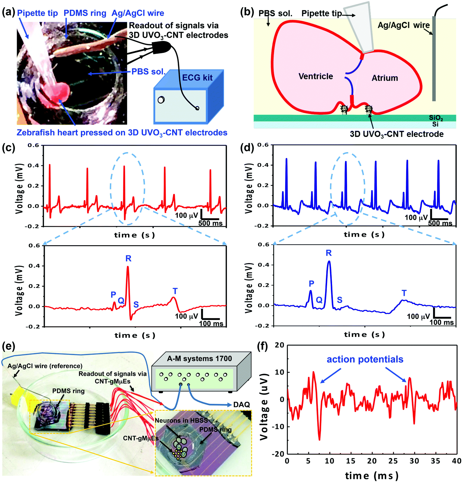 | ||
| Fig. 3 The ECG recording of zebrafish and the neural recording of rat hippocampus. (a) The actual photograph and schematic of the cardiac recording system for zebrafish. (b) The schematic of the boxed area in (a). The ECG tracing of zebrafish and the zoom-in tracing from the dashed area recorded from (c) 3D UVO3-CNT electrodes and (d) stainless steel needle electrodes. (e) The schematic and actual photograph of the neural recording system for rat hippocampus. (f) The extracellular recording of hippocampal action potentials. | ||
The recording of a single hippocampal neuron was demonstrated via the neuronal recording system as shown in Fig. 3e. Primary hippocampal neuronal cells were cultured on the 3D UVO3-CNT electrode chip. Since the size of the cell was larger than that of the 3D UVO3-CNT electrodes, the protruding electrodes would be engulfed and tightly sealed, leading to high detection resolution. The recording result is shown in Fig. 3f, which indicated that the 3D UVO3-CNT electrodes were capable of detecting the action potentials of hippocampal neurons. The Vp–p of action potential was 25.0 μV and the Vrms was 2.3 μV, providing a SNR of 11. The condition of the hippocampal cell culture could be further optimized to improve cell adhesion and increase the amplitude of Vp–p. Moreover, from the biocompatibility test (Fig. A.2†), neural cells and neurite outgrowth branches were observed on 3D UVO3-CNT electrode chips. The density of neuron cells on 3D UVO3-CNT electrode chips (80 ± 4 # mm−2) was not much inferior to that on the control glass sample (94 ± 10 # mm−2). The results indicated that 3D UVO3-CNT electrode chips were non-toxic to cells and exhibited good biocompatibility for long-term biomedical applications.
A comparison of some CNT-based microelectrodes is discussed as follows. There are other approaches to develop 3D structural electrodes with CNT interfaces for electrophysiological recording. For example, the cone-shaped 3D CNT probe of Su et al.,6 the CNT-coated sharp electrode of Keefer et al.,15 and the vertically aligned carbon nanofiber electrode of Yu et al.21 In this work, the 3D structure of the microelectrode is pin-shaped, which is different from the work mentioned above. The 3D structure is made of Au rather than Si in the work of Su et al.6 The conductivity of Au is much better than doped Si, therefore leading to a lower impedance. Moreover, direct growth of CNTs on the 3D electrode leads to better adhesion and no toxic elements compared to the electrochemical deposition of the CNT/KAuCN solution in the work of Keefer et al.15 On the other hand, unlike the work of Yu et al.21 where only the tip of CNFs was exposed as an electrode, the CNTs in this work could cover the whole surface of the pin-shaped structure using plated Ni as the catalyst. Therefore, CNTs provide not only better capacitance but also a larger surface area to obtain better electrical properties and electrophysiological performance.
According to the electrophysiological results, 3D UVO3-CNT electrodes provided better performance than stainless steel needle electrodes for zebrafish ECG recording. The small size of 3D UVO3-CNT electrodes gives higher levels of spatial resolution, providing a promising way to study ECG signals comprehensively, especially for zebrafish larvae. The high SNR and distinct T wave make 3D UVO3-CNT electrodes suitable for the detection of long QT syndromes. Applied to drug testing and screening, 3D UVO3-CNT electrodes exhibit potential to investigate QT-prolonging drugs.22 Moreover, it could also be designed and integrated with future wearable implantation for ECG monitoring.23
Conclusion
The feasibility of using 3D UVO3-CNT electrodes for the detection of electrophysiological signals was demonstrated. CNTs were successfully synthesized on the surface of a pin-shaped microstructure by CVD at a low temperature (400 °C), which was compatible with IC processes. From the EIS analyses, the impedance of 3D electrodes after CNT growth and UV/O3 treatment was lowered from 9.3 Ω mm−2 to 1.2 Ω mm−2 and the capacitance was elevated from 2.2 mF cm−2 to 73.3 mF cm−2. Attributed to the existence of UVO3-treated CNTs, the interfacial capacitance was improved largely, leading to the decrease of impedance. According to the results of electrophysiological recording on zebrafish hearts, 3D UVO3-CNT electrodes were demonstrated to have the capability of identifying the distinct ECG waves. The high levels of SNR and T wave resolution were suitable for detecting long QT syndromes and investigating QT-prolonging drugs. The small electrode size provided a future chance to study zebrafish larvae and to design wearable implantation. The 3D UVO3-CNT electrodes were also capable of detecting action potentials of rat hippocampus neurons. It was also shown that the 3D UVO3-CNT electrode chip was non-toxic from the biocompatibility test and therefore suitable for long-term performance. This research shows that the 3D UVO3-CNT electrode exhibits a potential candidate for applications in electrophysiological research and clinic trials.Acknowledgements
This work was supported by the National Science Council of Republic of China (Taiwan) under project numbers NSC 101-2627-E-007-001 and NSC 100-2221-E-007-022-MY3. The authors would like to thank the cMEA team and Dr Pin Chang for very valuable discussions and facility support at NTHU.Notes and references
- N. A. Kotov, J. O. Winter, I. P. Clements, E. Jan, B. P. Timko, S. Campidelli, S. Pathak, A. Mazzatenta, C. M. Lieber and M. Prato, Adv. Mater., 2009, 21, 3970–4004 CrossRef CAS.
- X. Duan, T.-M. Fu, J. Liu and C. M. Lieber, Nano Today, 2013, 8, 351–373 CrossRef CAS PubMed.
- M. E. Spira and A. Hai, Nat. Nano, 2013, 8, 83–94 CrossRef CAS PubMed.
- K. Ju-Hyun, K. Gyumin, N. Yoonkey and C. Yang-Kyu, Nanotechnology, 2010, 21, 085303 CrossRef PubMed.
- D. Brüggemann, B. Wolfrum, V. Maybeck, Y. Mourzina, M. Jansen and A. Offenhäusser, Nanotechnology, 2011, 22, 265104 CrossRef PubMed.
- H.-C. Su, C.-M. Lin, S.-J. Yen, Y.-C. Chen, C.-H. Chen, S.-R. Yeh, W. Fang, H. Chen, D.-J. Yao and Y.-C. Chang, Biosens. Bioelectron., 2010, 26, 220–227 CrossRef CAS PubMed.
- A. Hai, J. Shappir and M. E. Spira, Nat. Methods, 2010, 7, 200–202 CrossRef CAS PubMed.
- A. Hai, J. Shappir and M. E. Spira, J. Neurophysiol., 2010, 104, 559–568 CrossRef CAS PubMed.
- S. Iijima, Nature, 1991, 354, 56–58 CrossRef CAS.
- J. Li, H. T. Ng, A. Cassell, W. Fan, H. Chen, Q. Ye, J. Koehne, J. Han and M. Meyyappan, Nano Lett., 2003, 3, 597–602 CrossRef CAS.
- S.-R. Yeh, Y.-C. Chen, H.-C. Su, T.-R. Yew, H.-H. Kao, Y.-T. Lee, T.-A. Liu, H. Chen, Y.-C. Chang, P. Chang and H. Chen, Langmuir, 2009, 25, 7718–7724 CrossRef CAS PubMed.
- V. Lovat, D. Pantarotto, L. Lagostena, B. Cacciari, M. Grandolfo, M. Righi, G. Spalluto, M. Prato and L. Ballerini, Nano Lett., 2005, 5, 1107–1110 CrossRef CAS PubMed.
- M. Musameh, N. S. Lawrence and J. Wang, Electrochem. Commun., 2005, 7, 14–18 CrossRef CAS.
- K. Wang, H. A. Fishman, H. Dai and J. S. Harris, Nano Lett., 2006, 6, 2043–2048 CrossRef CAS PubMed.
- E. W. Keefer, B. R. Botterman, M. I. Romero, A. F. Rossi and G. W. Gross, Nat. Nano, 2008, 3, 434–439 CrossRef CAS PubMed.
- H. L. Hsu, I. J. Teng, Y. C. Chen, W. L. Hsu, Y. T. Lee, S. J. Yen, H. C. Su, S. R. Yeh, H. Chen and T. R. Yew, Adv. Mater., 2010, 22, 2177–2181 CrossRef CAS PubMed.
- W.-Y. Cheng, W.-L. Hsu, H.-H. Cheng, Z.-H. Huang and Y.-C. Chang, Anal. Biochem., 2009, 386, 105–112 CrossRef CAS PubMed.
- M. S. Dresselhaus, G. Dresselhaus, R. Saito and A. Jorio, Phys. Rep., 2005, 409, 47–99 CrossRef.
- B. Ershler, Discuss. Faraday Soc., 1947, 1, 269–277 RSC.
- J. Randles, Discuss. Faraday Soc., 1947, 1, 11–19 RSC.
- Z. Yu, T. E. McKnight, M. N. Ericson, A. V. Melechko, M. L. Simpson and B. Morrison, Nano Lett., 2007, 7, 2188–2195 CrossRef CAS PubMed.
- S. S. Dhillon, É. Dóró, I. Magyary, S. Egginton, A. Sík and F. Müller, PLoS One, 2013, 8, e60552 CAS.
- X. Zhang, T. Beebe, N. Jen, C. A. Lee, Y. Tai and T. K. Hsiai, Biosens. Bioelectron., 2015, 71, 150–157 CrossRef CAS PubMed.
Footnote |
| † Electronic supplementary information (ESI) available. See DOI: 10.1039/c5an01750e |
| This journal is © The Royal Society of Chemistry 2016 |