Photoreduction of CO2 to CO by a mononuclear Re(I) complex and DFT evaluation of the photocatalytic mechanism
Jamaladin Shakeriab,
Hossein Farrokhpour*a,
Hassan Hadadzadeh*a and
Mohammad Joshaghanib
aDepartment of Chemistry, Isfahan University of Technology, Isfahan 84156-83111, Iran. E-mail: h-farrokh@cc.iut.ac.ir; hadad@cc.iut.ac.ir; Fax: +98 3133912350; Tel: +98 3133913240
bFaculty of Chemistry, Razi University, Kermanshah, 67149, Iran
First published on 30th April 2015
Abstract
A new method was reported for the high-yield synthesis of a mononuclear Re(I) complex, fac-[Re(phen-dione)(CO)3Cl] (where phen-dione = 1,10-phenanthroline-5,6-dione). The photochemical activity of the Re(I) complex for the photoreduction of CO2 to CO was investigated under different conditions. Density functional theory (DFT) calculations were used to evaluate the photocatalytic mechanism for the photoreduction of CO2 to CO in the presence of the Re(I) complex as a photocatalyst through a detailed comparison of two potential pathways: (I) regeneration of the initial catalyst, and (II) formation of a solvent-coordinated Re(I) complex. Although the theoretical calculations reveal that the regeneration of the initial photocatalyst through the reassociation of the Re(I) cationic intermediate with Cl− is more thermodynamically favorable than the formation of a solvent-coordinated Re(I) species, the present results show that both catalytic cycles with the inclusion of solvation effects are thermodynamically favorable.
1. Introduction
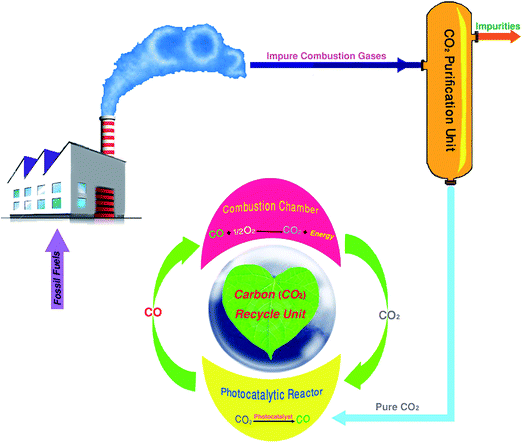
CO2 is one of several polyatomic molecules that are implicated in the greenhouse effect. Its increase in the atmosphere is considered to be a major contributor to global warming and the climate changes that come as a direct consequence.1 Carbon has three main oxides, CO, CO2, and C3O2 (carbon suboxide or tricarbon dioxide). CO2 is the most thermodynamically stable oxide of carbon at room temperature which requires a lot of energy to convert into other chemicals.2 In recent years, the chemical conversion of CO2 into useful chemicals such as CO (as a fuel: CO + 1/2O2 → CO2 + energy) is an interesting solution to the world's demand for fuels, decrease of greenhouse gas emissions, and recycling of carbon (Scheme 1).3 Particularly, the use of mononuclear tricarbonyl polypyridyl rhenium(I) complexes such as [Re(diimine)(CO)3X] (X = Cl−, Br−, CN−, and SCN−; and diimine = bpy, phen, phen-dione, and dppz) for reduction of CO2 have attracted a lot of attention due to their ability to absorb light, store redox equivalents, and convert CO2 into higher-energy products.4–10 These complexes, with various X, exhibit different catalytic activities while keeping aromatic diimine ligands constant. For example, in fac-[Re(bpy)(CO)3X] (X = SCN−, Cl−, and CN−) complexes, it has been identified that the photocatalytic activities of these three complexes for reduction of CO2 to CO are very different. In the case of X = SCN−, 60 μmol of CO gas was produced after 25 h of irradiation, which was two times higher than the value found in X = Cl− under the same condition; although, X = CN− cannot act as a photocatalyst.7 Also, rhenium complexes with different aromatic diimine ligands and appropriate X ligand have been the subject of several studies.8 For example, Kubiak and co-workers9,10 have reported the improved electrocatalytic activity by altering the substituent at the 4- and 4′-positions of the bipyridine (bpy) ligand. The complex with 4,4′-tBu2bpy exhibits a catalytic activity for reduction of CO2 which is about four times greater than that is observed with a simple bipyridine complex (Scheme 2).One interesting feature of CO2 reduction by Re complexes is investigation of the photocatalytic and electrocatalytic mechanisms involved in this reduction.11 In particular, the mechanism of the photochemical reduction of CO2 by rhenium complexes has been largely studied so far. In general, due to the presence of different species in solution, an exact determination of the photocatalytic mechanism in solution is often difficult. Some of these species are as follows: triethylamine (TEA) or triethanolamine (TEOA) as the sacrificial electron donor, the solvent that has ability to coordinate to metal ions (dimethylformamide (DMF), dimethyl sulfoxide (DMSO), or CH3CN), the subsequent byproducts, different intermediates, and sometimes NR4Cl (R = Et or Bu) as a chloride source. Upon irradiation, the Re(I) complex is promoted to an MLCT excited state with a Re(II) metal center and an electron located on the empty π* orbital of polypyridyl ligands. Sacrificial electron donors are added in excess to quench the excited state and prevent the back-electron transfer. In this step, a one-electron-reduced (OER) intermediate is formed, which is an initiator for photocatalytic reaction. After the dissociation of chloride anion, a solvent-coordinated Re(I) complex is formed. The CO2-coordinated rhenium complex is one of the most important intermediates in the photocatalytic reduction of CO2 to CO, which has been previously investigated for [Re(dmbpy)(CO)3Cl].12 For the first time, a CO2-coordinated rhenium bipyridyl complex, [Re(dmbpy)(CO)3(COOH)], has been successfully detected by cold-spray ionization mass spectrometry (CSI-MS).12 On the basis of previous experimentally studies, the photocatalytic mechanism for the reduction of CO2 to CO in the presence of the Re(I) complex as a photocatalyst has been also investigated through a detailed comparison of two potential pathways: (I) regeneration of the initial catalyst through the reassociation of the Re(I) cationic intermediate with Cl−, investigated by Ishitani and co-workers;7 and (II) formation of a solvent-coordinated Re(I) complex without the replacement of Cl−, proposed by Inoue's group.12 Although, much research has been done on the mechanism of the photochemical reduction of CO2 by rhenium complexes, but there are still some questions left unanswered about the intermediates and the reaction pathways.
In this study, a new method for the preparation of a mononuclear Re(I) phen-dione complex, fac-[Re(phen-dione)(CO)3Cl], and its photocatalytic activity for reduction of CO2 to CO have been reported. In addition, the theoretical calculations, at the density functional theory (DFT), were used to evaluate the photocatalytic mechanism for the photoreduction of CO2 to CO. The free energy profiles of the considered mechanisms were also obtained and discussed. Two mechanisms have been proposed for the photocatalytic reduction of CO2 to CO using this mononuclear Re(I) complex.
2. Experimental
2.1. Materials and measurements
All chemicals and solvents were commercially available in high purity and used without further purification. Re2(CO)10 (dirhenium decacarbonyl) was purchased from Merck. 1,10-Phenanthroline-5,6-dione (phen-dione), 2-chloroethanol, triethylamine (TEA), triethanolamine (TEOA), DMF, and NEt4Cl were obtained from Aldrich.Elemental analyses were carried out on a Leco, CHNS-932 instrument. FT-IR spectra were recorded on an FT-IR JASCO 680-PLUS spectrometer. 1H and 13C-{1H} NMR spectra were recorded on a Bruker Avance III-400 NMR spectrometer at 298 K. The UV-vis spectra were recorded on a JASCO-570 spectrophotometer. Fluorescence spectra were recorded with a JASCO FP-750 spectrofluorometer at room temperature in DMF. Gas chromatograms were recorded with a Varian STAR 3400 gas chromatograph with He as the carrier gas.
All photocatalytic reactions were performed in a quartz test tube (i.d. = 12 mm; 18 mL volume) containing 10 mL DMF/TEA (4![[thin space (1/6-em)]](https://www.rsc.org/images/entities/char_2009.gif) :
:![[thin space (1/6-em)]](https://www.rsc.org/images/entities/char_2009.gif) 1 v/v), DMF/TEOA (4
1 v/v), DMF/TEOA (4![[thin space (1/6-em)]](https://www.rsc.org/images/entities/char_2009.gif) :
:![[thin space (1/6-em)]](https://www.rsc.org/images/entities/char_2009.gif) 1 v/v), or DMF/TEOA/NEt4Cl (4
1 v/v), or DMF/TEOA/NEt4Cl (4![[thin space (1/6-em)]](https://www.rsc.org/images/entities/char_2009.gif) :
:![[thin space (1/6-em)]](https://www.rsc.org/images/entities/char_2009.gif) 1 v/v, containing 10 mg NEt4Cl) solution of the Re(I) complex (2 × 10⁻⁴ M) after bubbling through with pure CO2 for 20 min at room temperature. The CO2 concentration in solutions is about 0.2 M at 0.1 MPa and 25 °C. Each sample solution was irradiated by a high-pressure mercury lamp with a 365 nm band-pass filter for 0–24 h with stirring. The temperature of the reaction solution was maintained at 25 ± 2 °C by a fan cooling system during the irradiation process. The intensity of the mercury lamp was determined using a standard actinometer K3[Fe(C2O4)3]. After each irradiation step, a gas sample was taken using a gas-tight syringe and the produced CO gas was detected by gas chromatograph (GC). In all experiments, only CO gas with no detectable quantity of H2 gas was found in the headspace of the reaction vessels. The irradiation of the tricarbonyl Re(I) complex with UV rays of 365 nm may lead to photodissociation and photodecomposition reactions. In addition, the irradiation of one fac-[Re(phen-dione)(CO)3Cl] molecule may release three CO molecules in the absence of CO2 atmosphere ([Re(phen-dione)(CO)3Cl] → [Re(phen-dione)(solvent)3Cl] + 3CO). To confirm the stability of [Re(phen-dione)(CO)3Cl] in the DMF/TEA, DMF/TEOA, and DMF/TEOA/NEt4Cl solutions at room temperature, a UV-vis study was performed under conditions similar to those used for the photocatalytic reactions in the absence of CO2 atmosphere. The spectral features of fac-[Re(phen-dione)(CO)3Cl] exhibited no change in the position of absorption bands over a period of 24 h under irradiation of the UV lamp (365 nm), and no precipitation or turbidity was observed even after long storage at room temperature (at least 4 weeks after preparation). Also, no detectable quantity of CO gas was found in the headspace of the blank solutions (the solutions of [Re(phen-dione)(CO)3Cl] in the DMF/TEA, DMF/TEOA, or DMF/TEOA/NEt4Cl mixture without CO2 added) after irradiation at 365 nm for 24 h. This suggests that the Re(I) complex is completely stable under the experimental conditions.
1 v/v, containing 10 mg NEt4Cl) solution of the Re(I) complex (2 × 10⁻⁴ M) after bubbling through with pure CO2 for 20 min at room temperature. The CO2 concentration in solutions is about 0.2 M at 0.1 MPa and 25 °C. Each sample solution was irradiated by a high-pressure mercury lamp with a 365 nm band-pass filter for 0–24 h with stirring. The temperature of the reaction solution was maintained at 25 ± 2 °C by a fan cooling system during the irradiation process. The intensity of the mercury lamp was determined using a standard actinometer K3[Fe(C2O4)3]. After each irradiation step, a gas sample was taken using a gas-tight syringe and the produced CO gas was detected by gas chromatograph (GC). In all experiments, only CO gas with no detectable quantity of H2 gas was found in the headspace of the reaction vessels. The irradiation of the tricarbonyl Re(I) complex with UV rays of 365 nm may lead to photodissociation and photodecomposition reactions. In addition, the irradiation of one fac-[Re(phen-dione)(CO)3Cl] molecule may release three CO molecules in the absence of CO2 atmosphere ([Re(phen-dione)(CO)3Cl] → [Re(phen-dione)(solvent)3Cl] + 3CO). To confirm the stability of [Re(phen-dione)(CO)3Cl] in the DMF/TEA, DMF/TEOA, and DMF/TEOA/NEt4Cl solutions at room temperature, a UV-vis study was performed under conditions similar to those used for the photocatalytic reactions in the absence of CO2 atmosphere. The spectral features of fac-[Re(phen-dione)(CO)3Cl] exhibited no change in the position of absorption bands over a period of 24 h under irradiation of the UV lamp (365 nm), and no precipitation or turbidity was observed even after long storage at room temperature (at least 4 weeks after preparation). Also, no detectable quantity of CO gas was found in the headspace of the blank solutions (the solutions of [Re(phen-dione)(CO)3Cl] in the DMF/TEA, DMF/TEOA, or DMF/TEOA/NEt4Cl mixture without CO2 added) after irradiation at 365 nm for 24 h. This suggests that the Re(I) complex is completely stable under the experimental conditions.
2.2. Synthesis of fac-[Re(phen-dione)(CO)3Cl]
Although, the synthesis of fac-[Re(phen-dione)(CO)3Cl] has previously reported,13 here this complex was prepared according to a new method with a high yield (78%). In a typical experiment, a mixture of 210 mg (0.322 mmol) of Re2(CO)10 and 162 mg (0.766 mmol) of phen-dione was refluxed in 35 mL of 2-chloroethanol for 12 h under N2 atmosphere, during which time the color of the reaction mixture changed from pale yellow to orange. After being cooled to room temperature, the solution was filtered and evaporated to dryness to give an orange residue. The purification of the crude product was carried out by column chromatography (Al2O3, grade III, WA, 30 × 1 cm column). Elution with chloroform/toluene (1![[thin space (1/6-em)]](https://www.rsc.org/images/entities/char_2009.gif) :
:![[thin space (1/6-em)]](https://www.rsc.org/images/entities/char_2009.gif) 1 v/v) gave a yellow band of the pure complex, which was collected, evaporated to dryness, and then recrystallized by slow evaporation of a CH2Cl2–hexane (1
1 v/v) gave a yellow band of the pure complex, which was collected, evaporated to dryness, and then recrystallized by slow evaporation of a CH2Cl2–hexane (1![[thin space (1/6-em)]](https://www.rsc.org/images/entities/char_2009.gif) :
:![[thin space (1/6-em)]](https://www.rsc.org/images/entities/char_2009.gif) 1 v/v) solution of the complex at 5 °C. The microcrystals of the Re(I) complex were collected by filtration. Yield: 260 mg (78%). Elemental anal. calcd for C15H6ClN2O5Re: C, 34.98; H, 1.18; N, 5.41. Found: C, 35.14; H, 1.17; N, 5.38%. IR (KBr; νmax/cm−1): CO = 2100 (s), 1920, 1850 (s); phen-dione = 1700 (m), 1680 (w), 1570 (m), 1457 (w), 1412 (w), 1111 (w), 810 (w), 737 (w). UV-vis (DMF; λ/max, nm (ε, M−1 cm−1): 270 (9860), 308 (5789), and 365 (2500). 1H NMR (δ (ppm), DMSO-d6): 9.03 (dd, 2H), 8.58 (dd, 2H), 8.05 (dd, 2H). 13C-{1H} NMR (δ (ppm), DMSO-d6): 188.5–197 (s, Ccarbonyl), 173 (s, C
1 v/v) solution of the complex at 5 °C. The microcrystals of the Re(I) complex were collected by filtration. Yield: 260 mg (78%). Elemental anal. calcd for C15H6ClN2O5Re: C, 34.98; H, 1.18; N, 5.41. Found: C, 35.14; H, 1.17; N, 5.38%. IR (KBr; νmax/cm−1): CO = 2100 (s), 1920, 1850 (s); phen-dione = 1700 (m), 1680 (w), 1570 (m), 1457 (w), 1412 (w), 1111 (w), 810 (w), 737 (w). UV-vis (DMF; λ/max, nm (ε, M−1 cm−1): 270 (9860), 308 (5789), and 365 (2500). 1H NMR (δ (ppm), DMSO-d6): 9.03 (dd, 2H), 8.58 (dd, 2H), 8.05 (dd, 2H). 13C-{1H} NMR (δ (ppm), DMSO-d6): 188.5–197 (s, Ccarbonyl), 173 (s, C![[double bond, length as m-dash]](https://www.rsc.org/images/entities/char_e001.gif) Ophen-dione) 136.3–165 (s, Cpyridyl).
Ophen-dione) 136.3–165 (s, Cpyridyl).
2.3. Computational details
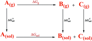
All calculations were carried out using the GAUSSIAN 09 suite of programs14 and Mopac 2007 software. The geometrical structures of the considered complexes involved in the photocatalytic cycles were fully optimized without any symmetry restrictions in both gas and solution phases using the PM7 semi-empirical method implemented in Mopac 2007 software. The COSMO method was used for modeling the solvent in optimizing the structures in DMF. The calculated optimized structures in the gas and solution phases were used for frequency calculation at the DFT method using M062X functional.15 6-31+G(d) basis set for C, H, N and Cl; and the effective core potential, LANL2DZ, for Re were used for the frequency calculations. The SMD model16 was used for modeling the solvent in the frequency calculation. To calculate the free energy solvation of the structures involved in the photocatalytic cycles in DMF, a thermodynamic cycle presented in Scheme 6 was used. Also, the dipole moment, energies of the frontier molecular orbitals (FMOs), and atomic charges were determined at the same level of theory.3. Results and discussion
3.1. Synthesis
The synthesis strategy for the Re(I) complex is summarized in Scheme 3. The complex was synthesized by reacting Re2(CO)10 with 1,10-phenanthroline-5,6-dione (phen-dione) in dry 2-chloroethanol under a nitrogen atmosphere. The complex was purified by column chromatography.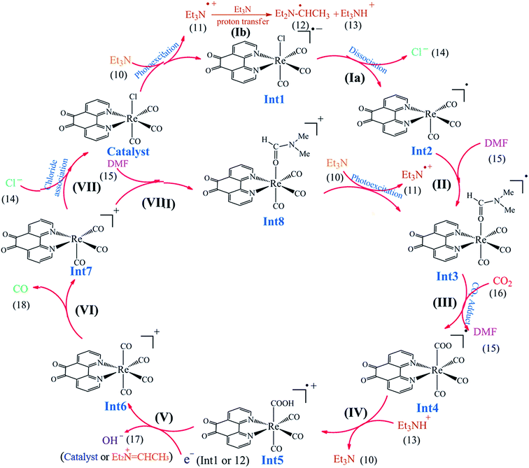 | ||
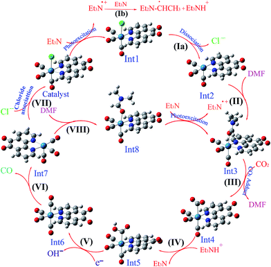
| Scheme 3 The proposed reaction mechanism for the photocatalytic reduction of CO2 to CO by the Re(I) complex. | ||
No investigation was performed on the mechanism of the synthesis of [Re(phen-dione)(CO)3Cl]. Although the synthesis of fac-[Re(phen-dione)(CO)3Cl] has been previously reported,13 the reaction yield was low. In addition, our synthesis method is totally different and has a higher reaction yield and a shorter reaction time. In the previous method, the Re precursor is Re(CO)5Cl, but in this paper, Re2(CO)10 is the starting complex and the origin of the chloro ligand is solvent 2-chloroethanol (ClCH2CH2OH). The following reaction can be proposed to account for the formation of the Re–Cl bond in 2-chloroethanol (eqn (1)).17
| Re2CO10 + 2(diimine) + 2Cl-CH2CH3OH → 2fac-[Re(diimine)(CO)3Cl] + CH3CH2OH + 4CO + ClCH2CHO | (1) |
3.2. Photophysical properties
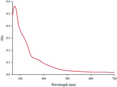
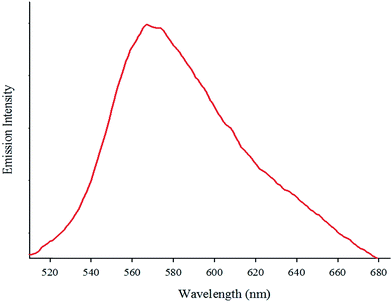
The absorption spectrum of the complex in DMF (5.7 × 10⁻⁵ M) at room temperature is depicted in Fig. 1. The complex shows two intense absorption bands at 270 (ε = 9860 M−1 cm−1) and 308 nm (ε = 5789 M−1 cm−1) that can be assigned to the spin-allowed intraligand (π → π*) transitions. By contrast, the broad band at 365 nm (ε = 2500 M−1 cm−1) is attributed to the dπ(Re(I)) → π*(phen-dione), metal-to-ligand charge-transfer (MLCT) transition.18,19 The emission spectrum of the complex at room temperature is shown in Fig. 2. When the complex was excited at 365 nm, a broad emission band was appeared at 570 nm.The IR spectrum of the complex contains three strong ν(CO) absorption bands at 2100, 1920, and 1850 cm−1 which confirms a facial geometry (fac) for three CO ligands in the complex. Generally, a facial isomer has three intense bands in the carbonyl region, although the meridional isomer (mer) has only two intense bands.20 The bands around 1700–1400 cm−1 are assigned to the stretching of the phen-dione rings.
3.3. NMR studies
The rhenium(I) complex was characterized using 1H and 13C NMR techniques in DMSO-d6. The aromatic region of the 1H NMR spectrum is integrated for 6 protons, as expected for coordinated pyridyl rings, including three different pairs of protons. The 13C NMR shows the difference between Ccarbonyl, Cpyridyl, and C![[double bond, length as m-dash]](https://www.rsc.org/images/entities/char_e001.gif) Ophen-dione very well. The 1H and 13C NMR data of the complex are given in the Experimental section.
Ophen-dione very well. The 1H and 13C NMR data of the complex are given in the Experimental section.
3.4. Photocatalytic reduction of CO2 to CO
The photocatalytic experiments were performed in three CO2-saturated solutions of the complex (2 × 10⁻⁴ M) in DMF/TEA (4![[thin space (1/6-em)]](https://www.rsc.org/images/entities/char_2009.gif) :
:![[thin space (1/6-em)]](https://www.rsc.org/images/entities/char_2009.gif) 1 v/v), DMF/TEOA (4
1 v/v), DMF/TEOA (4![[thin space (1/6-em)]](https://www.rsc.org/images/entities/char_2009.gif) :
:![[thin space (1/6-em)]](https://www.rsc.org/images/entities/char_2009.gif) 1 v/v), or DMF/TEOA/NEt4Cl (4
1 v/v), or DMF/TEOA/NEt4Cl (4![[thin space (1/6-em)]](https://www.rsc.org/images/entities/char_2009.gif) :
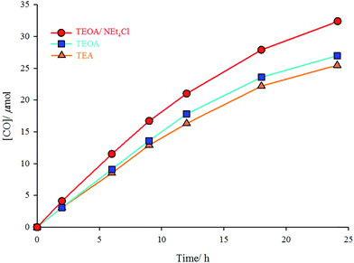
:![[thin space (1/6-em)]](https://www.rsc.org/images/entities/char_2009.gif) 1 v/v containing 10 mg NEt4Cl) mixture under UV radiation of 365 nm at room temperature. TEA and TEOA are sacrificial donors; and NEt4Cl is a free chloride source. In the solution of the complex in DMF/TEOA mixture, 27 μmol of CO was produced after 24 h of irradiation, whereas only 25.5 μmol of CO was formed in DMF/TEA mixture under the same conditions. Addition of an excess amount (10 mg) of NEt4Cl (as a chloride source) to the DMF/TEOA mixture increases the moles of produced CO to 34 μmol (Fig. 3). The turnover number for the formation of CO (TNCO: based on the complex concentration (TNCO = (mol of CO at 24 h)/(mol of the catalyst)) in this research is comparable with similar complexes.21 The turnover numbers for the formation of CO were 12.8, 13.5, and 17 using DMF/TEA, DMF/TEOA, and DMF/TEOA/NEt4Cl solutions, respectively.
1 v/v containing 10 mg NEt4Cl) mixture under UV radiation of 365 nm at room temperature. TEA and TEOA are sacrificial donors; and NEt4Cl is a free chloride source. In the solution of the complex in DMF/TEOA mixture, 27 μmol of CO was produced after 24 h of irradiation, whereas only 25.5 μmol of CO was formed in DMF/TEA mixture under the same conditions. Addition of an excess amount (10 mg) of NEt4Cl (as a chloride source) to the DMF/TEOA mixture increases the moles of produced CO to 34 μmol (Fig. 3). The turnover number for the formation of CO (TNCO: based on the complex concentration (TNCO = (mol of CO at 24 h)/(mol of the catalyst)) in this research is comparable with similar complexes.21 The turnover numbers for the formation of CO were 12.8, 13.5, and 17 using DMF/TEA, DMF/TEOA, and DMF/TEOA/NEt4Cl solutions, respectively.
3.5. Theoretical calculations
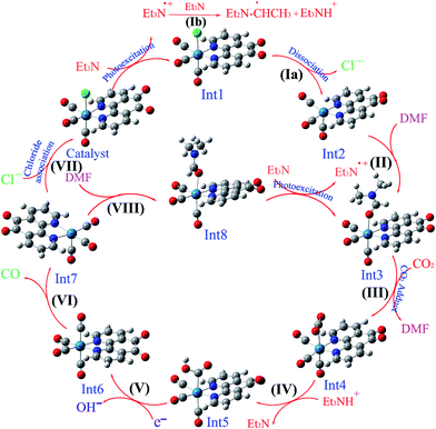 | ||
| Scheme 4 The optimized structures of the species involved in the proposed mechanisms in the gas phase. | ||
 | ||
| Scheme 5 The optimized structures of the species involved in the proposed mechanisms in the solution phase (DMF). | ||
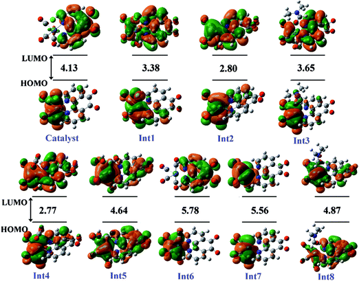 | ||
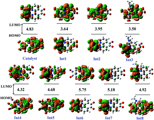
| Fig. 4 The distribution and energy (eV) of FMOs (frontier molecular orbitals) of the species in the gas phase involved in the proposed mechanism. | ||
| Label | Structure | Go(gas) | ΔGo(solvation) |
|---|---|---|---|
| Catalyst | fac-[Re(phen-dione)(CO)3Cl] | −1599.582465 | −33.14 |
| Int1 | [Re(phen-dione)(CO)3Cl]˙− | −1599.698190 | −51.26 |
| Int2 | [Re(phen-dione)(CO)3]˙ | −1139.353627 | −45.69 |
| Int3 | [Re(phen-dione)(CO)3(DMF)]˙ | −1387.719252 | −30.87 |
| Int4 | [Re(phen-dione)(CO)3(CO2)]˙ | −1327.855635 | −30.23 |
| Int5 | [Re(phen-dione)(CO)3(COOH)]˙+ | −1328.190883 | −69.36 |
| Int6 | [Re(phen-dione)(CO)4]+ | −1252.460332 | −64.39 |
| Int7 | [Re(phen-dione)(CO)3]+ | −1139.151815 | −84.72 |
| Int8 | [Re(phen-dione)(CO)3(DMF)]+ | −1387.486166 | −63.10 |
| 10 | Et3N | −292.087395 | −4.58 |
| 11 | Et3N˙+ | −291.807198 | −57.53 |
| 12 | CH3C˙HNEt2 | −291.447005 | −4.51 |
| 13 | Et3NH+ | −291.807198 | −59.71 |
| 14 | Cl− | −460.250162 | −64.90 |
| 15 | DMF | −248.326950 | −7.67 |
| 16 | CO2 | −188.524719 | −1.39 |
| 17 | OH− | −75.744333 | −78.61 |
| 18 | CO | −113.290939 | +2.90 |
| Step | ΔGog | ΔGosol |
|---|---|---|
| Ia | +59.24 | −0.09 |
| Ib | +1.14 | −0.97 |
| II | −24.27 | −1.76 |
| III | +38.52 | +32.87 |
| IV | +14.51 | +30.51 |
| V | −8.65 | −82.29 |
| VI | +11.03 | −6.40 |
| VII | −113.65 | +2.83 |
| VIII | −4.64 | +24.65 |
The gas-phase Gibbs free energy change (ΔGogas) is calculated using eqn (2) (A is a reactant, and B and C are products, for a supposed reaction which take places in the standard condition).
| ΔGogas = Gogas(B) + Gogas(C) − Gogas(A) | (2) |
According to the thermodynamic cycle shown in Scheme 6,22 the term ΔGg is the gas-phase free energy change of the reaction and the term ΔGsol is the desired free energy change in solution which is calculated using eqn (3).
| ΔGsol = ΔGgas − ΔGAsol + ΔGBsol + ΔGCsol | (3) |
Three other parts, ΔGAsol, ΔGBsol, and ΔGCsol are the free energy of solvation of the reactant (A) and the products (B and C), respectively.
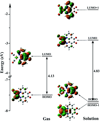 | ||
| Fig. 6 The energy levels and shapes of HOMO−1, HOMO, LUMO, and LUMO+1 orbitals of the Catalyst in the gas phase and solution. | ||
On the basis of previous study,12 after the electron transfer from Int1 or radical 12 (CH3C˙HNEt2) to [Re(phen-dione)(CO)3(COOH)]˙+ (Int5) and the dehydroxylation reaction in step V (Scheme 3), “the other O atom” of CO2 yields a hydroxide anion (OH−). Also, Gibson and co-workers4d afforded to study of photocatalytic reduction reaction of fac-[Re(dmbpy)(CO)3Cl] with CO2 which is generated fac-[Re(dmbpy)(CO)3COOH]. Their findings have shown that the Re–carboxylate complex converts to [Re(dmbpy)(CO)3]+ and OH−. The OH− and Et3NH+ ions undergo a neutralization reaction to generate H2O and Et3N.5d Also, the hydroxide anion can react with dissolved CO2 in DMF solution and produce a bicarbonate anion (OH− + CO2 → HCO3−). With inclusion of solvation, the step IV is predicted by our calculations (Table 2) to be nonspontaneous by +30.51 kcal mol−1, while the dehydroxylation reaction in step V is spontaneous by −82.29 kcal mol−1. Since the formation of a CO molecule from CO2 requires a 2-electron reduction of CO2, another electron in step VI should be necessary for the reduction of CO2, which is inputted into the 17–ē species generated by the loss of the chloro ligand from the OER species or the CO2 adduct.24 According to Ishitani et al.,7 the OER species (Int1) itself has strong reducing power (E1/2 = −1.61 V vs. Ag/AgNO3); or the radical reducing agent 12 (CH3C˙HNEt2) formed through step Ib,25 which are possibly the second electron sources. The dissociation of Int6 yields a CO molecule (18) and a rhenium cation Int7. This step is comparatively spontaneous by −6.40 kcal mol−1 in the solution phase. Previous papers have reported that the rhenium cation Int7 may then follow two potential pathways: one leading to regenerates Catalyst through a reassociation reaction of Int7 with a chloride anion (14) (step VII: +2.83 kcal mol−1, Scheme 3) and the other to transform into the DMF-coordinated rhenium cation Int8, without the replacement of Cl− (step VIII: +24.65 kcal mol−1, Scheme 3). The DMF-coordinated Re cation Int8 absorbs UV radiation to form the one-electron-reduced (OER) DMF-coordinated radical Int3, driving the continuous reaction cycle. The possibility of reaction progress through VII or VIII step has been debated in the literatures. In some cases, the increase of the lifetime of the OER Int1 (ref. 7) and CO formation by addition of an excess X− using [Re(diimine)(CO)3X]26 is one of the reasons for improvement of regeneration of the Catalyst through step VII. Also, Inoue et al.12 have studied the photochemical reduction of CO2 catalyzed by [Re(dmbpy)(CO)3Cl], they detected the DMF-coordinated Re complex ([Re(dmbpy)(CO)3(DMF)]) and CO2-coordinated Re complex ([Re(dmbpy)(CO)3(COOH)]). They proposed that a photochemical reduction of CO2 must occur through an intermediate similar to DMF-coordinated Re cation Int8 (step VIII). The DFT calculations reveal that the catalytic cycles in the gas phase and with inclusion of solvation through step VII has a significant driving force (−23.26 and −24.32 kcal mol−1 in the gas and solution phases, respectively), while the formation of the DMF-coordinated rhenium cation Int8 through step VIII is not very thermodynamically favorable (+80.33 and −0.66 kcal mol−1 in the gas and solution phases, respectively). The results also show that both possibility of reaction progress through step VII or VIII with inclusion of solvation are thermodynamically feasible, although the regeneration of Catalyst through step VII is much more suitable. The CSI-MS measurements of the reaction mixture and FT-IR studies12 have provided clear evidence for the formation of the DMF-coordinated Re cation similar to Int8 through step VIII. Finally, we can conclude that the catalytic cycle for CO2 reduction through step VIII is much more kinetically desirable.
4. Conclusions
We have reported here a new method for the preparation of a mononuclear Re(I) phen-dione complex, fac-[Re(phen-dione)(CO)3Cl] and its application as a photocatalyst for the photochemical reduction of CO2 to CO. According to the theoretical calculations, two catalytic pathways for the reduction of CO2 to CO were proposed. The proposed pathways are consistent with the experimental findings by Ishitani and Inoue. Actually, we have proposed the photocatalytic mechanism according to the formation of CO as the final product which was detected in the Experimental section. It's worthy to mention that, only CO gas with no detectable quantity of H2, formic acid, MeOH, or CH4 was found in the reaction mixture after irradiation. Also, the addition of an excess amount of NEt4Cl (as a chloride source) to the DMF/TEOA mixture increases the formation of CO. Since the reduction of CO2 to CO requires two electrons in step V in the proposed mechanism, another electron should be supplied by a strong reducing agent. According to Ishitani's studies, the OER species (Int1) acts as a reducing agent. Therefore, it can be confirmed the photoexcitation step and the dehydroxylation step (step V) occur in the solution. The formation of Int1 and radical 12 is increased when the excess chloride source NEt4Cl is added to the reaction mixture. As can be shown in Scheme 3, Int1 and radical 12 can act as a potential reducing agent. In addition, the polar solvent DMF (which was used in the Experimental section) is a suitable ligand for the formation of solvent-coordinated Re(I) in steps II and VIII (Scheme 3).The theoretical calculations were demonstrated both cycles for photochemical reduction of CO2 to CO in the presence of the Re(I) complex were thermodynamically possible. Although, the regeneration of the initial Catalyst, fac-[Re(phen-dione)(CO)3Cl], through a reassociation reaction with a chloro ligand is much more suitable. Also, the catalytic cycle for CO2 reduction through step VIII is much more kinetically desirable.
Acknowledgements
We are grateful to the Iran National Science Foundation (INSF) (Project no. 90006991) and Isfahan University of Technology (IUT) for financial support.References
- A. J. Morris, G. J. Meyer and E. Fujita, Acc. Chem. Res., 2009, 42, 1983–1994 CrossRef CAS PubMed.
- W. Leitner, Coord. Chem. Rev., 1996, 153, 257–284 CrossRef CAS.
- (a) K. Ikeue, H. Yamashita, M. Anpo and T. Takewaki, J. Phys. Chem. B, 2001, 105, 8350–8355 CrossRef CAS; (b) A. Khenkin, I. Efremenko, L. Weiner, J. Martin and R. Neumann, Chem.–Eur. J., 2010, 16, 1356–1364 CrossRef CAS PubMed; (c) C. Creutz, H. A. Schwarz, J. F. Wishart, E. Fujita and N. Sutin, J. Am. Chem. Soc., 1991, 113, 3361–3371 CrossRef CAS; (d) E. Simón-Manso and C. P. Kubiak, Organometallics, 2005, 24, 96–102 CrossRef; (e) H. Ishida, T. Terada, K. Tanaka and T. Tanaka, Organometallics, 1990, 6, 181–186 CrossRef.
- (a) B. Gholamkhass, H. Mametsuka, K. Koike, T. Tanabe, M. Furue and O. Ishitani, Inorg. Chem., 2005, 44, 2326–2336 CrossRef CAS PubMed; (b) J. Shakeri, H. Hadadzadeh and H. Tavakol, Polyhedron, 2014, 78, 112–122 CrossRef CAS PubMed; (c) C. Bruckmeier, M. W. Lehenmeier, R. Reithmeier, B. Rieger, J. Herranz and C. Kavakli, Dalton Trans., 2012, 41, 5026–5037 RSC; (d) D. H. Gibson, X. Yin, H. He and M. S. Mashuta, Organometallics, 2003, 22, 337–346 CrossRef CAS.
- (a) W. Kaim and S. Kohlmann, Chem. Phys. Lett., 1987, 139, 365–369 CrossRef CAS; (b) D. J. Stufkens, Inorg. Chem., 1992, 13, 359–369 CAS; (c) Y. Hayashi, S. Kita, B. S. Brunschwig and E. Fujita, J. Am. Chem. Soc., 2003, 125, 11976–11987 CrossRef CAS PubMed; (d) B. Kumar, M. Llorente, J. Froehlich, T. Dang, A. Sathrum and C. P. Kubiak, Annu. Rev. Phys. Chem., 2012, 63, 541–569 CrossRef CAS PubMed; (e) Y. Yan, E. L. Zeitler, J. Gu, Y. Hu and A. B. Bocarsly, J. Am. Chem. Soc., 2013, 135, 4020–14023 Search PubMed; (f) J. A. Keith, K. A. Grice, C. P. Kubiak and E. A. Carter, J. Am. Chem. Soc., 2013, 135, 15823–15829 CrossRef CAS PubMed; (g) C. Riplinger and E. A. Carter, ACS Catal., 2015, 5, 900–908 CrossRef CAS; (h) M. V. Vollmer, C. W. Machan, M. L. Clark, W. E. Antholine, J. Agarwal, H. F. Schaefer, C. P. Kubiak and J. R. Walensky, Organometallics, 2015, 34, 3–12 CrossRef CAS PubMed.
- J. Hawecker, J. M. Lehn and R. Ziessel, J. Chem. Soc., Chem. Commun., 1983, 536–538 RSC.
- H. Takeda, K. Koike, H. Inoue and O. Ishitani, J. Am. Chem. Soc., 2008, 130, 2023–2031 CrossRef CAS PubMed.
- P. Kurz, B. Probst, B. Spingler and R. Alberto, Eur. J. Inorg. Chem., 2006, 15, 2966–2974 CrossRef PubMed.
- J. M. Smieja, M. D. Sampson, K. A. Grice, E. E. Benson, J. D. Froehlich and C. P. Kubiak, Inorg. Chem., 2013, 52, 2484–2491 CrossRef CAS PubMed.
- E. E. Benson, K. A. Grice, J. M. Smieja and C. P. Kubiak, Polyhedron, 2013, 58, 229–234 CrossRef CAS PubMed.
- (a) J. Agarwal, B. C. Sanders, E. Fujita, H. F. Schaefer, T. C. Harrop and J. T. Muckerman, Chem. Commun., 2012, 48, 6797–6799 RSC; (b) T. Morimoto, T. Nakajima, S. Sawa, R. Nakanishi, D. Imori and O. Ishitani, J. Am. Chem. Soc., 2013, 135, 16825–16828 CrossRef CAS PubMed; (c) J. Agarwal, E. Fujita, H. F. Schaefer and J. T. Muckerman, J. Am. Chem. Soc., 2012, 134, 5180–5186 CrossRef CAS PubMed; (d) J. Agarwal, R. P. Johnson and G. Li, J. Phys. Chem. A, 2011, 115, 2877–2881 CrossRef CAS PubMed; (e) F. H. Haghighi, H. Hadadzadeh, H. Farrokhpour, N. Serri, K. Abdi and H. A. Rudbari, Dalton Trans., 2014, 11317–11332 RSC.
- Y. Kou, Y. Nabetani, D. Masui, T. Shimada, S. Takagi, H. Tachibana and H. Inoue, J. Am. Chem. Soc., 2014, 136, 6021–6030 CrossRef CAS PubMed.
- (a) M. Wrighton and D. L. Morse, J. Am. Chem. Soc., 1974, 96, 998–1003 CrossRef CAS; (b) H. D. Stoeffler, N. B. Thornton, S. L. Temkin and K. S. Schanze, J. Am. Chem. Soc., 1995, 117, 7119–7128 CrossRef CAS.
- M. J. Frisch, G. W. Trucks, H. B. Schlegel, G. E. Scuseria, M. A. Robb, J. R. Cheeseman, G. Scalmani, V. Barone, B. Mennucci, G. A. Petersson, H. Nakatsuji, M. Caricato, X. Li, H. P. Hratchian, A. F. Izmaylov, J. Bloino, G. Zheng, J. L. Sonnenberg, M. Hada, M. Ehara, K. Toyota, R. Fukuda, J. Hasegawa, M. Ishida, T. Nakajima, Y. Honda, O. Kitao, H. Nakai, T. Vreven, J. A. Montgomery Jr, J. E. Peralta, F. Ogliaro, M. Bearpark, J. J. Heyd, E. Brothers, K. N. Kudin, V. N. Staroverov, R. Kobayashi, J. Normand, K. Raghavachari, A. Rendell, J. C. Burant, S. S. Iyengar, J. Tomasi, M. Cossi, N. Rega, J. M. Millam, M. Klene, J. E. Knox, J. B. Cross, V. Bakken, C. Adamo, J. Jaramillo, R. Gomperts, R. E. Stratmann, O. Yazyev, A. J. Austin, R. Cammi, C. Pomelli, J. W. Ochterski, R. L. Martin, K. Morokuma, V. G. Zakrzewski, G. A. Voth, P. Salvador, J. J. Dannenberg, S. Dapprich, A. D. Daniels, O. Farkas, J. B. Foresman, J. V. Ortiz, J. Cioslowski and D. J. Fox, GAUSSIAN 09 (Revision A.01), Gaussian, Inc., Wallingford CT, 2009 Search PubMed.
- Y. Zhao, N. González-García and D. G. Truhlar, J. Phys. Chem. A, 2006, 110, 4942 CrossRef CAS.
- (a) S. Miertus, E. Scrocco and J. Tomasi, Chem. Phys., 1981, 55, 117–129 CrossRef CAS; (b) S. Miertus and J. Tomasi, Chem. Phys., 1982, 65, 239–245 CrossRef CAS; (c) M. Cossi, V. Barone, R. Cammi and J. Tomasi, Chem. Phys. Lett., 1996, 255, 327–335 CrossRef CAS; (d) M. T. Cances, V. Mennucci and J. Tomasi, J. Chem. Phys., 1997, 107, 3032–3041 CrossRef PubMed; (e) V. Barone, M. Cossi, B. Mennucci and J. Tomasi, J. Chem. Phys., 1997, 107, 3210–3221 CrossRef CAS PubMed.
- (a) D. K. Orsa, G. K. Haynes, S. K. Pramanik, M. O. Iwunze, G. E. Greco, D. M. Ho, J. A. Krause, D. A. Hill, R. J. Williams and S. K. Mandal, Inorg. Chem. Commun., 2008, 11, 1054–1056 CrossRef CAS PubMed; (b) G. Q. Li, J. Feldman, J. A. Krause and M. Orchin, Polyhedron, 1997, 16, 2041–2045 CrossRef CAS.
- M. R. Waterland, T. J. Simpson, K. C. Gordon and A. K. Burrell, J. Chem. Soc., Dalton Trans., 1998, 185–192 RSC.
- L. Wallace and D. P. Rillema, Inorg. Chem., 1993, 32, 3836–3843 CrossRef CAS.
- (a) S. V. Wallendael, R. J. Shaver, D. P. Rillema, B. J. Yoblinshi, M. Stathis and T. F. Guarr, Inorg. Chem., 1990, 29, 1761–1767 CrossRef; (b) L. H. Staal, A. Oskama and K. Vrieze, J. Organomet. Chem., 1979, 170, 235–245 CrossRef CAS.
- T. Yui, Y. Tamaki, K. Sekizawa and O. Ishitani, Top. Curr. Chem., 2011, 303, 151–184 CrossRef CAS.
- M. Abedi and H. Farrokhpour, Dalton Trans., 2013, 42, 5566–5572 RSC.
- (a) G. Ferraudi, M. Feliz, E. Wolcan, I. Hsu, S. A. Moya and J. Guerrero, J. Phys. Chem., 1995, 99, 4929–4936 CrossRef CAS; (b) K. K. Lo, K. H. K. Tsang, W. K. Hui and N. Zhu, Inorg. Chem., 2005, 44, 6100–6109 CrossRef CAS PubMed.
- H. Takeda and O. Ishitani, Coord. Chem. Rev., 2010, 254, 346–354 CrossRef CAS PubMed.
- C. Kutal, M. A. Weber, G. Ferraudi and D. Geiger, Organometallics, 1985, 4, 2161–2166 CrossRef CAS.
- H. Hori, Y. Takano, K. Koike and Y. Sasaki, Inorg. Chem. Commun., 2003, 6, 300–303 CrossRef CAS.
| This journal is © The Royal Society of Chemistry 2015 |

