
 Open Access Article
 This Open Access Article is licensed under a
 Creative Commons Attribution 3.0 Unported Licence
Oriented crystallization of a β-Quartz Solid Solution from a MgO/Al2O3/SiO2 glass in contact with tetragonal ZrO2 ceramics
Sabrina Berndta,
Antje Gawronskia,
Christian Patzigb,
Wolfgang Wisniewski*a,
Thomas Höcheb and
Christian Rüssela
aOtto-Schott-Institut, Jena University, Fraunhoferstraße 6, 07743 Jena, Germany. E-mail: wolfgang.w@uni-jena.de; Fax: +49 03641 948502; Tel: +49 03641 948515
bFraunhofer Institute for Mechanics of Materials IWM, Walter-Huelse-Straße 1, 06120 Halle (Saale), Germany
First published on 22nd January 2015
Abstract
Model experiments concerning the nucleation of MgO/Al2O3/SiO2 glass are reported. A glass with the composition 22.5MgO·22.5Al2O3·55SiO2 (in mol%) is brought into contact with ceramic samples of tetragonal ZrO2 at a temperature of 1500 °C. This leads to a heavy corrosion of the ceramics and the diffusion of zirconia into the glass. Subsequent thermal treatments at 820/850 °C and 1050 °C provoke the formation of different phases at the glass/ceramic interface: monoclinic and tetragonal ZrO2, β-quartz solid solution (β-QSS), and spinel. At some distance from the ceramics, the only detected crystalline phase is the highly oriented β-QSS. Only mullite is observed at the air/glass interface where it also grows into the bulk. A sample directly crystallized at 1050 °C shows a very different behavior and only mullite is formed at both the air/glass as well as the glass/ceramic interface. The thermal treatment at the nucleation temperatures of 820/850 °C is thus essential for the precipitation of zirconia and β-QSS in the glass. X-ray diffraction, high resolution (scanning) transmission electron microscopy, and scanning electron microscopy including electron backscatter diffraction are performed to elucidate the underlying mechanisms.
Introduction
Annealing glasses in the system MgO/Al2O3/SiO2 (MAS) usually leads to surface crystallization.1 If nucleating agents such as TiO2,2–5 ZrO2 (ref. 5–9) or a mixture of both10–12 are added, this behaviour changes to bulk crystallization. In the latter case, the resulting glass-ceramics may exhibit high strengths if favourable crystalline phases are precipitated. Hence this system has been intensely investigated and numerous additives such as ZnO,13–15 P2O5,16 CaO,17 CeO2,18 and Y2O3 (ref. 19 and 20) have been studied with respect to their effect on the crystallization behaviour and the resulting physical properties of the glass-ceramics. Adding a few mol% of the above mentioned nucleating agents leads to the precipitation of finely dispersed crystal phases if a favourable annealing schedule is supplied.In order to obtain glass-ceramics with advantageous mechanical properties such as a high fracture toughness or high bending strengths, crystalline phases with high coefficients of thermal expansion (CTE) are favourable.2,21 These phases show a much larger volume contraction than the residual glassy phase during cooling which results in high mechanical stresses in the final compound. Due to the resulting advantageous mechanical properties, such glass-ceramics have been proposed as high performance hard disc substrates18 and as dental materials for tooth replacement.22
In the literature, α-quartz or α-quartz solid solutions (α-QSSs) have been reported to be particularly advantageous crystalline phases with respect to the enhancement of mechanical properties2,10,22 as they show a high CTE of α20–300°C ≈ 13.2 × 10⁻⁶ K−1.23 The high-temperature modification (β-quartz and/or a β-quartz solid solution, β-QSS) is primarily formed during annealing.8–10 It shows a linear CTE of α20–300 °C ≤ 3.5 × 10⁻⁶ K−11 (ref. 17) which is close to those of magnesium-alumo-silicate (MAS)-glasses which typically range from α20–300 °C = (3.5–4.5) × 10−6 K−1.8
Upon cooling, β-quartz containing less than 1 mol% of both MgO and Al2O3 transforms into α-quartz at approximately 573 °C unless β-quartz is stabilized by larger quantities of these oxides (and then referred to as β-QSS). This phase transition is accompanied by a volume contraction of 0.8% (ref. 8 and 12) and the outlined strong increase of the CTE. Consequently, high mechanical stresses are formed around the crystals which may lead to high mechanical strengths of up to 475 MPa.22
Crystallizing these MAS-glasses at relatively low temperatures in the range from 900 to 950 °C and comparably short crystallization times leads to the formation of β-QSS crystals2,8–10 which do not transform into α-QSS during cooling due to the incorporation of equimolar concentrations of 4–10 mol% of MgO and Al2O3 into the β-QSS. Increasing the crystallization temperature and/or the annealing time leads to the depletion of MgO and Al2O3 from the β-QSS and to the simultaneous crystallization of spinel (MgAl2O4).8,9 In this case, the stabilization of the β-QSS is less effective and it transforms into the α-QSS during cooling.2,8 This phase transition can be detected by a slight shift of the position of the [101] peak in X-ray diffraction patterns2,8 and is also observed in dilatometric curves.2,8,10
If ZrO2 is used as the nucleating agent for a bulk MAS crystallization, the first step of the nucleation process in these glasses is the precipitation of zirconia crystals which act as seeds for a subsequent nucleation of the β-QSS,9,24 implying that the β-QSS precipitation is triggered by the zirconia crystals.9 The initially formed β-QSS transforms into α-quartz and spinel if higher crystallization temperatures and/or longer crystallization times are applied. In this paper, we report on model experiments regarding the nucleating effect of ZrO2. The effect of polycrystalline zirconia ceramics on the nucleation process in a glass free of any nucleating agents is described in order to enhance the insight into the nucleation process by confining the glass/nucleation agent interaction to the glass/seed-ceramic interface. Samples are analyzed using (scanning) transmission electron microscopy and scanning electron microscopy ((S)TEM and SEM) including electron backscatter diffraction (EBSD) as well as X-ray diffraction (XRD).
Experimental section
A glass with the mol% composition 22.5MgO·22.5Al2O3·55SiO2 was melted from the reagent grade raw materials SiO2, 4MgCO3·Mg(OH)2·5H2O and Al(OH)3 using a platinum crucible. The melting temperature of 1600 °C was kept for 3 h after which the melt was cast into water, dried and crushed to a particle size of less than 1.25 mm. The glass was re-melted at a temperature of 1600 °C for another 3 h and cast into a steel mould preheated to 600 °C to improve the homogeneity. Finally the glass was transferred to a muffle furnace preheated to 830 °C where it was slowly cooled to room temperature using a rate of ca. 2 K min−1.Fig. 1 illustrates the experimental setups and annealing regimes applied in this article. In the case of setup (a), a glass specimen is heat treated on a substrate of yttrium stabilized, tetragonal zirconia at 1500 °C to allow the glass to melt and interact with the ceramic. The same principle is applied in setup (b), but here the base glass is crushed to particle sizes between 250 μm and 1.25 mm and re-melted in a zirconia crucible. Afterwards the glass is crystallized at a lower temperature according to the annealing regimes 1–3 and finally cooled to 20 °C. Due to the different CTE between the crystallized glass-ceramic and the zirconia substrate, the interface in setup (a) fractures during cooling, which exposes the interface layer for XRD analysis. This is avoided in setup (b) in order to enable a detailed analysis of the entire interface.
 | ||
| Fig. 1 Experimental setups and annealing regimes applied for sample production. | ||
All three annealing regimes include an initial melting period of approximately 15 min at 1500 °C to allow glass/ceramic interaction. In regime 1, the setup is then cooled directly to the annealing temperature of 1050 °C in approximately 19 min where it is held for 1 h to allow crystal growth. Subsequently, the sample is cooled to 820 °C in 22 min after which further cooling to room temperature is accomplished using a rate of 5 K min−1. Annealing regimes 2 and 3 feature two step annealing processes where the setup is cooled to a temperature of 820 or 850 °C, i.e. close to the glass transformation temperature Tg of the initial glass (∼800 °C)1 before reheating it to the crystallization temperature of 1050 °C for the same time of 1 h. Subsequently the setup is again cooled to room temperature. The temperatures of 820 °C and 850 °C were chosen to illustrate that the temperature of the nucleation step may vary over a certain range without changing the result.
The samples were characterized with respect to the occurring crystal phases using X-ray diffraction (XRD, Siemens D5000 diffractometer) with CuKα radiation (λ = 0.154 nm) in a 2θ – range from 10° to 65°. The microstructure analysis was performed using a scanning electron microscope (SEM Jeol JSM 7001F) equipped with an EDAX Trident analyzing system containing a TSL Digiview 3 EBSD-camera. EBSD-scans were performed using a voltage of 20 kV and a current of 2.40 nA. The scans were captured and evaluated using the software TSL OIM Data Collection 5.31 and TSL OIM Analysis 6.2. Only points with a minimum Confidence Index (CI) of 0.1 were considered in EBSD-maps indicating the attributed orientation solutions are correct with a probability of at least 96%. Some of the EBSD-scans were cleaned using the grain CI standardization with a CI-value of 0.2 which only affects the CI-values in a data set without changing any orientation data.
(Scanning) Transmission Electron Microscopy analysis was performed using both a Tecnai G2 F20 transmission electron microscope (FEI Company) operated at 200 kV, and an aberration-corrected TITAN3 G2 80-300 transmission electron microscope (FEI Company) operated at 300 kV. The STEM images were acquired using a high-angle annular dark field (HAADF) detector (Fischione Model 3000, Fischione Company). Additionally, STEM in combination with energy-dispersive X-ray spectroscopy (STEM-EDX) was performed using the TITAN3 G2 80-300 transmission electron microscope, equipped with a SuperX-EDXS detector (FEI Company). The visualization of the lateral element distribution by means of EDXS-mapping of the peak intensity of the Kα-X-ray emission lines was done using the commercially available software Esprit 1.9 (Bruker Company). The samples for the STEM experiments were prepared by carefully extracting an electron-transparent lamella out of the sample region of interest with a focused-ion beam (FIB) workstation Crossbeam NVision 40 (Zeiss Company).
Results and discussion
Setup (a) combined with annealing regime 1
Fig. 2 presents XRD-patterns obtained from a sample of the setup (a) annealed with regime 1 alongside the theoretical pattern of mullite for comparison. Pattern (a) was obtained from the air/glass interface while pattern (b) was recorded from the powdered sample. While all peaks in these patterns may be attributed to mullite, the relative intensities in pattern (a) do not match those observed in pattern (b) where the intensities are in agreement with the JCPDS file. Hence a non-random orientation distribution of the mullite crystals in the compact sample is implied. | ||
| Fig. 2 XRD-pattern of a sample produced by combining setup (a) with annealing regime 1. (a) Pattern from the surface of the glass (air/glass interface), (b) pattern of the powdered sample. The theoretical pattern of mullite is presented below for comparison. | ||
Fig. 3 presents an SEM-micrograph of a comparably prepared sample surface with the mullite crystals superimposed by the combined inverse pole figure (IPF) + image quality (IQ) – map of an EBSD-scan performed on the area. The 100, 010 and 001 pole figures (PFs) of the entire scan as well as of the framed area only (below) are also presented. The crystals change their orientation by less than 3° over distances of up to 100 μm meaning every spot in the PFs basically represents one crystal. The PFs confirm the impression gained from the IPF + IQ-map that orientations with the [100] (green) and [010] (blue) directions perpendicular to the surface dominate the scan. Taking into account the orthorhombic unit cell of mullite, it is not surprising that the c-axes are oriented parallel to the surface. However, the mullite crystals in the scan grew much faster along the c-axes, which is in agreement to previous results,25,26 and therefore cover a larger percentage of the surface without necessarily occurring more frequently. Hence the PFs of the framed area where the dominant 100 and 010 orientations occur less frequently are also presented. They show that the same orientation preferences are still observed although less pronounced. Analyzing the distribution of the Euler Angles in analogy to ref. 27 leads to the conclusion that φ1 (rotation of the c-axis around the surface normal) is randomly distributed while Φ (tilt of the c-axis) shows a maximum at approximately 85°, confirming the preference of the c-axes parallel to a surface tilted by about 5°. The Euler Angle φ2 shows discrete peaks at 0°, 180° and 360° (a-axes perpendicular to the surface) as well as at 90° and 270° (b-axes perpendicular to the surface). Thus, the rotation around the c-axis is not random, allowing the conclusion that the c-axis orientation is just a result of a preferred orientation with the (a,b)-axes perpendicular to the surface.
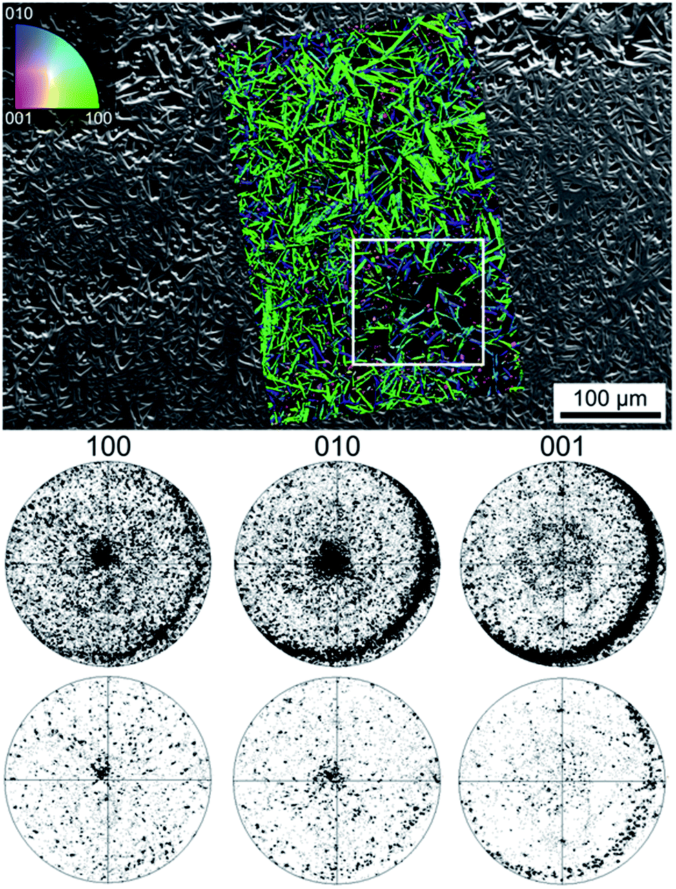 | ||
| Fig. 3 SEM-micrograph of a sample surface superimposed by the IPF + IQ-map of mullite crystals taken from an EBSD-scan performed on the area. The 100, 010 and 001 PFs of the entire scan as well as of the framed area only (below) are also presented. | ||
The microstructure inside cross sections of this sample is presented in Fig. 4 which features (a) an SEM-micrograph of the air/glass interface superimposed by the IPF + IQ-map of an EBSD scan and (b) an SEM-micrograph of the glass/ceramic interface. The micrographs show crystals matching the morphology of mullite grown in a glass melt using electrochemically induced nucleation.25,26 This needle morphology was described to be the result of a dendritic growth mechanism strongly hindered by a diffusion barrier during growth.25,26 Bright crystals implying zirconia in the glass melt are not observed near the glass/ceramic interface. The additionally presented 001-PF of the first 10 μm of the grown crystals shows a relatively high degree of orientations where the c-axes of the crystals are oriented parallel to the air/glass interface (circled by the dashed line). By contrast, these orientations are not observed in the PF representing crystal orientations occurring between 50 and 700 μm of the crystalline layer. It may be concluded, that the growth of mullite at this interface occurs via a strongly preferred surface nucleation with a certain preference of crystal orientation with the a- or b-axes perpendicular to the surface. Due to the needle-type growth of these crystals, they only grow along the surface but are not observed in the bulk. The crystals which do not nucleate with their c-axes parallel to the surface grow into the bulk and show only limited growth selection very similar to the growth observed in a glass melt after electrochemically induced nucleation.25,26
 | ||
| Fig. 4 SEM-micrographs of the cross section after annealing setup (a) using the annealing regime 1: (a) the interface air/glass and (b) the interface glass/ceramic. The IPF + IQ-map of part of a EBSD-scan performed on the cross section is superimposed on the SEM-micrograph to visualize orientations (same legend as Fig. 3). 001-PFs illustrating occurring orientations in different parts of the scan are also presented. | ||
EDX point analyses of the respective chemical composition were performed and the results were normalized to 100%. The glassy phase near the glass/ceramic interface showed a glass composition of 16.5MgO/27.7Al2O3/54.2SiO2/1.6ZrO2 in wt% while the composition of the bulk glass is 13.9MgO/35.3Al2O3/50.8SiO2 in wt% indicating depletion of the glass phase in Al2O3 and an enrichment in SiO2. The composition of a mullite crystal was determined to be 0.8MgO/71.7Al2O3/27.5SiO2 in wt% which is basically in agreement with the literature as mullite is an alumosilicate with the composition range (Al(4+2x)Si(2−2x)O(10−x)). In principle, solid solutions occur from x = 0 (Al2SiO5) to x = 1 (ι-Al2O3);28–32 with the typical composition range from 70.5 to 73.5 wt% Al2O3.33 While the 0.8 wt% MgO do not appear in this composition range, mullite can also incorporate a number of foreign cations34 including up to 0.5 wt% MgO.34 On the other hand it is also possible that the information volume of the EDX-analysis contained some of the glass matrix, i.e. below the crystal.
In order to confirm that the mullite formation at the surface is linked to the annealing regime, a polished piece of MAS-glass was annealed at 1050 °C for 1 h using a heating rate of 20 K min−1 and analyzed by EBSD. This only led to the surface crystallization of indialite while mullite was not observed.
Setup (a) combined with annealing regime 2
In a second experiment, setup (a) was combined with the annealing regime 2 because temperatures from 800 to 850 °C are frequently reported to promote nucleation in this system,22 i.e. this is frequently denoted as the nucleation temperature. Fig. 5 shows three XRD-patterns obtained from different parts of the sample: (a) from the air/glass interface, (b) from the glass previously adjacent to the glass/ceramic interface which was fractured due to the CTE mismatch during cooling and pattern (c) from the bottom of the setup, i.e. the ceramic side which was only in contact with a platinum/gold plate during annealing. The theoretical patterns of the detected phases are presented for comparison.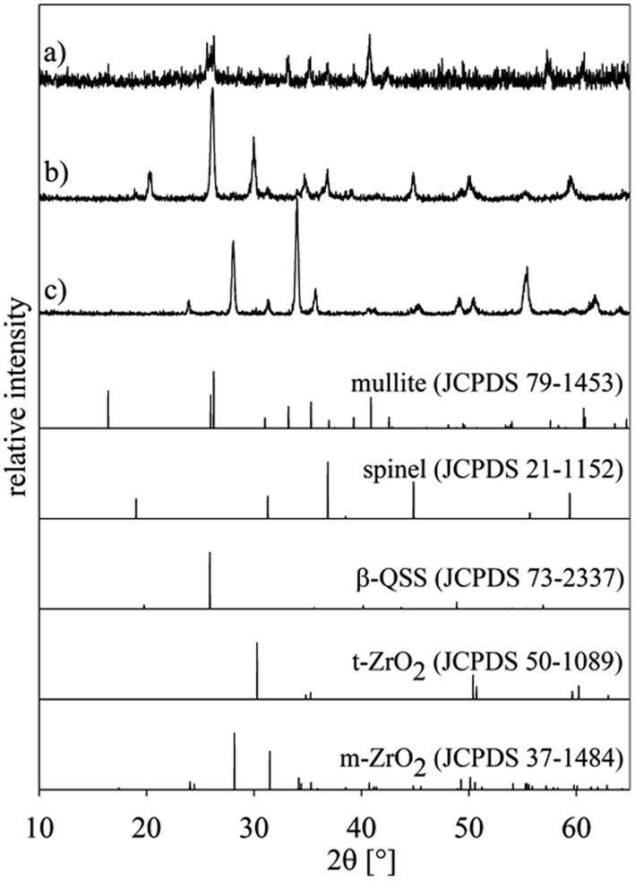 | ||
| Fig. 5 XRD-patterns of setup (a) annealed using regime 2: (a) air/glass interface, (b) the glass-ceramic side of the glass/ceramic interface and (c) bottom of the setup, i.e. only the ceramic. The theoretical patterns of detected phases are presented for comparison. | ||
While all the peaks in pattern (a) may be attributed to mullite, pattern (b) indicates a more complex system of phases. The peaks are attributable to the crystalline phases spinel (JCPDS 21-1152), β-QSS (JCPDS 73-2337), and tetragonal (or cubic) ZrO2 (JCPDS 50-1089). The latter could be stabilized by small quantities of MgO which could have diffused into the ZrO2. The presence of ZrO2 itself indicates that some of the ceramic was dissolved and subsequently diffused into the glass where it precipitated at the nucleation temperature. Pattern (c) shows monoclinic ZrO2 instead of the tetragonal ZrO2 of the original ceramic. As this side of the ceramic is not in contact with the glass, a diffusion of MgO into the ceramic can be excluded. The tetragonal ZrO2 stabilized by comparably small MgO concentrations only occurs in this phase if the grains are very small, usually with sizes below a few 100 nm.35,36 Probably the thermal treatment led to grain coarsening which allowed a phase transformation during subsequent cooling.
Setup (b) combined with annealing regime 3
As setup (b) was designed to prevent the fracture of the glass/ceramic interface despite the large differences in the CTE, XRD-patterns were not recorded from any interfaces of this sample. Instead, EBSD analysis was applied to the cross section covering the air/glass and glass/ceramic interfaces featured in Fig. 6. The area inside frame 1 is presented with greater detail in the SEM-micrograph of Fig. 6. Here the air/glass interface is located in the upper left corner while the glass/ceramic interface is shown at the bottom. EBSD-measurements performed on the air/glass interface revealed multiple crystals which could be reliably indexed as mullite. The superimposed IPF + IQ-map of an EBSD-scan shows that these crystals exhibit one orientation over large distances. Heavily disturbed needles26 are observed in addition to compact needles similar to those observed in Fig. 3. These disturbed structures probably result from the overall longer growth time and more varied growth conditions due to the two step annealing procedure. Other crystal phases were not detected by EBSD in this area.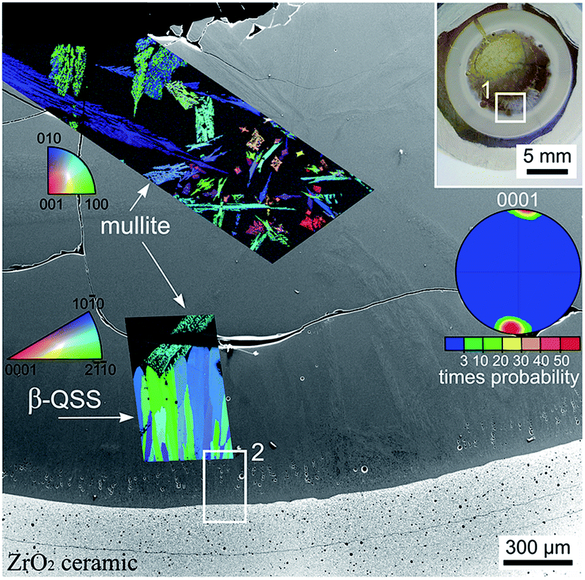 | ||
| Fig. 6 Photograph of a cross section of the setup (b) annealed using regime 3. The area in frame 1 is illustrated in greater detail by the SEM-micrograph which is superimposed by the IPF + IQ-maps of EBSD-scans performed on the air/glass interface as well as near the glass/ceramic interface. The 0001 PF of a texture calculated for the β-QSS phase is also presented. The area in frame 2 is presented in greater detail in Fig. 7. | ||
Another EBSD scan was performed near the glass/ceramic interface where an oriented layer of the β-QSS was detected. The IPF + IQ-map presented in Fig. 6 shows the aligned growth structures while their orientation is illustrated by the pole figure (PF) of an 0001 texture calculated from the scan. It shows that the c-axes of the growth structures are oriented parallel to the main direction of growth and parallel to the glass/ceramic interface.
The immediate glass/ceramic interface in frame 2 of Fig. 6 is presented in greater detail in Fig. 7(a) where the SEM-micrograph is again superimposed by the IPF + IQ-map of the reliably indexed data points of a performed EBSD-scan. A step size of 350 nm was used in combination with a binning of 4 × 4 to avoid EBSD-pattern degradation which limits the ability to analyze the β-QSS by EBSD. The ceramic side of the interface mainly contains monoclinic ZrO2 with no orientation preference. The inability to obtain reliably indexable EBSD-patterns from the glass/ceramic interface (black in the IPF + IQ-map) is neither due to EBSD-pattern degradation nor to sample preparation. It results from the extremely fine growth structures observed at the immediate interface highlighted in Fig. 7(b) which features an SEM-micrograph of the area framed in Fig. 7(a). Fig. 7(b) also shows that the β-QSS grows in the form of dendrites embedded in a matrix of a higher material contrast than the β-QSS.
 | ||
| Fig. 7 Setup (b), regime 3: (a) SEM-micrograph of the glass/ceramic interface superimposed by the phase + IQ-map of an EBSD-scan performed on the area. (b) The framed area is presented in greater detail. EBSD-patterns obtained from this region are presented below. | ||
While a high resolution EBSD-analysis of this region is problematic due to the small crystal size and the sensitivity of the β-QSS towards electron-beam damage, single EBSD-patterns of acceptable quality may be obtained from this region. The EBSD-patterns presented at the bottom of Fig. 7 were obtained from this interface and may be reliably indexed as 1 = β-QSS (based on ICSD file no. 24898), 2 = cubic or tetragonal ZrO2 and 3 = monoclinic ZrO2. It seems reasonable to assume that the patterns 4–6 originate from spinel considering that this phase was detected at the glass/ceramic interface using XRD, see Fig. 5. However, several attempts using different ICSD-files failed to supply a material file which produced systematically reliable indexing parameters for different patterns despite their easily discernible Kikuchi Bands. Comparably good results were obtained using the ICSD-file 31375 which describes cubic spinel of the composition MgAl2O4, but indexing remains problematic because, assuming a cubic phase, only the 111 pole is discernible in most patterns and the Kikuchi bands of other lattice planes are very weak. Monoclinic ZrO2 was only detected in the ceramic while tetragonal/cubic ZrO2 was detected in the ceramic as well as the adjacent glass-ceramic layer.
Due to the limits of EBSD-analysis in this area, STEM and EDXS analyses were performed at the glass/ceramic interface of an identically prepared sample. Fig. 8(a) shows a STEM micrograph of the crystallized layer adjacent to the ZrO2 ceramics (bottom left). The glass-ceramic side of the interface is presented in Fig. 8(b) with a higher magnification. According to EDXS analysis, the brightest growth structures, which imply a dendritic growth, are composed of ZrO2. The dark phase marked 1 in Fig. 8(b) is almost pure SiO2 while the phase marked 2 in Fig. 8(b) shows the composition of the β-QSS which was also indicated to grow in a dendritic morphology in Fig. 7.
 | ||
| Fig. 8 STEM dark field micrographs recorded from a FIB lamella cut from a sample of setup (b) annealed using the regime 3. The ceramic is located at the bottom left corner. | ||
A deeper insight into the phase composition of the glass-ceramic area close to the interface to the ZrO2 substrate is given in Fig. 9, where the element distribution mappings clearly show that the bright, dendritic structures contain Zr, Y and O. It may be concluded that these dendrites are composed of Y-stabilized Zirconia (YSZ). However, Y is not exclusively associated with YSZ alone, but also enriched in some areas of the residual glass. Mg and Al are mainly enriched in areas adjacent to the YSZ. As the undisturbed dendritic morphology can only form in a homogeneous matrix, it is justified to assume that YSZ crystallized first, depleting its vicinity of Zr and Y and enriching it in Al and Mg. Subsequently spinel (MgAl2O4) grew around the ZrO2 dendrites, from where it expanded into the residual glassy matrix, soaking up most of the Mg and Al from there during growth. The remaining residual glass therefore mainly consists of Si and O in this area of the sample. The framed areas 1 and 2 highlight that some Y occurs in the residual glass (frame 1: high Si content) and close to the spinel (frame 2: high Al and Mg content) which presumably accumulates Y at the growth front instead of incorporating it into the crystal.
 | ||
| Fig. 9 STEM micrograph (HAADF) and respective EDXS element distribution maps of Al, Mg, O, Si, Y and Zr recorded in the class-ceramic part of the sample, right next to the interface to the ZrO2 substrate. The superimposed frames highlight the location of Y in the residual glass (1) and adjacent to the spinel crystals (2). | ||
Fig. 10 shows an TEM micrograph of the ceramic side of the glass/ceramic interface. It contains comparably large grains of ZrO2 with twin-domain boundaries typical for monoclinic ZrO2 formed by a phase transformation from formerly tetragonal ZrO2.35 The glass melt notably corroded the ceramic which was 100% dense before annealing. It is assumed that corrosion occurred along the grain boundaries which led to an interpenetration of the outer ceramic layer; the glassy phase should hence be highly enriched in zirconia. The glassy phase between the zirconia grains in Fig. 10 is partially crystallized which is a direct evidence of the nucleating effect of zirconia.
 | ||
| Fig. 10 TEM bright field micrograph recorded from the ceramic side of the interface presented in Fig. 8. | ||
As illustrated above, both annealing without the nucleation temperature (regime 1) and with the nucleation temperature (regimes 2 and 3) leads to the crystallization of mullite at the air/glass interface. The XRD-pattern (a) in Fig. 2 and the corresponding EBSD-measurements indicate that oriented nucleation is observed. However, including the nucleation temperature into the annealing regime completely changes the results at the glass/ceramic interface. While it may be assumed that the glass melt corrodes the ceramic at 1500 °C allowing significant quantities of Zr4+ to dissolve into the glass, crystalline ZrO2 is only detected if the melt is cooled to the nucleation temperature before annealing at 1050 °C.
Including the nucleation step into the annealing process leads to four phases in the glass ceramic near the glass/ceramic interface: cubic or tetragonal ZrO2 in the form of small dendrites, monoclinic ZrO2, the β-QSS and the unindexed phase detected by EBSD which could be the spinel indicated by XRD and (S)TEM-EDXS analysis. A clearly discernible residual glassy phase is not detected.
Tetragonal (or cubic) and monoclinic ZrO2 were detected in the ceramic side of the glass/ceramic interface. The ZrO2 crystals in the glass-ceramic only occur close to the glass/ceramic interface. It should be assumed that some ZrO2 is dissolved from the ceramic during thermal treatment especially at the maximum temperature of 1500 °C and diffuses into the glass. While decreasing the temperature to the nucleation temperature, ZrO2 precipitates near the boundary to the ceramic material. It should be noted that this does not occur in the experiments performed with regime 1, because here the temperature was not decreased to 820–850 °C, but directly to the crystallization temperature of 1050 °C which did not lead to a precipitation of ZrO2. In these samples, neither zirconia nor the β-QSS were observed.
Conclusion
A glass in the system MgO/Al2O3/SiO2 in contact with a ZrO2 ceramic was heated to a temperature of 1500 °C, then to 820–850 °C and subsequently to 1050 °C where it was held for 1 h before cooling to 20 °C. The following phases were identified in the glass near the glass/ceramic interface: ZrO2 both in the tetragonal and in the monoclinic modification, a β-quartz solid solution and spinel. At some distance from the ZrO2 ceramic, the only detected crystalline phase was the highly oriented β-QSS with the c-axis aligned parallel to the primary growth direction. Only mullite was detected at the air/glass interface.By contrast, only mullite formed at both interfaces in a sample heated directly to 1050 °C after the initial period at 1500 °C. Oriented nucleation of mullite with the (a,b) axis perpendicular to the surface was observed at the air/glass interface during these experiments. The thermal treatment at 820–850 °C leads to the formation of zirconia which triggers the crystallization of the β-QSS.
Acknowledgements
This work was supported by Deutsche Forschungsgemeinschaft (DFG) in Bonn Bad Godesberg (Germany) via project nr. RU 417/14-1 and project nr. Ho 1691/5-1. We would like thank Susanne Hübner (Fraunhofer IMW, Halle) for the FIB lamella preparation.References
- N. Diaz-Mora, E. D. Zanotto, R. Hergt and R. Müller, J. Non-Cryst. Solids, 2000, 273, 81 CrossRef CAS.
- P. Wange, T. Höche, C. Rüssel and J.-D. Schnapp, J. Non-Cryst. Solids, 2002, 298, 137 CrossRef CAS.
- W. Zdaniewski, J. Mater. Sci., 1973, 8, 192 CrossRef CAS.
- H. Shao, K. Liang, F. Zhou, G. Wang and A. Hu, Mater. Res. Bull., 2005, 40, 499 CrossRef CAS.
- W. Zdaniewski, J. Am. Ceram. Soc., 1975, 58, 163 CrossRef CAS.
- M. McCoy, W. Lee and A. H. Heuer, J. Am. Ceram. Soc., 1986, 69, 292 CrossRef CAS.
- O. Dargaud, G. Calas, L. Cormier, L. Galoisy, C. Jousseaume, G. Querel and M. Newville, J. Am. Ceram. Soc., 2010, 93, 342 CrossRef CAS.
- M. Dittmer, M. Müller and C. Rüssel, Mater. Chem. Phys., 2010, 124, 1083 CrossRef CAS.
- C. Patzig, M. Dittmer, T. Höche and C. Rüssel, Cryst. Growth Des., 2012, 12, 2059 CAS.
- A. Hunger, G. Carl, A. Gebhardt and C. Rüssel, J. Non-Cryst. Solids, 2008, 354, 5402 CrossRef CAS.
- A. Hunger, G. Carl, A. Gebhardt and C. Rüssel, Mater. Chem. Phys., 2010, 122, 502 CrossRef CAS.
- A. Hunger, G. Carl and C. Rüssel, Solid State Sci., 2010, 12, 1570 CrossRef CAS.
- G. H. Chen and X. Y. Liu, J. Alloys Compd., 2007, 431, 282 CrossRef CAS.
- G. H. Chen, J. Mater. Sci.: Mater. Electron., 2007, 18, 1253 CrossRef CAS.
- L. R. Pickney and G. H. Beall, J. Non-Cryst. Solids, 1997, 219, 219 CrossRef.
- A. Katzschmann and P. Wange, Glass Sci. Technol., 1995, 68, 111 CAS.
- C. H. Chen, J. Mater. Sci., 2007, 42, 7239–7244 CrossRef.
- S.-B. Sohn and S.-Y. Choi, J. Non-Cryst. Solids, 2001, 282, 221–227 CrossRef CAS.
- A. Gawronski, C. Patzig, T. Höche and C. Rüssel, CrystEngComm, 2013, 15, 6165 RSC.
- A. Gawronski and C. Rüssel, J. Mater. Sci., 2013, 48, 3461 CrossRef CAS.
- W. Höland, P. Wange, G. Carl, W. Vogel, E. Heidenreich and H. Erxleben, Silikattechnik, 1984, 35, 181 Search PubMed.
- M. Dittmer and C. Rüssel, J. Biomed. Mater. Res., Part B, 2012, 100, 463 CrossRef PubMed.
- W. Vogel, Glass Chemistry, Springer, Berlin/Heidelberg, 2nd edn, 1994 Search PubMed.
- C. Patzig, M. Dittmer, A. Gawronski, T. Höche and C. Rüssel, CrystEngComm, 2014, 16, 6578 RSC.
- W. Wisniewski, R. Carl, G. Völksch and C. Rüssel, Cryst. Growth Des., 2011, 11, 784 CAS.
- W. Wisniewski, R. Carl and C. Rüssel, CrystEngComm, 2014, 16, 1192 RSC.
- W. Wisniewski, K. Otto and C. Rüssel, Cryst. Growth Des., 2012, 12, 5035 CAS.
- W. R. Cameron, Am. Mineral., 1977, 62, 747 CAS.
- R. J. Angel, R. K. McMullan and C. T. Prewitt, Am. Mineral., 1991, 76, 332 CAS.
- L. H. Merwin, Phys. Chem. Miner., 1991, 18, 47 CrossRef CAS.
- C. Paulmann, S. H. Rahman and S. Strothenk, Phys. Chem. Miner., 1994, 21, 546 CrossRef CAS.
- P. Rehak, G. Kunath-Fandrei, P. Losso, B. Hildmann, H. Schneider and C. Jaeger, Am. Mineral., 1998, 83, 1266 CAS.
- R. F. Davis and J. A. Pask, Am. Ceram. Soc. Bull., 1972, 55, 525 CrossRef CAS.
- H. Schneider, J. Schreuer and B. Hildmann, J. Eur. Ceram. Soc., 2008, 28, 329 CrossRef CAS.
- R. C. Garvie, J. Phys. Chem., 1965, 69, 1238 CrossRef CAS.
- T. Höche, M. Deckwerth and C. Rüssel, J. Am. Ceram. Soc., 1998, 81, 2029 CrossRef.
| This journal is © The Royal Society of Chemistry 2015 |