 Open Access Article
Creative Commons Attribution 3.0 Unported Licence
Collective ordering of colloids in grafted polymer layers†
Tine
Curk
*a,
Francisco J.
Martinez-Veracoechea
a,
Daan
Frenkel
a and
Jure
Dobnikar
*ab
aDepartment of Chemistry, University of Cambridge, Lensfield Road, CB2 1EW, Cambridge, UK. E-mail: tc387@cam.ac.uk
bDepartment for theoretical physics, Jožef Stefan Institute, Jamova 39, 1000 Ljubljana, Slovenia. E-mail: jd489@cam.ac.uk
First published on 25th April 2013
Abstract
We present Monte Carlo simulations of colloidal particles pulled into grafted polymer layers by an external force. The insertion free energy for penetration of a single colloid into a polymer layer is qualitatively different for surfaces with an ordered and a disordered distribution of grafting points and the tendency of colloidal particles to traverse the grafting layer is strongly size dependent. In dense colloidal suspensions, under the influence of sufficiently strong external forces, colloids penetrate and form internally ordered, columnar structures spanning the polymer layer. The competition between the tendency for macro-phase separation of colloids and polymers and the elastic-like penalty for deforming the grafted layer results in the micro-phase separation, i.e. finite colloidal clusters characterized by a well-defined length scale. Depending on the conditions, these clusters are isolated or laterally percolating. The morphology of the observed patterns can be controlled by the external fields, which opens up new routes for the design of thin structured films.
I Introduction
Grafted polymer layers can prevent the deposition of colloidal particles on solid surfaces, which is exploited in various applications like colloidal stabilization, anti-fouling surfaces1 and in biomedicine.2 Biological surfaces such as the lining of the intestine or the blood vessel walls are coated with polymers that inhibit the absorption of too large particles. In several other applications, the insertion of colloids or nano-particles into polymer layers is exploited in order to fabricate functional responsive materials.3 The physical properties of grafted polymer layers are governed by the configurational entropy of tethered polymers and have been studied extensively for different grafting and solvent conditions.4–8 The penetration of particles into polymer layers has been recently addressed in theoretical and numerical studies.9–15 Colloids soluble in polymers penetrate up to a depth determined by their size,16 while insoluble particles form aggregates, which are expelled from the brush after reaching a critical size.17 The polymer-mediated colloidal interactions are typically of the order of kBT15,18 (i.e., comparable to the entropic terms of the colloids), therefore, the colloid–polymer mixtures are inherently disordered. In order to exploit the weak polymer-induced interactions for the assembly of ordered patterns, the colloidal translational degrees of freedom need to be constrained, e.g. by applying external forces. However, little is known about collective particle ordering in a brush under the influence of a constant force.10Here we report Monte Carlo computer simulations of polymer-insoluble particles in grafted polymer layers. We demonstrate that sufficiently strong external forces give rise to collective ordering with a rich variety of morphologies. We studied polymer layers under good solvent conditions between the “mushroom” and the “brush” regime,10 with the mean spacing between the grafting points (i.e. the de Gennes blob size4) being roughly similar to the radius of gyration of the polymers and to the colloid diameter. The polymers generally repel the particles from the surface. We find that the repulsion at a given grafting density is largest when the distribution of the grafting points at the surface is ordered, while in the case of disordered grafting with large-enough monomer density fluctuations at the surface, the free energy profile resembles a barrier and is attractive close to the surface. This enables reversible adsorption of particles and their slow release. The nature of the constant external force suitable for pulling the colloids into the polymer layer depends on the particle size: large micro-particles can sediment under the influence of gravity, which, however, plays no role in the case of polymers or nanoparticles in aqueous solutions. An effect equivalent to pulling by gravity would be obtained by placing the system in a centrifuge.
II Model
The system comprises of polymer chains end-grafted to a flat surface and hard-sphere colloids with a diameter σ immersed in a neutral good solvent. For any pair of colloids the interaction potential is given by:with β ≡ 1/kBT being the inverse thermal energy and r is the center-to-center distance of the particles. The particle diameter σ is taken as the unit of length in the simulations. Apart from the hard-core, the colloids do not interact with each other directly but via polymer-mediated interactions. The colloids are additionally subject to a constant external force fg. Regardless of the physical nature of the external force, its significance is measured by the ratio of potential versus thermal energy: g′ = fgσ/kBT. In the case of gravity, g′ = mgσ/kBT ∝ σ4, where σ is the diameter and m the effective mass of the colloids in the solvent. Typical values, say for micron-size silica colloids in water, are around g′ ≈ 2. Scaling down to 100 nm, g′ ≈ 10−4. For a single colloid, the free energy profile F(z) is the sum of its potential energy in the external field and the insertion free energy penalty Fp(z) for disturbing the polymer layer:
 | (1) |
The linear potential energy term decouples from the polymeric degrees of freedom, and Fp(z) holds the key to understanding the penetration of a single colloid into a polymer layer.
In a good solvent the polymers can be modelled as self-avoiding random walks. We follow a coarse-grained model19 where the polymer chains are represented by soft repulsive blobs with a radius of gyration rb. Each chain is composed of lp blobs, which are connected via harmonic springs:
| βUch = 0.534(r/rb − 0.730)2. | (2) |
Individual blobs repel each other via a Gaussian repulsion
 | (3) |
| βUbc = 3.20e−4.17(r/rb−0.50) | (4) |
The grafting density ![[small rho, Greek, tilde]](https://www.rsc.org/images/entities/i_char_e0e4.gif) = Np/Rg2 determines whether the polymer layer is in the dilute “mushroom” (
= Np/Rg2 determines whether the polymer layer is in the dilute “mushroom” (![[small rho, Greek, tilde]](https://www.rsc.org/images/entities/i_char_e0e4.gif) < 1) or in the dense “brush” scaling regime (
< 1) or in the dense “brush” scaling regime (![[small rho, Greek, tilde]](https://www.rsc.org/images/entities/i_char_e0e4.gif) ≳ 3).20,21 The relevant physical length scale in the mushroom regime is the radius of gyration Rg of the chains, while in the brush regime it is the so-called de Gennes blob: ξ ∝ ρ−1/2.4 All our simulations are in the intermediate regime where the two length-scales are similar ξ ≈ Rg. In the following, rather than per Rg2, we will express the grafting density as the number of anchoring points per colloidal diameter squared, therefore ρ =
≳ 3).20,21 The relevant physical length scale in the mushroom regime is the radius of gyration Rg of the chains, while in the brush regime it is the so-called de Gennes blob: ξ ∝ ρ−1/2.4 All our simulations are in the intermediate regime where the two length-scales are similar ξ ≈ Rg. In the following, rather than per Rg2, we will express the grafting density as the number of anchoring points per colloidal diameter squared, therefore ρ = ![[small rho, Greek, tilde]](https://www.rsc.org/images/entities/i_char_e0e4.gif) Rg2/σ2. We will explore the regime 0.5 < ρ < 5, where the probability of inserting a colloid with σ ≈ Rg is non-vanishing. We first describe the model and simulations on single-colloid insertion, followed by a study of collective ordering in dense colloidal systems.
Rg2/σ2. We will explore the regime 0.5 < ρ < 5, where the probability of inserting a colloid with σ ≈ Rg is non-vanishing. We first describe the model and simulations on single-colloid insertion, followed by a study of collective ordering in dense colloidal systems.
III Single colloid insertion
We have used the coarse-grained model described above in Monte Carlo simulations and evaluated the single-particle insertion free energy profiles Fp(z) for a wide range of parameters lp and ρ by biasing the sampling in the z coordinate with the Wang–Landau technique.22A Ordered and disordered surfaces
It is important to realize that the insertion free energy for a colloidal particle is determined by both the mean monomer density and the monomer density fluctuations: at surfaces with significant variations in the local anchoring density, large regions void of polymers exist, which makes it easier to insert a single colloid as compared to the uniformly anchored surfaces with equal average grafting density. We have investigated this by computing Fp(z) for polymer layers with three different spatial distributions of the grafting points: “quenched disorder” (random Poissonian process), “annealed disorder” (random points, relaxed before the simulation), and “order” (grafting points on a square lattice). Quenched and annealed distributions roughly correspond to the experimental conditions: two main protocols for fabricating polymer brushes are grow from and grow to the surface. In the grow from procedure, the distribution of anchors is likely to be random, since it is determined by the positions where the monomers first adsorbed to the surface. In grow to methods the polymers are separately prepared and then attached to the surface from the solution. We argue that the arrangement of the anchoring points in such a process is close to the annealed disorder. However, with the current methods of brush fabrication, it is difficult to realize an ordered arrangement of the anchors.As demonstrated in Fig. 1(a), the free energy profiles in the three grafting arrangements are qualitatively different: in the ordered case the free energy monotonically decreases with height,6,10 while in the disordered case it features a barrier (also reported in ref. 9 and 12). In the inset, Fig. 1(b), we plot the 2D distribution of the hole sizes23 for the three arrangements, which clearly illustrate the above discussion. The difference between the quenched and annealed disorder is rather small, which is due to the fact that the anchoring points (monomers) are vanishingly small compared to the polymer Rg and therefore do not repel each other as the blobs do in our coarse-grained model. Close to the grafting surface the monomer fluctuations are “frozen” because the anchoring points are immobile, while away from it they relax. Any effect of the surface-imposed density fluctuations should therefore vanish at a height roughly equal to Rg – well confirmed in Fig. 1(a). In the experimentally relevant situations (disordered grafting), we therefore expect to observe a maximum in the free energy profile around z ≈ Rg and a metastable minimum at the surface. A strong-enough external force can transform the metastable local minimum at the surface into a stable free-energy minimum.
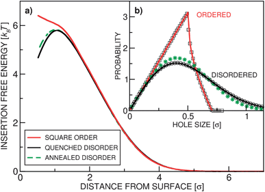 | ||
| Fig. 1 Isolated colloids in polymer layers with grafting density ρ = 1.0 and number of blobs per chain lp = 20. (a) The insertion free energy profile Fp(z) for three realizations of the surface grafting: quenched disorder (black solid line), square crystalline order (red solid line), and annealed disorder (green dashed line). (b) The distribution of (2D) hole sizes for the three scenarios. The solid lines represent the analytically derived expressions (see ESI†), symbols are numerically determined. For both cases of disordered grafting there is an appreciable probability of finding large holes, while the ordered surfaces, characterized by small density fluctuations, have a cut-off in the hole size. | ||
In Fig. 2(a) we present the insertion free energy profiles for various parameters in the case of disordered grafting. We also show (Fig. 2(b)) the matching monomer density profiles, which are monotonic (apart from the oscillating behavior very close to the surface due to the finite size of the blobs). In Fig. 2(c)–(e) the scaling of the position and height of the free energy maximum are analyzed. The barrier height Fmax scales linearly with ρ and with σ2 (see also ESI†); in our system it is typically of the order of 10 kBT.
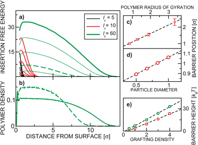 | ||
| Fig. 2 (a) The insertion free energy profiles for disordered grafting. Each of the three family of curves show insertion free energy for various ρ = 0.5, 1, 2, 3, 4. (b) The monomer (blob) vertical density profile for lp = 60 and ρ = 4 (bold green), ρ = 1 (dashed green). The position of the free energy barrier (in the case of disordered grafting) as a function of (c) polymer size and (d) colloid size is presented. (e) shows the barrier height as a function of the grafting density for lp = 10 (red) and lp = 60 (green). | ||
B Reversible adsorption and particle sorting
The existence of the free energy maximum has important consequences: it enables reversible adsorption and slow release of the colloids, as well as particle sorting according to their size. The adsorption and release can be controlled by varying either the external potential or the grafting density. Fig. 3(a) shows the probability distributions for colloids pulled by a constant external force g′ = 3 into polymer layers characterized by disordered grafting with varying grafting densities ρ. In the absence of the polymer layer a colloidal particle would sediment under the constant force with the barometric height profile (black solid line). At small grafting densities the stable free energy minimum is at the surface (red and green lines). Interestingly, in such a case, the colloid is confined closer to the surface than in the absence of the polymer layer24 (see the inset, Fig. 3(b)). This can play an important role in systems with diffusion-limited interactions: enhanced confinement of particles increases their meeting probabilities and thus the reaction rates. In ref. 12 the effect of a polymer brush on the protein folding process has been reported, which can be quite well understood in light of our findings. For very dense grafting (orange solid line in Fig. 3), the particle cannot penetrate the brush, while for the intermediate values we observed a bimodal height distribution (blue solid line): the colloid abruptly changes from the adsorbed to the released state and is not likely to be found in the middle of the layer. Both the grafting density ρ and the magnitude of the external force can be manipulated by varying the size of the colloids. In Fig. 4 we plot the total free energy and height distribution for colloids of three different sizes in the gravitational field. The smallest particles gather on top, the largest ones sediment, while the medium-size colloids are distributed in a bi-modal way. This single-colloid picture also governs the density profiles in dilute systems as seen in the simulation snapshots in Fig. 4(c). The results can therefore be used to design a practical particle-size sorting application or to prevent clustering in solutions.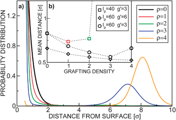 | ||
| Fig. 3 (a) Normalized probability distributions p(z) = exp(−βF(z))/∫exp(−βF(z))dz for lp = 40, g′ = 3 and various grafting densities ρ = {0, 1, 2, 3, 4}. (b) The mean distance of the centre of the colloid from the surface z as a function of the grafting density ρ at various parameters lp and g′. Due to the hard-core of the colloids, the lowest accessible distance is z = 0.5. The dotted lines are guides for the eye. | ||
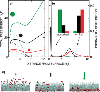 | ||
| Fig. 4 (a) Total free energy of sedimenting colloidal particles obtained by simulations at lp = 40 and ρ = 1.0 for silica colloids with three sizes: σ1 = 0.67 μm (red line), σ2 = 1.00 μm (black line), and σ3 = 1.33 μm (green line). Respectively, g′2 = 2.0 (corresponds to micrometer sized silica particles in water), g′1 = 0.40 and g′3 = 6.3 (the grafting density is equal in all three cases and defined as ρ = Np/σ22). The dashed lines represent the insertion free energy Fp(z). (b) Normalised height distribution P(z) ∝ e−βF(z) for the same system. The histograms illustrate the probability of finding the colloids adsorbed to the surface or above the brush (left set of histograms: z < Rg and right set: z > Rg). (c) Snapshots from Monte Carlo simulations of dilute colloidal suspensions under conditions corresponding to (a) and (b). | ||
The free energy barrier height scales with σ2, while in the case of gravity, the external force scales with the particle volume (σ3). Therefore, larger particles will preferentially sediment on the surface. In case other types of external forces are applied that do not depend on the particle size (this is the case for, e.g., osmotic gradients), the quadratic scaling Fmax ∝ σ2 results in an inverted size selectivity: at a given value of the pulling force, only sufficiently small nano-particles will penetrate, a scenario particularly important in biology. The size-selectivity for electric field driven insertion might be much less pronounced than in the case of gravity, since the electric charge typically scales with the particle surface (σ2), which cancels out with the barrier height scaling. It must be noted that electromagnetic forces would also induce particle interactions, thus deviating from the hard-sphere model used in this work.
IV Insertion of multiple colloids
When many colloids are inserted, the polymers mediate effective many-body interactions among them and the insertion free energy in general depends on the positions of all particles. To explore such multi-particle systems we have performed Grand-canonical Monte Carlo simulations with colloidal particles coupled to a reservoir with a fixed chemical potential μ at various polymer grafting densities, chain lengths, particle concentrations and external forces. We started with empty polymer layers and slowly added particles from the reservoir. The attempted insertions were at random positions. However, most accepted insertions were on top of the brush and the colloids later diffused into the layer. At large ρ the system is frequently trapped in metastable states and the observed structures depend on the rate of the attempted insertions. At high rate, colloids can form a layer on top – compressing the polymer layer and creating large barriers for any colloid to penetrate. For slow-enough insertion, the colloids inserted on top have enough time to explore the free energy landscape and the system can reach the thermal equilibrium.At any given value of the external field strength g′ and polymer size lp, there is a “critical” value of the grafting density ρ = ρ0, at which the external pressure is balanced by the repulsion of the polymers. The colloids can only penetrate the polymer layers with small-enough grafting densities ρ < ρ0. The insertion of multiple colloids into a polymer layer is a many-body problem: when one is inserted, it compresses the polymers and increases their effective density that is felt by the next colloid. In our simulations, μ controls the equilibrium number of colloids within the layer. Note that, due to a constant external force, the chemical potential of inserted colloids depends linearly on their height; we chose to define the chemical potential at the bottom surface (z = 0). For small μ, the penetrating particles form clusters at the bottom surface that ”grow” towards the top of the brush as μ increases. Fig. 5 compares typical snapshots on disordered and ordered surfaces. At small μ there is a difference: the shape of the clusters above the ordered surfaces is narrower at the bottom (resembling a table-top) due to the strong repulsion of colloids from the surface, while in the case of disordered grafting the local free energy minimum enables pyramid-like structures. In both cases, however, similar structures emerge as μ is increased: clusters with a uniform vertical profile are formed – spanning the brush from bottom to top resembling straight cylindrical towers. Once such towers reach the critical conditions for fully loaded layers, increasing the chemical potential further leads to accumulation of colloids on top of the layer.
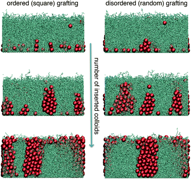 | ||
| Fig. 5 Cluster growth as a function of the number of colloids (chemical potential) in the system. The sequence on ordered (left-hand side) and disordered (right-hand side) surfaces is depicted. When the number of inserted colloids is small, “pyramid” and “table-top” structures are formed on disordered and ordered surfaces, respectively. Adding more particles, in both cases “critical” clusters with uniform vertical profiles spanning the polymer layer are formed. The number of blobs per chain is lp = 40, the anchoring density ρ = 4.0, g′ = 6.0. The chemical potentials (μ) and number densities (per unit area) of colloidal particles (n) corresponding to the three rows of snapshots are: (top) βμ1 = 41, ncolsq = 0.54, ncolrnd = 0.82; (middle) βμ2 = 46, ncolsq = 1.91, ncolrnd = 1.98; (bottom) βμ3 = 51, ncolsq = 3.20, ncolrnd = 3.23. | ||
The maximum amount of colloids that can be inserted into a layer depends on the grafting density: it is zero at the ρ ≥ ρ0 and grows linearly with decreasing density. Once the maximum load is achieved, the average density of polymers in the space around the colloids equals the critical value, regardless of the grafting density ρ. Consequently, the thickness of a fully loaded layer should not depend on the grafting density. Insertion free energy scales approximately linearly with the brush grafting density (see Fig. 2 and a discussion in ESI†), so the polymer pressure should also scale approximately linearly with the grafting density. External (hydrostatic-like) pressure scales linearly with the strength of the force field g′ and brush height hb, the balance of pressures gives
| ρ0 = κhbg′. | (5) |
The proportionality constant κ in general depends on the solvent properties and the polymer and colloidal interactions. In our model, κ is defined by the choice of the interaction potentials, which represents hard-sphere colloids and self-avoiding walk polymers. From the simulation data (see ESI†), we obtain κSAW ≈ 0.11. In experiments, as long as they are in the good solvent regime and there are no specific colloid–colloid or colloid–polymer interactions, the value of κ should be similar. For large-enough external forces, the value of the critical effective density is well in the brush scaling regime. Therefore, the height of the fully loaded layer is expected to scale as hb ∝ lpρ0ν with the exponent ν = 0.35 for self-avoiding chains.4 Using eqn (5) this leads to an interesting scaling relationship for the fully loaded brush height:
 | (6) |
From the simulations such scaling is roughly confirmed. Insertion of colloids can thus potentially be used to control the thickness of polymer brushes: experimentally, adding an excessive amount of colloids and washing off the ones above the brush could be attempted.
Given the uniform vertical profiles observed in the colloidal clusters (Fig. 5), the particle load is directly correlated with the colloidal surface coverage η of the two-dimensional horizontal cross-sections:
 | (7) |
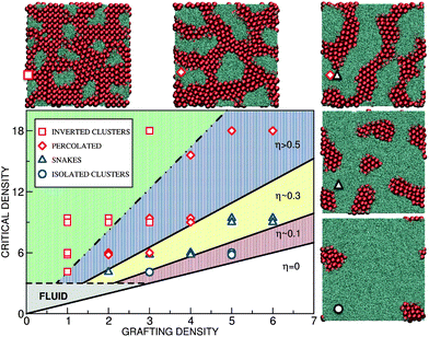 | ||
| Fig. 6 Phase behavior as a function of the polymer grafting density and the external pressure. Various lateral patterns are depicted by symbols: isolated towers (blue circles), “walls” (blue triangles), percolating structures (red diamonds) and inverted towers (red squares). The black lines separating the phases are lines of constant surface coverage η. The white lower region is “super-critical”: no colloids penetrate the brush. The grey-shaded region depicts the regime where the colloids do penetrate but the effective polymer density is too small to induce particle ordering. The extent of the fluid region depends on the physical parameters, especially on the colloidal excess density and size. Presented here is the case of σ = 1 μm silica colloids in water; for smaller colloids the boundary of the fluid region would shift upwards. Top-view snapshots from the simulations displaying the lateral morphology are shown at the side and marked by the same symbols. The critical density is ρ0 = 6.0 with g′ = 6.0, lp = 40. | ||
V Lateral patterns
With the simple arguments presented above we can explain the colloidal surface coverage for various parameters. In order to discuss the lateral arrangement, however, we need to go beyond the simple picture and consider two major physical mechanisms. The first mechanism is the polymer–colloid separation, which is due to the entropic restriction on polymer configurations near colloids, and favours the macro-phase separation. The separation is spatially limited because of the fixed grafting points. The two opposing mechanisms result in various finite-size lateral patterns with a well-defined length scale. In Fig. 6 we present the phase diagram as a function of the grafting density ρ and the critical density ρ0 ∝ g′hb. We have investigated both ordered and disordered surfaces and observed no important differences in the lateral morphology. Different structures observed in the simulations are depicted by symbols and their phase boundaries are approximately marked by the solid lines of constant colloidal surface coverage η. At large grafting density (low η), the colloidal clusters are isolated circular towers, upon reducing ρ they elongate into wall-like objects, percolating structures, and finally inverted towers at very low ρ. The morphologies are quite robust. For parameters in Fig. 6, the characteristic length-scale is L0 ≈ 5σ. Interestingly, L0 does not depend on the grafting density but scales with lp and is roughly equal to half of the brush height, L0 ≈ hb/2.In order to theoretically understand the micro-phase separation leading to these various patterns we consider two mechanisms governing the stability of colloidal clusters. Based on the simulations, the clusters are assumed to be vertically uniform and spanning the entire polymer layer. The polymers are excluded from the volume occupied by the colloids, which increases their effective density in the available space to the critical density ρ0. We will specifically focus on the transition from symmetric towers to the elongated wall-like clusters. The towers have a circular cross-section with radius r. For simplicity we assume that a “wall” is composed of the middle part of length l with a rectangular cross-section and two semicircular ends (radius r). A generalized cluster is characterized by the width 2r and the aspect ratio α ≡ 1 + l/2r (α = 1 for the towers and α > 1 for the walls).
The first contribution to the free energy penalty is the “excluded volume” term Fex. We assume that the polymers are excluded from the volume occupied by the cluster and from an additional “depletion” layer with the thickness γ around it – modelling the entropic penalty of confining the polymer configurations near a solid object. The free energy penalty due to the excluded volume is proportional to the total volume inaccessible to the polymers:
| Fex/kBT = Cexρ0hb[r2fα + γr(fα + π)]. | (8) |
 . The proportionality constant ρ0Cex specifies the free energy penalty per unit volume for inserting a cluster into the brush. It can be determined from the insertion free energy plots in Fig. 2. The typical value for the parameter regime in our work is Cex ≈ 4kBT/σ (for details see ESI†). The excluded volume contribution favors macro-phase separation of colloids and polymers in order to minimize the depletion penalty.
The second contribution to the free energy penalty is the “squashing” term Fsq, an elastic-like term that measures the entropy loss of the parts of the polymer chains squashed beneath the cluster. The elastic penalty is assumed to be proportional to the length of the squashed chains, e.g. kBT per squashed de Gennes blob. We also assume that the polymer chain extends radially (with respect to the center of tower) from its grafting point in order to minimize the squashed length. For the towers,  , where Csq is a constant that specifies the squashing entropic penalty per unit length of a chain, which is (see ESI†)
  . The total free energy penalty F = Fex + Fsq for a small number N of generalized clusters is
 | (9) |
Minimizing eqn (9) with respect to N, r and α subject to a constraint of fixed total colloid area, Scol = Nr2fα, we obtain the optimal number, size and shape of the clusters (Fig. 7): at small cluster volumes hbScol, a single tower with circular cross-section is formed. The theory predicts that the width of the circular tower grows from zero to L0 ≈ 4.6σ with an increasing cluster volume. In reality, clusters thinner than L0 are not layer-spanning (see Fig. 5) and we only expect to observe circular layer-spanning towers of width L0. Larger clusters then elongate into wall-like objects – keeping their width constant. The theory correctly predicts the characteristic length scale L0 and the shape of small clusters.
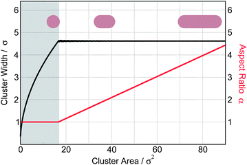 | ||
| Fig. 7 The typical width (black line) and the optimal aspect ratio α (red line) as a function of the surface cross-section of the clusters predicted by minimizing the free energy eqn (9) assuming Cex = 4.0kBT/σ, Csq = 2.4kBT/σ and γ = 0.2σ. The smallest layer-spanning clusters are isotropic towers with the width of L0 ≈ 4.6σ, while clusters larger than that form elongated walls. Clusters smaller than hbL0 (shaded region) are not layer-spanning in the simulations. | ||
Deriving the final expression, we made two approximations. First, we assumed ρ ≈ ρ0. While this assumption is valid for isolated clusters (η → 0), it does not hold at larger colloid filling fractions. It overestimates the squashing term and consequently favors circular towers over elongated walls. The second approximation is the assumption that the effective polymer density is equal to ρ0 everywhere in the interstitial space between clusters. This is not strictly true since polymers are anchored and the blob density should be higher near the clusters than further away. The approximation neglecting this fact favors elongated over circular clusters. Our hand waving argument is that the two effects partially cancel out – extending the validity of eqn (9) to finite values of η. The good agreement of the theoretical predictions with simulations at small values of η supports this argument. To quantitatively predict the stability of percolated structures at large η, however, a more refined approach, explicitly taking into account the two corrections mentioned above, would be needed. The micro-phase separation happens when the squashing constant Csq is positive. If, on the other hand, anchoring points were mobile on the surface, the polymers would not get squashed because they could simply escape from beneath the clusters. This is equivalent to setting Csq = 0, where the theory predicts r → ∞, e.g. a macroscopic phase separation. This was indeed observed in the simulations.
VI Conclusion
Our results provide insight into collective ordering of particles in polymer layers, which is of key relevance for understanding various biological processes, and to design novel materials and applications. We predict that grafted surfaces can be efficiently used as a sorting device for polydisperse particles or particle aggregates, as well as to control the rates of chemical reactions. A possible physical realization of our model is thin metallic films with metal-coated micro-particles pulled into grafted layers by gravity. The collective ordering of colloids is governed by the interplay between the macro-phase separation and elastic deformation of the polymer layer. The resulting patterns with morphologies reported in this work are expected to have unique mechanical, charge or heat transport properties. If mechanical stress can be applied to stretch or bend the substrate, the grafting density and the morphology of the emerging structures can be externally manipulated, which opens up new possibilities of designing responsive applications (e.g. smart glasses25 and miniature sensors26). The observed morphologies and the theoretical insight should provide useful insight for characterization of grafted surfaces.Acknowledgements
We acknowledge enlightening discussions with O. Scherman, B. M. Mognetti, P. Varilly, S. Angioletti-Uberti, and M. Miller. This work was supported by the European Union through FP7 grants ARG-ERC-COLSTRUCTION 227758 and ITN-COMPLOIDS 234810, and by the Slovenian research agency (P1-0055). TC acknowledges the support of the Erasmus work placement scheme.References
- G. D. Bixler and B. Bhushan, Biofouling: lessons from nature, Philos. Trans. R. Soc., A, 2012, 370, 2381–2417 CrossRef CAS.
- N. Ayres, Polymer brushes: Applications in biomaterials and nanotechnology, Polym. Chem., 2010, 1, 769–777 RSC.
- M. A. Cohen Stuart, et al., Emerging applications of stimuli-responsive polymer materials, Nat. Mater., 2010, 9, 101–113 CrossRef.
- P.-G. de Gennes, Scaling concepts in polymer physics, Cornell University Press, 1979 Search PubMed.
- S. T. Milner, T. A. Witten and M. E. Cates, Theory of the Grafted Polymer Brush, Macromolecules, 1988, 21, 2610–2619 CrossRef CAS.
- M. Murat and G. S. Grest, Structure of a grafted polymer brush: a molecular dynamics simulation, Macromolecules, 1989, 22, 4054–4059 CrossRef CAS.
- B. Zhao and W. J. Brittain, Polymer brushes: surface-immobilized macromolecules, Prog. Polym. Sci., 2000, 25, 677–710 CrossRef CAS.
- J. Rühe, et al., Polyelectrolyte Brushes, Adv. Polym. Sci., 2004, 165, 79–150.
- V. Ermilov and A. Lazutin, Colloids in Brushes: The Insertion Free Energy via Monte Carlo Simulation with Umbrella Sampling, Macromolecules, 2010, 43, 3511–3520 CrossRef CAS.
- K. Binder, T. Kreerb and A. Milchev, Polymer brushes under flow and in other out-of-equilibrium conditions, Soft Matter, 2011, 7, 7159–7172 RSC.
- I. Szleifer, Protein Adsorption on Surfaces with Grafted Polymers: A Theoretical Approach, Biophys. J., 1997, 72, 595–612 CrossRef CAS.
- B. M. Rubenstein, I. Coluzza and M. A. Miller, Controlling the folding and substrate-binding of proteins using polymer brushes, Phys. Rev. Lett., 2012, 108, 208104 Search PubMed.
- Y. Chen and J. Z. Y. Chen, Absorption and engulfing transitions in nanoparticle infiltration into a polymer brush: A Monte Carlo simulation, J. Polym. Sci., Part B: Polym. Phys., 2012, 50, 21–26 Search PubMed.
- J. U. Kim and M. W. Matsen, Repulsion Exerted on a Spherical Particle by a Polymer Brush, Macromolecules, 2008, 41, 246–252 CrossRef CAS.
- J. U. Kim and B. O'Shaughnessy, Nanoinclusions in dry polymer brushes, Macromolecules, 2006, 39, 413–425 CrossRef CAS.
- J. U. Kim and B. O'Shaughnessy, Morphology selection of nanoparticle dispersions by polymer media, Phys. Rev. Lett., 2002, 89, 238301-1–23801-4 Search PubMed.
- O. A. Guskova, S. Pal and C. Seidel, Organization of nanoparticles at the polymer brush–solvent interface, Europhys. Lett., 2009, 88, 38006-p1–38006-p6 Search PubMed.
- K. Chen and Y.-Q. Ma, Interactions between colloidal particles induced by polymer brushes grafted onto the substrate, J. Phys. Chem. B, 2005, 109, 17617–17622 CrossRef CAS.
- C. Pierleoni, B. Capone and J.-P. Hansen, A soft effective segment representation of semidilute polymer solutions, J. Chem. Phys., 2007, 127, 171102-1–171102-4 Search PubMed.
- K. Binder, Scaling concepts for polymer brushes and their test with computer simulation, Eur. Phys. J. E: Soft Matter Biol. Phys., 2002, 9, 293–298 Search PubMed.
- E. Karaiskos, I. A. Bitsanis and S. H. Anastasiadis, Monte Carlo studies of tethered chains, J. Polym. Sci., Part B: Polym. Phys., 2009, 47, 2449–2461 Search PubMed.
- F. G. Wang and D. P. Landau, Efficient, Multiple-Range Random Walk Algorithm to Calculate the Density of States, Phys. Rev. Lett., 2001, 86, 2050–2053 CrossRef CAS.
- M. A. Miller, R. Blaak, C. N. Lumb and J. P. Hansen, Dynamical arrest in low density dipolar colloidal gels, J. Chem. Phys., 2009, 130, 114507-1–114507-12 Search PubMed.
- This counterintuitive effect is only present when the polymers are long enough Rg > σ, so that the colloids are completely immersed in the layer.
- C. M. Lampert, Large-area smart glass and integrated photovoltaics, Sol. Energy Mater. Sol. Cells, 2003, 76, 489–499 CrossRef CAS.
- J. Zhang, R. J. Coulston, S. T. Jones, J. Geng, O. A. Scherman and C. Abell, One-Step Fabrication of Supramolecular Microcapsules from Microfluidic Droplets, Science, 2012, 335, 690–694 CrossRef CAS.
Footnote |
| † Electronic supplementary information (ESI) available. See DOI: 10.1039/c3sm50486g |
| This journal is © The Royal Society of Chemistry 2013 |

