 Open Access Article
Creative Commons Attribution 3.0 Unported Licence
Truncated octahedral bipyramidal TiO2/MXene Ti3C2 hybrids with enhanced photocatalytic H2 production activity†
Yang
Li
ab,
Dainan
Zhang
a,
Xionghan
Feng
 b,
Yulong
Liao
 a,
Qiye
Wen
a and
Quanjun
Xiang
 *a
*a
aState Key Laboratory of Electronic Thin Film and Integrated Devices, University of Electronic Science and Technology of China, Chengdu 610054, P. R. China. E-mail: xiangqj@uestc.edu.cn
bCollege of Resources and Environment, Huazhong Agricultural University, Wuhan 430070, P. R. China
First published on 4th March 2019
Abstract
MXene Ti3C2/TiO2 hybrids were successfully synthesized through a simple calcination of F-terminated Ti3C2. The resultant Ti3C2/TiO2 composite photocatalysts retained a 2D multilayer structure like MXene Ti3C2, and TiO2 exhibited a truncated octahedral bipyramidal structure with exposed (001) facets under the participation of fluorine ions. The residual Ti3C2 could act as a co-catalyst to enhance the photocatalytic H2 production activity by capturing photogenerated electrons from TiO2 because of its electron reservoir feature and suitable Fermi level. The (101)–(001) surface heterojunction of the truncated octahedral bipyramidal TiO2 further accelerated the separation of photogenerated carriers. As a result, the Ti3C2/TiO2 hybrids with calcining F-terminated Ti3C2 exhibited photocatalytic hydrogen production that is twofold higher than that of Ti3C2/TiO2 hybrids with calcining OH-terminated Ti3C2. This work presented a new strategy to prepare MXene Ti3C2/TiO2 hybrids for photoconversion applications.
Introduction
Photocatalytic H2O decomposition for hydrogen production has great potential in solving environmental pollution and energy crisis because of the high chemical energy and environmental friendliness of hydrogen.1–5 As the first discovered photocatalyst,6 TiO2 has many advantages, such as low cost, effectiveness, environmental friendliness, and long-term stability.7–10 However, in practical applications, there are still many problems with TiO2 due to the fast recombination of photogenerated carriers and low light utilization capacity.11,12 Therefore, many strategies, such as modifying co-catalysts,13–19 doping impurities,20–23 and changing its shape,24,25 have been proposed to address these issues. Among these strategies, co-catalysts have been successfully developed for enhancing the activity and stability of TiO2. Unfortunately, the high price, extreme scarcity (such as Pt), and destructive π-conjugated system (such as graphene oxide)26 of co-catalysts restrict their application. Therefore, exploring a suitable co-catalyst is beneficial to the improvement of photocatalytic hydrogen production.Recently, 2D MXenes have been proposed as emerging materials because of their hydrophilicity, photostability, large specific surface area, and high conductivity.27–29 In general, MXene materials are prepared by etching ternary nitrides/carbides by using the following formula: Mn+1AXn, where M is a transition metal, A is a group III (or IV) element, and X is nitrogen and carbon.30,31 The resultant MXene samples usually exhibit a multilayer structure with a large layer spacing. Based on these characteristics, 2D MXene materials can be used as a co-catalyst for photocatalytic applications. For instance, Peng et al. reported that Ti3C2/TiO2 composite photocatalysts prepared by hydrothermally exhibit an enhanced photocatalytic degradation activity of MO. They found that Ti3C2 can be used as a reservoir of photogenerated holes by building Schottky batteries because of its lower work function.32 Li et al. synthesized Ti3C2/TiO2 nanoflowers and Ti3C2/MoS2/TiO2 hybrids by different methods. They pointed out that Ti3C2 can enhance the photocatalytic activity of those composite photocatalysts due to the Schottky junction between Ti3C2 and TiO2 and its excellent electronic conductivity.33,34 Cai et al. pointed out that Ti3C2 in an Ag3PO4/Ti3C2 Schottky catalyst can greatly improve the catalytic performance and stability of Ag3PO4 due to its profuse surface hydrophilic functional groups and the Schottky junction was formed at the interface of Ag3PO4–Ti3C2.35 In general, MXene Ti3C2 possesses large surface functionalities (–F, –OH, and –O) because of HF treatment of Ti3AlC2. Notably, F-terminated Ti3C2 has unfavourable Fermi levels (0.15 V);36 as such, it cannot be an eligible candidate. Nevertheless, fluorine ions play an important role in the preparation of TiO2 with exposed high energy (001) facets because it can combine Ti to reduce the surface energy of (001) facets.37 TiO2 with exposed high energy (001) facets can be synthesized with the participation of fluorine. Meanwhile, fluorine on the surface of Ti3C2 is sharply decreased during calcination. However, to our knowledge, most studies on Ti3C2 have directly removed fluorine ions by washing them with a reagent, and few studies have reported about the application of fluorine in photocatalysis.
Herein, a simple calcination synthesis method was first proposed to prepare truncated octahedral bipyramidal TiO2 (TOB-T)/MXene Ti3C2 composite photocatalysts. The resultant TiO2/Ti3C2 hybrids retained the 2D multilayer structure and TiO2 exhibited a truncated octahedral bipyramidal structure with exposed (001) and (101) facets. A surface heterojunction between (101) and (001) facets was established, and it could prevent the recombination of photogenerated carriers in TiO2. Moreover, the remaining Ti3C2 could act as a co-catalyst to accelerate the migration of photoinduced electrons because of its high electronic conductivity. Meanwhile, the concentration of fluorine sharply decreased during calcination, thereby reducing the toxicity and increasing the conductivity of the samples.
Results and discussion
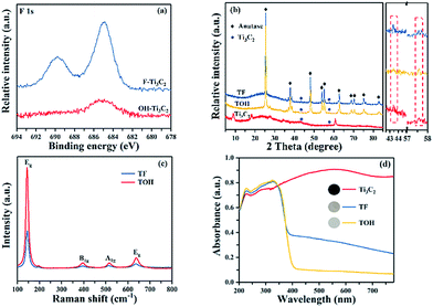
In Fig. 1, the preparation process of MXene Ti3C2/TiO2 composite photocatalysts was divided into two parts. In Part I, different T-terminated (T = F, O, and OH) Ti3C2 specimens were prepared. Firstly, the initial Ti3C2 was prepared by HF-treatment of Ti3AlC2 power,38 and the transformation from Ti3AlC2 into initial Ti3C2 was confirmed through X-ray diffraction (XRD). In Fig. S1a (see the ESI†), the diffraction curves of the (002) and (004) planes of Ti3AlC2 at 9.58° and 19.17° were weaker and shifted toward 8.84° and 18.13°, suggesting the removal of the Al layers and the formation of Ti3C2 after HF treatment.39 Meanwhile, the obtained precipitates possessed abundant functionalities (–F, –OH, and –O). Then, the first route to the treatment of the initial Ti3C2 was washing directly with deionized water three times, and the obtained sample was denoted as F–Ti3C2 (the F–Ti3C2 sample contained –F, –OH and –O functionalities). To highlight the effect of fluorine ions, another route to treat the initial Ti3C2 was chosen to remove fluorine ions. Namely, the obtained initial Ti3C2 was first disposed with NaOH solution and then washed with deionized water, and the product was referred to as OH–Ti3C2 (the OH–Ti3C2 sample still contained –OH and –O functionalities). The crystal structures and chemical compositions of F–Ti3C2 and OH–Ti3C2 were determined through XRD and XPS, respectively. In Fig. S1b (see the ESI†), F–Ti3C2 and OH–Ti3C2 exhibited similar XRD patterns, indicating that the treatment of NaOH solution did not change the crystal structure of Ti3C2. The survey XPS patterns (Fig. S2a in the ESI†) showed the existence of Ti, O, and C. In comparison with F–Ti3C2, an obvious weakness of the F peak could be observed in the high-resolution F 1s XPS spectra of OH–Ti3C2 (Fig. 2a), suggesting that the fluorine ions in OH–Ti3C2 were removed by treatment with NaOH solution. The high-resolution XPS spectra of Ti 2p, C 1s, and O 1s are summarized in Tables S1 and S2 (in the ESI†). The existence of Ti3C2 is demonstrated by various surface compositions (Ti–C, C–Ti–Ox, and so on). These results confirmed that F–Ti3C2 and OH–Ti3C2 were successfully synthesized, and the difference in F–Ti3C2 and OH–Ti3C2 was only fluorine concentration because the treatment of NaOH solution removed fluorine ions without affecting the crystal structure of Ti3C2.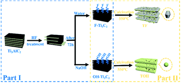 | ||
| Fig. 1 Schematic of the preparation procedure for the synthesis of MXene Ti3C2/TiO2 composite photocatalysts. | ||
In Part II, different MXene Ti3C2/TiO2 composite photocatalysts were prepared. The thermal oxidation method was selected to synthesize MXene Ti3C2/TiO2 composite photocatalysts because it could remove most of the fluorine ions. Namely, F–Ti3C2 and OH–Ti3C2 were calcined at 550 °C for 4 h. After calcination was performed, the obtained samples of F–Ti3C2 and OH–Ti3C2 were labelled TF and TOH, respectively. The crystal structures of TF and TOH were characterized through XRD and Raman patterns. In Fig. 2b, TF and TOH samples exhibit a typical XRD diffraction line of anatase,40 confirming that no rutile and brookite, in addition to anatase, were observed after calcination. Furthermore, a diffraction peak assigned to Ti3C2 could be detected at 43° and 57.5° (see the inset in Fig. 2b), suggesting the generation of TiO2/Ti3C2 hybrids.28 In the Raman patterns of the TF and TOH samples (Fig. 2c), four characteristic peaks located at 144, 400, 415, and 650 cm−1 corresponded to the Eg, B1g, A1g, and Eg modes of the typical anatase phase.
Notably, the diffraction intensity of Eg of TF sample peaks located at 144 and 636 cm−1 was weaker than that of the TOH sample, suggesting the presence of a large number of (001) facets in the TF samples because the number of the symmetric stretching vibration modes of O–Ti–O decreases when the exposed (001) facets exist.41,42 This result indicated that TiO2 with exposed (001) facets can be found in the TF samples. The UV-Vis diffuse reflectance spectroscopy (UV-Vis DRS) spectra were used to further confirm the existence of Ti3C2 and the optical properties of the Ti3C2, TF, and TOH samples. In Fig. 2d, Ti3C2 demonstrated the highest absorption intensity in the full spectrum because of the black feature of Ti3C2. The curves of the TF and TOH samples exhibited a similar trend, which corresponded to the intrinsic properties of anatase TiO2, suggesting the formation of TiO2.43,44 By contrast, the background absorption intensity of TF was higher than that of TOH. This phenomenon should be attributed to the concentration of Ti3C2 in the TF sample, which was higher than that of the TOH sample. This result is easy to understand; generally, the high energy (001) facets is difficult to synthesize. However, TiO2 with exposed (001) facets can be found in the TF samples due to the fluorine reduced the surface energy of (001) facets. Therefore, the transformation of Ti3C2 into TiO2 was prevented because the chemical energy in the system is additionally consumed under the action of fluorine. The result indicated that the concentration of Ti3C2 in the TF sample was higher than that of the TOH sample. These results indicated that the MXene Ti3C2/TiO2 composite photocatalysts were successfully synthesized through a simple calcination method, and the composition of both TF and TOH samples was Ti3C2/TiO2. Moreover, TiO2 exposed (001) facets could be found in the TF samples under the action of fluorine ions.
XPS characterization was conducted to analyse the chemical composition of F–Ti3C2 before and after calcination. In Fig. S2i (see in the ESI†), four elements (Ti, C, O, and F) could be found in the survey curves of TF and F–Ti3C2 samples. Obviously, the diffraction peak of F in the TF samples was considerably weaker than that of the F–Ti3C2 samples, suggesting that fluorine was sharply reduced during calcination. The high resolution Ti 2p curve of the F–Ti3C2 samples is shown in Fig. S2b (see in the ESI†). Six different peaks can be discovered and attributed to the different compositions of Ti.45–48 However, in the high resolution Ti 2p curve of the TF samples (Fig. S2c in the ESI†), only two obvious peaks were found, and they correspond to TiO2 2p1/2 and TiO2 2p3/2.49 This phenomenon indicated the transformation of Ti3C2 into TiO2. The high resolution spectra of C 1s, O 1s, and F 1s are summarized in Tables S1 and S2 (in the ESI†).
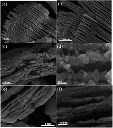
The morphological characteristics of the products before and after calcination treatment can be observed in Fig. 3. In Fig. 3a and b, the Ti3C2 MXene exhibited a multilayer structure after Ti3AlC2 was treated with HF. The thickness of the single layer was approximately 5–15 nm. Interestingly, the TF and TOH samples still maintained a 2D multilayer structure on account of the in situ transformation of the Ti3C2 MXene into TiO2 (Fig. 3c and e). Actually, the structures of the truncated octahedral bipyramid for the TF sample are TiO2 structures, and the layered structures are residual Ti3C2 structures. So uniformly truncated octahedral bipyramidal TiO2 is formed on the surface of Ti3C2 for the TF sample. For the TOH sample, the nanoparticles are TiO2 nanoparticles and layered structures are Ti3C2 structures. This result should be attributed to the fact that fluorine on the surface of the TF sample reduced the surface energy of TiO2, which facilitated the formation of TiO2 with exposed (001) facets.28 For the TOH sample, only sphericity with the lowest surface energy was produced during crystallization due to the absence of fluorine to reduce its surface energy. In addition, the surface area of the TOH sample (41.3 m2 g−1) was larger than that of TF (20.5 m2 g−1). This results also indicated that smaller particles were formed in the surface of TOH than that for TF.
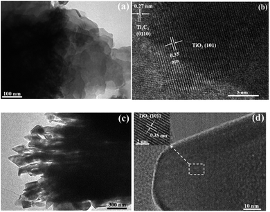
The transmission electron microscopy (TEM) and high-resolution TEM (HRTEM) images of TOH and TF are shown in Fig. 4. The TEM images further confirmed the 2D multilayer structure of the TOH and TF samples (Fig. 4a and c). Clear lattice fringes were found in the TOH and TF samples. In detail, the lattice fringes of 0.35 and 0.27 nm were measured in the TOH sample, and they corresponded to the (101) facets of anatase TiO2 and (0110) facets of Ti3C2 (Fig. 4b),50,51 respectively. The truncated octahedron bipyramid of TiO2 can be clearly observed in the TF samples, and the lattice fringe of the bevel in the truncated octahedral bipyramid was measured to be 0.35 nm, which was assigned to the (001) plane of TiO2. However, the lattice fringe of the top surface in the truncated octahedral bipyramid could not be detected because TOB-T was too long for the electron beam to penetrate. These results suggested that the Ti3C2/TiO2 hybrids were successfully synthesized in TOH and TF samples. By contrast, TOB-T was formed on the surface of the TF sample under the influence of fluorine ions, and nanoparticles were found on the surface of the TOH sample. The percentage of the exposed (001) facets of the TF sample was calculated to be 11% based on the area ratio of the inclined plane to the top surface.
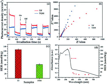
Photocurrent and electrochemical impedance spectra (EIS) were obtained to further investigate the separation and migration of the photogenerated carriers. The photocurrent of pure TiO2 without a co-catalyst was hardly detected because of the rapid recombination of photogenerated carriers. In Fig. 5a, upon light irradiation, a remarkable photocurrent was produced in the TF and TOH samples because of the existence of Ti3C2. Furthermore, the stronger photocurrent in the TF samples than that in the TOH samples was attributed to its (001)–(101) surface heterojunction. The EIS of TF and TOH is shown in Fig. 5b. The impedance of the TF samples was lower than that of the TOH samples, indicating the low charge transfer resistance of the TF samples. These results confirmed that the process of charge transfer and the increase in the separation and migration of the photogenerated carriers should be attributed to the surface heterojunction of (001)–(101) facets and the electron reservoir feature of Ti3C2.
Photocatalytic hydrogen production was performed in glycerinum/water (1![[thin space (1/6-em)]](https://www.rsc.org/images/entities/char_2009.gif) :
:![[thin space (1/6-em)]](https://www.rsc.org/images/entities/char_2009.gif) 10 vol%) solution under light irradiation to conclude the photocatalytic performance of TF and TOH samples. In Fig. 5c, a remarkable hydrogen evolution rate (HER) of the TF and TOH samples could be obtained because of the existence of the co-catalyst Ti3C2. The HER of the TF samples was considerably higher than that of the TOH samples by a factor of 2, suggesting that the exposed (001) facets are key factors for the improvement of the photocatalytic activity of the TF samples. A wavelength-dependent HER of the TF samples was determined using a monochromatic light source. In Fig. 5d, the wavelength-dependent HER increased as the energy of monochromatic light in the excitation region increased. This result indicated that the HER is mainly controlled by light-induced electrons in the TF samples and was in line with the DRS spectrum. Simultaneously, the TF samples exhibited the highest HER with an apparent quantum efficiency of 0.9% under 365 nm monochromatic light irradiation.
10 vol%) solution under light irradiation to conclude the photocatalytic performance of TF and TOH samples. In Fig. 5c, a remarkable hydrogen evolution rate (HER) of the TF and TOH samples could be obtained because of the existence of the co-catalyst Ti3C2. The HER of the TF samples was considerably higher than that of the TOH samples by a factor of 2, suggesting that the exposed (001) facets are key factors for the improvement of the photocatalytic activity of the TF samples. A wavelength-dependent HER of the TF samples was determined using a monochromatic light source. In Fig. 5d, the wavelength-dependent HER increased as the energy of monochromatic light in the excitation region increased. This result indicated that the HER is mainly controlled by light-induced electrons in the TF samples and was in line with the DRS spectrum. Simultaneously, the TF samples exhibited the highest HER with an apparent quantum efficiency of 0.9% under 365 nm monochromatic light irradiation.
Based on the experimental results, Fig. 6 illustrates the tentative mechanism of TiO2/Ti3C2 hybrids for photocatalytic H2 evolution over the TF samples. Under light irradiation, the (001) and (101) facets of TOB-T could be excited to produce photogenerated electrons and holes. The surface band gap of (001) facets is misaligned with that of (101) facets because of the different atomic arrangements on the surface of each facet.52,53 Therefore, the formation of the surface heterojunction between (001) and (101) facets could facilitate the photogenerated electrons to transfer from the (001) to (101) facets because of the staggered band gap. This result led to the accumulation of photogenerated electrons and holes on the (101) and (001) facets, respectively. Moreover, the photogenerated electrons could be transferred from TiO2 to Ti3C2 because of the high conductivity of Ti3C2.54 Namely, Ti3C2, as an electron reservoir in Ti3C2/TiO2 hybrids, captured the photogenerated electrons of (101) facets (see the detail of the bandgap information about the hetero-structure in Fig. S6 in the ESI†).
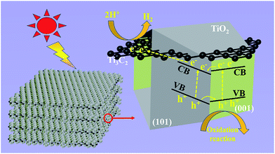 | ||
| Fig. 6 Schematic of the tentative photocatalytic mechanism of truncated octahedral bipyramidal TiO2/Ti3C2 hybrids under light irradiation. | ||
Therefore, an effective separation of the photogenerated carriers was achieved in the Ti3C2/TiO2 hybrids through the transfer of the photogenerated electrons. Therefore, the synergy of the surface heterojunction of (001)–(101) facets and the electron reservoir feature of Ti3C2 could effectively increase the HER of TiO2/Ti3C2 composite photocatalysts.
Conclusions
In summary, binary 2D MXene Ti3C2/TiO2 hybrids were successfully synthesized through a simple calcination of F-terminated Ti3C2. TOB-T with exposed (001) facets could be found because of the effect of fluorine ions. The multilayer structure derived from MXene Ti3C2 is essential for the interaction between TiO2 and Ti3C2. The enhanced HER should be attributed to the (001)–(101) surface heterojunction in the TF samples, in addition to the electron reservoir feature of Ti3C2. A tentative mechanism was proposed based on the experimental results. This work provided a new strategy for the application of 2D MXene materials.Experiment
Materials
Hydrofluoric acid (40 wt%), Ti3AlC2, and NaOH were of analytical grade and used without further purification. Deionized water was used in all the experiments.Sample preparation
Ti3C2 was synthesized in accordance with previous studies.29 In brief, 40 mL of hydrofluoric acid (40 wt%) was gradually dropped to disperse 2 g of Ti3AlC2 powder. The resultant suspension was stirred at normal temperature for 72 h to etch an Al layer. The obtained precipitates were divided into two parts. One part was washed directly with deionized water thrice, and the other part was first disposed with NaOH solution (0.1 mol L−1) and then washed with deionized water. Finally, the precipitates were dried at 80 °C in an oven. The product was referred to as F–Ti3C2 for the former part and OH–Ti3C2 for the latter. A TiO2/Ti3C2 hybrid was prepared through primitive calcination. In brief, 0.3 g of F–Ti3C2 (OH–Ti3C2) was calcined at 550 °C for 4 h in air. The prepared samples were labeled TF (TOH), milled into powder, and collected.Characterization
The XRD patterns were recorded on a D8-Advance diffractometer (Bruker, German) with Ni-filtered Cu Kα radiation at a scan rate (2θ) of 10° min−1, an accelerating voltage of 40 kV, and a current of 40 mA. The TEM images were obtained using a Hitachi H-7650 (HITACHI, Japan) transmission electron microscope at an accelerating voltage of 200 kV, and HRTEM analysis was performed on a JEM-2100F (JEOL, Japan) microscope. The SEM images were obtained on an S-4800 (HITACHI, Japan). The UV-Vis DRS spectra were obtained using a UV-Vis spectrophotometer (Lambda 650s), and Teflon was used as the reflectance standard. The XPS patterns were obtained on a Leybold Heraeus-Shenyang SKL-12 X-ray photoelectron spectrometer, and Mg Kα served as an excitation source. Raman spectra were obtained on a micro-Raman spectrometer (LabRAM HR Evolution) at room temperature under ambient conditions, and the excitation source was a 532 nm Ar+ laser.Photocatalytic H2 production activity
The photocatalytic H2 production of the obtained photocatalysts was measured in a 100 mL three-necked flask at atmospheric pressure and room temperature. A 350 W Xe arc lamp was utilized as a light source and the sacrificial agent was 10% of glycerinum aqueous solution in volume. The detailed steps were as follows: 50 mg of samples was dispersed in 80 mL of sacrificial agent. The suspension solution mixture of photocatalysts was degassed using N2 for 30 min to evict the remaining oxygen and air in the flask. After 1 h of illumination, 0.4 mL of gas was extracted and detected on a gas chromatograph (GC-2004C, Japan).The wavelength-dependent HER of TF samples was determined by a similar method to the photocatalytic H2 production, expect that the light source was replaced by a LED equipped with different monochromatic light. The irradiation intensity of the monochromatic light was about 80 mW cm−2 by controlling internal power of monochromatic light. The QE was determined by using the nether equation:
Photoelectrochemical measurements
Photocurrent and EIS were obtained on a CHI660E (Shanghai Chenhua Limited, China) electrochemical analyzer, which was a three-electrode system that used Pt wire and Ag/AgCl as counter and reference electrodes, respectively. The working electrodes were glass electrodes with an effective area of ca. 1.2 cm2. A 350 W Xe arc lamp and 0.5 M Na2SO4 aqueous solution were used as a light source and an electrolyte, respectively.The glass working electrode was synthesized as follows: a mixture of 0.03 g of the sample, 0.03 g of polyethyleneglycol, and 0.5 mL of ethanol were ground into a slurry. A doctor blade method was used to evenly coat the slurry onto a 2 cm × 1.2 cm F-doped SnO2-coated glass electrode. Finally, the obtained glass electrodes were dried at 100 °C for 60 min in an oven.
Conflicts of interest
There are no conflicts to declare.Acknowledgements
This work was partially supported by the National Natural Science Foundation of China under Grant No. 51672099, 21403079, 61831012 and 51572042, Fundamental Research Funds for the Central Universities under No. 2017-QR-25, Sichuan Science and Technology Program under No. 2019JDRC0027, Science Challenge Project under Grant No. TZ2018003, and International Science & Technology Cooperation Program under Grant No. 2015DFR50870.Notes and references
- L. Cheng, Q. J. Xiang, Y. L. Liao and H. W. Zhang, Energy Environ. Sci., 2018, 11, 1362–1391 RSC.
- F. Y. Cheng, H. Yin and Q. J. Xiang, Appl. Surf. Sci., 2017, 391, 432–439 CrossRef CAS.
- Q. J. Xiang, F. Y. Cheng and D. Lang, ChemSusChem, 2016, 9, 996–1002 CrossRef CAS PubMed.
- J. W. Fu, Q. L. Xu, J. X. Low, C. J. Jiang and J. G. Yu, Appl. Catal., B, 2019, 243, 556–565 CrossRef CAS.
- K. He, J. Xie, M. Li and X. Li, Appl. Surf. Sci., 2018, 430, 208–217 CrossRef CAS.
- A. Fujishima and K. Honda, Nature, 1972, 238, 37–38 CrossRef CAS PubMed.
- C. Athanasekou, G. E. Romanos, S. K. Papageorgiou, G. K. Manolis, F. Katsaros and P. Falaras, Chem. Eng. J., 2017, 318, 171–180 CrossRef CAS.
- X. F. Wang, T. Y. Li, R. Yu, H. G. Yu and J. G. Yu, J. Mater. Chem. A, 2016, 4, 8682–8689 RSC.
- Z. Wang and X. J. Lang, Appl. Catal., B, 2018, 224, 404–409 CrossRef CAS.
- T. D. Pham and B. K. Lee, J. Catal., 2017, 345, 87–95 CrossRef CAS.
- M. S. Akple, J. Low, S. W. Liu, B. Cheng, J. G. Yu and W. K. Ho, J. CO2 Util., 2016, 16, 442–449 CrossRef CAS.
- P. N. Paulino, V. M. M. Salim and N. S. Resende, Appl. Catal., B, 2016, 185, 362–370 CrossRef CAS.
- D. Zhang, X. Ma, H. Zhang, Y. Liao and Q. J. Xiang, Mater. Today Energy, 2018, 10, 132–140 CrossRef.
- Y. Xu, Y. G. Li, P. Wang, X. F. Wang and H. G. Yu, Appl. Surf. Sci., 2018, 430, 176–183 CrossRef CAS.
- X. Zhang, Y. J. Chen, Y. T. Xiao, W. Zhou, G. H. Tian and H. G. Fu, Nanoscale, 2018, 10, 4041–4050 RSC.
- D. Lang, F. Y. Cheng and Q. J. Xiang, Catal. Sci. Technol., 2016, 6, 6207–6216 RSC.
- F. Chen, W. Luo, Y. P. Mo, H. G. Yu and B. Cheng, Appl. Surf. Sci., 2018, 430, 448–456 CrossRef CAS.
- M. Wu, J. Zhang, C. X. Liu, Y. S. Gong, R. Wang and B. B. He, ChemCatChem, 2018, 14, 3069–3077 CrossRef.
- D. Lang, T. Shen and Q. J. Xiang, ChemCatChem, 2015, 7, 943–951 CrossRef CAS.
- P. Wang, Y. G. Lu, X. F. Wang and H. G. Yu, Appl. Surf. Sci., 2017, 391, 259–266 CrossRef CAS.
- D. N. Zhang, X. Y. Ma, H. W. Zhang, Y. L. Liao and Q. J. Xiang, Mater. Today Energy, 2018, 10, 132–140 CrossRef.
- T. Song, P. Y. Zhang, T. T. Wang, A. Ali and H. P. Zeng, Nanoscale, 2018, 10, 2275–2284 RSC.
- W. Chen, Y. H. Wang, S. liu, L. Gao, L. Q. Mao, Z. Y. Fan, W. F. Shangguan and Z. Jiang, Appl. Surf. Sci., 2018, 445, 527–534 CrossRef CAS.
- M. Terracciano, V. Galstyan, L. Rea, M. Casalino, L. D. Stefauo and B. Sbervegleri, Appl. Surf. Sci., 2017, 419, 235–240 CrossRef CAS.
- Y. Y. Duan, L. Liang, K. L. Lv, Q. Li and M. Li, Appl. Surf. Sci., 2018, 456, 817–826 CrossRef CAS.
- Y. Hernandez, V. Nicolosi, M. Lotya, F. M. Blighe, Z. Y. Sun, S. De, I. T. McGovern, B. Holland, M. Byrne, Y. K. Gun'Ko, J. J. Boland, P. Niraj, G. Duesberg, S. Krishnamurthy, R. Goodhue, J. Hutchison, V. Scardaci, A. C. Ferrari and J. N. Coleman, Nat. Nanotechnol., 2008, 3, 563–568 CrossRef CAS PubMed.
- M. Naguib, M. Kurtoglu, V. Presser, J. Lu, J. J. Niu, M. Heon, L. Hultman, Y. Gogotsi and M. W. Barsoum, Adv. Mater., 2011, 23, 4248–4253 CrossRef CAS PubMed.
- Y. J. Li, X. T. Deng, J. Tian, Z. Q. Liang and H. Z. Cui, Appl. Mater. Today, 2018, 13, 217–227 CrossRef.
- G. R. Berdiyorov and K. A. Mahmoud, Appl. Surf. Sci., 2017, 416, 725–730 CrossRef CAS.
- M. Naguib, V. N. Mochalin, M. W. Barsoum and Y. Gogotsi, Adv. Mater., 2014, 26, 992–1005 CrossRef CAS PubMed.
- M. Naguib, O. Mashtalir, J. Carle, V. Presser, J. Lu, L. Hultman, Y. Gogotsi and M. W. Barsoum, ACS Nano, 2012, 6, 1322–1331 CrossRef CAS PubMed.
- C. Peng, X. F. Yang, Y. H. Li, H. Yu, H. J. Wang and F. Peng, ACS Appl. Mater. Interfaces, 2016, 8, 6051–6060 CrossRef CAS PubMed.
- Y. J. Li, Z. H. Yin, G. R. Ji, Z. Q. Liang, Y. J. Xue, Y. C. Guo, J. Tian, X. Z. Wang and H. Z. Cui, Appl. Catal., B, 2019, 246, 12–20 CrossRef CAS.
- Y. J. Li, X. T. Deng, J. Tian, Z. Q. Liang and H. Z. Cui, Appl. Mater. Today, 2018, 13, 217–227 CrossRef.
- T. Cai, L. L. Wang, Y. T. Liu, S. Q. Zhang, W. Y. Dong, H. Chen, X. Y. Yi, J. L. Yuan, X. N. Xia, C. B. Liu and S. L. Luo, Appl. Catal., B, 2018, 239, 545–554 CrossRef CAS.
- J. R. Ran, G. P. Gao, F. T. Li, T. Y. Ma, A. J. Du and S. Z. Qiao, Nat. Commun., 2017, 8, 13907 CrossRef CAS PubMed.
- H. G. Yang, C. H. Sun, S. Z. Qiao, J. Zou, G. Liu, S. C. Smith, H. M. Cheng and G. Q. Lu, Nature, 2008, 453, 638–642 CrossRef CAS PubMed.
- C. Y. Xing, S. Y. Chen, X. Liang, Q. Liu, M. M. Qu, Q. S. Zou, J. H. Li, H. Tan, L. P. Liu, D. Y. Fan and H. Zhang, ACS Appl. Mater. Interfaces, 2018, 33, 27631–27643 CrossRef PubMed.
- S. W. Cao, B. J. Shen, T. Tong, J. W. Fu and J. G. Yu, Adv. Funct. Mater., 2018, 28, 1800136 CrossRef.
- Q. J. Xiang, K. L. Lv and J. G. Yu, Appl. Catal., B, 2010, 96, 557–564 CrossRef CAS.
- B. Li, Z. Zhao, Q. Zhou, B. Meng, X. Meng and J. Qiu, Chem.–Eur. J., 2014, 20, 14763–14770 CrossRef CAS PubMed.
- F. Tian, Y. P. Zhang, J. Zhang and C. X. Pan, J. Phys. Chem. C, 2012, 116, 7515–7519 CrossRef CAS.
- X. Y. Ma, Q. J. Xiang, Y. L. Liao, T. L. Wen and H. W. Zhang, Appl. Surf. Sci., 2018, 457, 846–855 CrossRef CAS.
- Y. Xia, Q. Li, K. L. Lv and M. Li, Appl. Surf. Sci., 2017, 398, 81–88 CrossRef CAS.
- J. Halim, K. M. Cook, M. Naguib, P. Eklund, Y. Gogotsi, J. Rosen and M. W. Barsoum, Appl. Surf. Sci., 2016, 362, 406–417 CrossRef CAS.
- V. Schier, H. J. Michel and J. Halbritter, Fresenius J. Anal. Chem., 1993, 346, 227–232 CrossRef CAS.
- T. Sultana, G. L. Georgiev, G. Auner, G. Newaz, H. J. Herfurth and R. Patwa, Appl. Surf. Sci., 2008, 255, 2569–2573 CrossRef CAS.
- S. A. Shah, T. Habib, H. Gao, P. Gao, W. Sun, M. J. Green and M. Radovic, Chem. Commun., 2017, 53, 400–403 RSC.
- Y. Li, X. H. Feng, Z. X. Lu, H. Yin, F. Liu and Q. J. Xiang, J. Colloid Interface Sci., 2018, 513, 866–876 CrossRef CAS PubMed.
- J. X. Low, L. Y. Zhang, T. Tong, B. J. Shen and J. G. Yu, J. Catal., 2018, 361, 255–266 CrossRef CAS.
- H. Ghassemi, W. Harlow, O. Mashtalir, M. Beidaghi, M. R. Lukatskaya, Y. Gogotsi and M. L. Taheri, J. Mater. Chem. A, 2014, 2, 14339–14343 RSC.
- N. Liu, Y. Chang, Y. L. Feng, Y. Cheng, X. J. Sun, H. Jian, Y. Q. Feng, X. Li and H. Y. Zhang, ACS Appl. Mater. Interfaces, 2017, 9, 5907–5915 CrossRef CAS PubMed.
- A. Y. Meng, J. Zhang, D. F. Xu, B. Cheng and J. G. Yu, Appl. Catal., B, 2016, 198, 286–294 CrossRef CAS.
- C. Peng, P. Wei, X. Li, Y. Liu, Y. Cao, H. Wang, H. Yu, F. Peng, L. Zhang, B. Zhang and K. Lv, Nano energy, 2018, 53, 97–107 CrossRef CAS.
Footnote |
| † Electronic supplementary information (ESI) available. See DOI: 10.1039/c9na00023b |
| This journal is © The Royal Society of Chemistry 2019 |

