
Dipole effects in the photoelectron angular distributions of the sulfur monoxide anion
Beverly
Ru
 a,
C. Annie
Hart
b,
Richard
Mabbs
b,
Samer
Gozem
c,
Anna I.
Krylov
d and
Andrei
Sanov
*a
a,
C. Annie
Hart
b,
Richard
Mabbs
b,
Samer
Gozem
c,
Anna I.
Krylov
d and
Andrei
Sanov
*a
aDepartment of Chemistry and Biochemistry, University of Arizona, Tucson, AZ 85721, USA. E-mail: sanov@arizona.edu
bDepartment of Chemistry, Washington University, Saint Louis, MO 63130, USA
cDepartment of Chemistry, Georgia State University, Atlanta, GA 30302, USA
dDepartment of Chemistry, University of Southern California, Los Angeles, CA 90089, USA
First published on 6th September 2022
Abstract
Photoelectron angular distributions (PADs) in SO− photodetachment using linearly polarized 355 nm (3.49 eV), 532 nm (2.33 eV), and 611 nm (2.03 eV) light were investigated via photoelectron imaging spectroscopy. The measurements at 532 and 611 nm access the X3Σ− and a1Δ electronic states of SO, whereas the measurements at 355 nm also access the b1Σ+ state. In aggregate, the photoelectron anisotropy parameter values follow the general trend with respect to electron kinetic energy (eKE) expected for π*-orbital photodetachment. The trend is similar to O2−, but the minimum of the SO− curve is shifted to smaller eKE. This shift is mainly attributed to the exit-channel interactions of the departing electron with the dipole moment of the neutral SO core, rather than the differing shapes of the SO− and O2− molecular orbitals. Of the several ab initio models considered, two approaches yield good agreement with the experiment: one representing the departing electron as a superposition of eigenfunctions of a point dipole-field Hamiltonian, and another describing the outgoing electron in terms of Coulomb waves originating from two separated charge centers, with a partial positive charge on the sulfur and an equal negative charge on the oxygen. These fundamentally related approaches support the conclusion that electron–dipole interactions in the exit channel of SO− photodetachment play an important role in shaping the PADs. While a similar conclusion was previously reached for photodetachment from σ orbitals of CN− (Hart, Lyle, Spellberg, Krylov, Mabbs, J. Phys. Chem. Lett., 2021, 12, 10086–10092), the present work includes the first extension of the dipole-field model to detachment from π* orbitals.
1. Introduction
Photoelectron angular distributions (PADs) are often used to probe the properties of the molecular orbitals from which the electrons are ejected. Unlike neutral-molecule ionization,1 anion photodetachment leaves behind a neutral residue, which interacts relatively weakly with the departing electron. Therefore, exit-channel interactions are often disregarded in the analysis of anion PADs and the measured photoelectron anisotropy parameters (β) are interpreted in terms of the anion/neutral electronic structure.2This approximation has its limits, which are easily breached if the neutral residue possesses a significant dipole moment. The charge–dipole interactions between the departing electron and the remaining neutral molecule are weaker than the Coulomb force in neutral-molecule ionization, but they do affect the cross-sections and (asymptotic) relative phases of the photoelectron (orbital) angular momentum partial waves.3 Since PADs reflect interference between these partial waves, it is not surprising that they too are sensitive to the interactions. Moreover, the non-spherical dipole potential results in mixing of the partial waves propagating in the dipole field.
In discussions of dipole effects, two important limits are usually encountered. 1.625 Debye = 0.6393 a.u. (1 atomic unit ≡ ea0, e is the elementary charge and a0 the Bohr radius)4 is the critical value of the dipole moment necessary to bind an electron in a fixed-dipole field. Molecular rotation increases the dipole binding threshold, and a more realistic limit is generally accepted to be about 2.4 Debye (0.94 a.u.).4 However, the ability to support a dipole-bound state is not a requirement for the PADs to be affected, a fact that is often overlooked when considering detachment from anions.
A recent report examined the role of electron–dipole interactions in CN− photodetachment.5 The theoretical framework developed there applied to σ-orbital photodetachment, but similar effects can be expected for any photodetachment transition that leaves a significantly polar neutral residue. In the present work, we use photoelectron imaging spectroscopy and theoretical modeling to examine the angular distributions in the photodetachment of the sulfur monoxide anion, SO−. The results show that consideration of dipole effects is important for agreement between theory and experiment. Similar to CN−,5 the SO− PADs are not just signatures of the parent detachment orbitals—they also carry fingerprints of the exit-channel interactions between the departing electron and the neutral residue. Although the dipole moments of SO and CN are similar (1.45 and 1.55 Debye, respectively),6–8 the highest-occupied molecular orbitals have different character (π* and σ, respectively), and this work offers the first extension of the previously published formalism5 to non-σ detachment orbitals. It also allows us to compare the SO− PADs to the extensively studied anion of superoxide, O2−,9–12 a benchmark system in which no dipole is present. The comparison aims to establish which of the two factors contributing to the PAD differences plays a more determining role: the distinct shapes of the detachment orbitals or the exit-channel interactions. This work demonstrates that in the SO−vs. O2− case it is the latter.
Although not quite as frequently as di-oxygen, sulfur monoxide has been studied extensively, especially by the astronomy community. It is involved in several photochemical processes in the atmosphere of Io (one of Jupiter's moons), where it is believed to be generated from Pele-type volcanic activity.13–15 In Io's exosphere and the interstellar space, photoionization of SO results in the formation of SO+.16,17 SO has also been detected in the Hale-Bopp comet,18 while in the interstellar media, it is present in Orion A, ρ Ophiuchi, Sagittarius B2, and many others.19–23 In Earth's atmosphere, SO is commonly produced by ultraviolet photolysis of SO2.24–26 It plays a role in oxidizing sulfur dioxide (SO2) and sulfur trioxide (SO3), both components in acid rain and cloud condensation nuclei that contribute to the global sulfur cycle.25,27
There have been several experimental and theoretical studies on the electronic states of SO and SO+,28–30 while Lineberger and coworkers used photoelectron spectroscopy to study SO−.31 They obtained the high-resolution photoelectron spectrum including the SO−(X2Π) → SO(X3Σ−, a1Δ, b1Σ+) photodetachment transitions and determined the adiabatic electron affinity (EA) of SO to be 1.125(5) eV. Here, we revisit these latter transitions focusing on the corresponding PADs.
2. Experimental methods
The experiments were carried out using the negative-ion photoelectron imaging spectrometer described elsewhere.32,33 A CO2 or O2 carrier gas at a backing pressure of ∼1.4 atm was passed over a saturated solution of elemental sulfur dissolved in CS2, kept at room temperature. The 532 nm results presented here were obtained with CO2 carrier gas, while O2 was used in the 355 nm and 611 nm experiments for increased production of the SO− ions. The precursor gas mixture was expanded into a high-vacuum ion-source chamber (base pressure 2 × 10⁻⁷ Torr; operational pressure 2–3 × 10⁻⁵ Torr) through a pulsed supersonic nozzle (General Valve, Inc., Series 9) operated at a 50 Hz (532 and 355 nm) or 20 Hz (611 nm) repetition rate matching that of the laser.The supersonic expansion was intersected by a beam of electrons emitted from a thoria-coated iridium filament (e-Filaments, LLC). The filament was kept at a variable −200 V to −500 V potential and resistively heated by an approximately 5 A current from a floated DC supply. The plasma created by electron bombardment of the neutral precursor gas was cooled in the supersonic expansion. Negative pulses (about −700 to −900 V) applied to an extraction plate positioned downstream from the ionization region were used to separate the negative ions from the cations and neutral species and extract them into the acceleration region of a Wiley–McLaren time-of-flight mass-spectrometer. After passing through a ∼2 m long flight tube, the anions were separated according to their masses. In the detection region of the instrument, kept at a pressure of ∼10−9 Torr, the SO− ion packets were intersected by a pulsed laser beam.
The photodetached electrons were analyzed using a velocity-map imaging (VMI)34 assembly described elsewhere.32 In the present experiments, the three VMI electrodes were kept at –330, 0, and +900 V, respectively, projecting the photodetached electrons in the direction perpendicular to the ion and laser beams. At the end of a 15 cm long electron flight tube, the electrons were post-accelerated into a 40 mm diameter dual microchannel plate detector coupled to a P47 phosphor screen (Burle Inc.). Images from the screen, fiber-optically coupled to an outside window, were captured using a charge-coupled device camera (Roper Scientific, Inc.). Photoelectron images of SO− were taken at 532 and 355 nm using the second and third harmonics, respectively, of a Spectra Physics Lab-130-50 Nd:YAG laser (25 mJ pulse−1 and 5 mJ pulse−1, respectively, ∼6 ns pulse duration). The 611 nm light was generated by the fluorescence of Rhodamine 640 dye in an ND6000 dye laser pumped by Surelite II-20 Nd:YAG (Continuum, Inc.). In all measurements, the (linear) laser polarization direction was set parallel to the imaging detector surface.
3. Experimental results
Photoelectron images of SO− were collected using 611 nm (2.03 eV), 532 (2.33 eV), and 355 nm (3.49 eV) light. The results are shown in Fig. 1. The laser polarization axis is vertical in the plane of all images. The left and right halves of the composite images shown represent the raw and Abel-inverted data, respectively. Reisler and co-workers’ BASEX program35 was used for inverse Abel transformation.36 The spectra for all wavelengths are plotted together with respect to electron binding energy, eBE = hv − eKE, where hv is the energy of the photon and eKE is electron kinetic energy. These spectra are compared to the higher-resolution 351.1 nm (3.531 eV) spectrum obtained by Lineberger and coworkers,31 shown in the same figure in gray. The comparison was used for electronic-vibrational band assignment.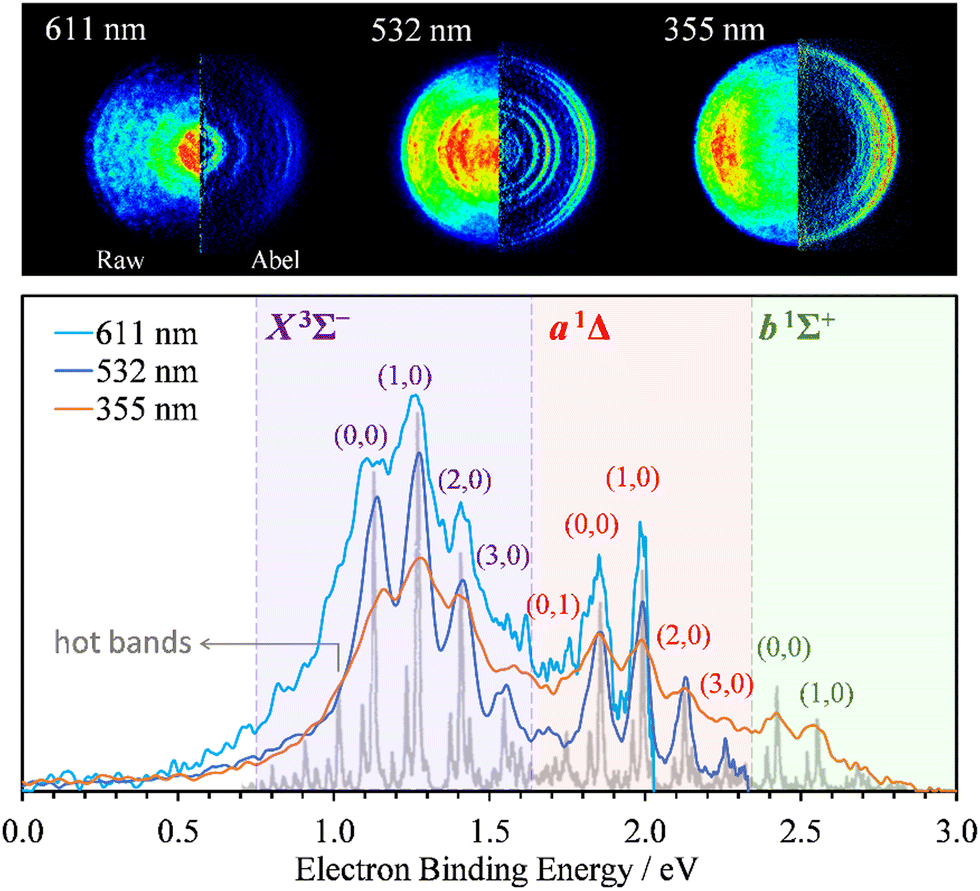 | ||
| Fig. 1 SO− photoelectron images (top) and corresponding spectra (bottom) collected at 611 nm (2.03 eV), 532 nm (2.33 eV), and 355 nm (3.49 eV) using linearly polarized light. The left and right halves of each image shown represent the raw and Abel-inverted data, respectively. The laser polarization direction is vertical in the plane of each image. The light-gray trace superimposed with the present data represents Lineberger's 351.1 nm (3.531 eV) spectrum;31 it is used here to facilitate the vibrational state assignments. The SO(X3Σ−, a1Δ, b1Σ+; v′) ← SO− (X2Π3/2; v′′) photodetachment transitions observed in the spectra are labeled using the (v′,v′′) format. | ||
The X3Σ− and a1Δ electronic states of neutral SO are accessed at 532 and 611 nm, with an additional b1Σ+ state also visible at 355 nm. The vibrational assignments (v′,v′′) for the dominant peaks in the spectra are indicated in Fig. 1 for the SO(X3Σ−, a1Δ, b1Σ+; v′) ← SO− (X2Π3/2; v′′) transitions from the Ω = 3/2 spin-orbit component of the anion electronic state.31
The PADs obtained from the Abel-inverted images were analyzed to determine the anisotropy of each transition. The values of the anisotropy parameter β for each spectral peak were obtained by fitting the standard one-photon PAD function37,38
I(θ) = (σ/4π)[1 + βP2(cos![[thin space (1/6-em)]](https://www.rsc.org/images/entities/char_2009.gif) θ)] θ)] | (1) |
 and β is the anisotropy parameter, whose allowed values range from −1 for a purely perpendicular transition to +2 for a purely parallel transition. The resulting β values are plotted with respect to eKE in Fig. 2(a).
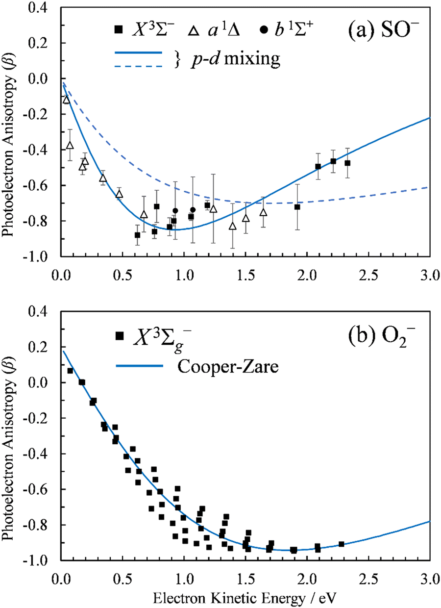 | ||
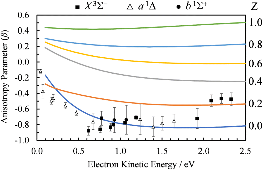
| Fig. 2 Photoelectron anisotropy parameter (β) as a function of eKE for (a) SO− and (b) O2−. The SO− data in (a) correspond to the 611 nm (2.03 eV), 532 nm (2.33 eV), and 355 nm (3.49 nm) experimental results presented in Fig. 1. The blue solid curve in (a) is a 2p–3d mixing curve calculated using eqn (2) with γd = 0.81, A1 = 0.53 eV−1, A2 = 0.10 eV−1, B2 = 11.4 eV−1, and cosδ2,0 = cosδ3,1 = 0.96. The dashed curve corresponds to A1 = 0.35 eV−1, B2 = 1.7 eV−1, with all other parameters unchanged (see the text for details). The curve in (b) is defined by Hanstorp's implementation of the Cooper–Zare equation [or, equivalently, eqn (2) with γd = 1], using A2 = 0.36 eV−1 and cosδ3,1 = 0.96. | ||
4. Modeling and discussion
4.1. SO−versus O2−
The spectral assignments and spectroscopic constants of SO− and the three lowest electronic states of SO have been reported previously.31 In this work, we focus on the information contained in the photoelectron angular distributions. In particular, we highlight the differences between two isovalent anions, SO− and O2−. O2− PADs have been studied in detail previously.9–12 For easy comparison with the present SO− data, Fig. 2(b) displays the anisotropy values for the X3Σg− ← X2Πg transition in O2−, similarly plotted with respect to eKE. The O2−β values were reported previously by Van Duzor et al.12 The reader is referred to Fig. 3 in ref. 12 for vibrational assignments.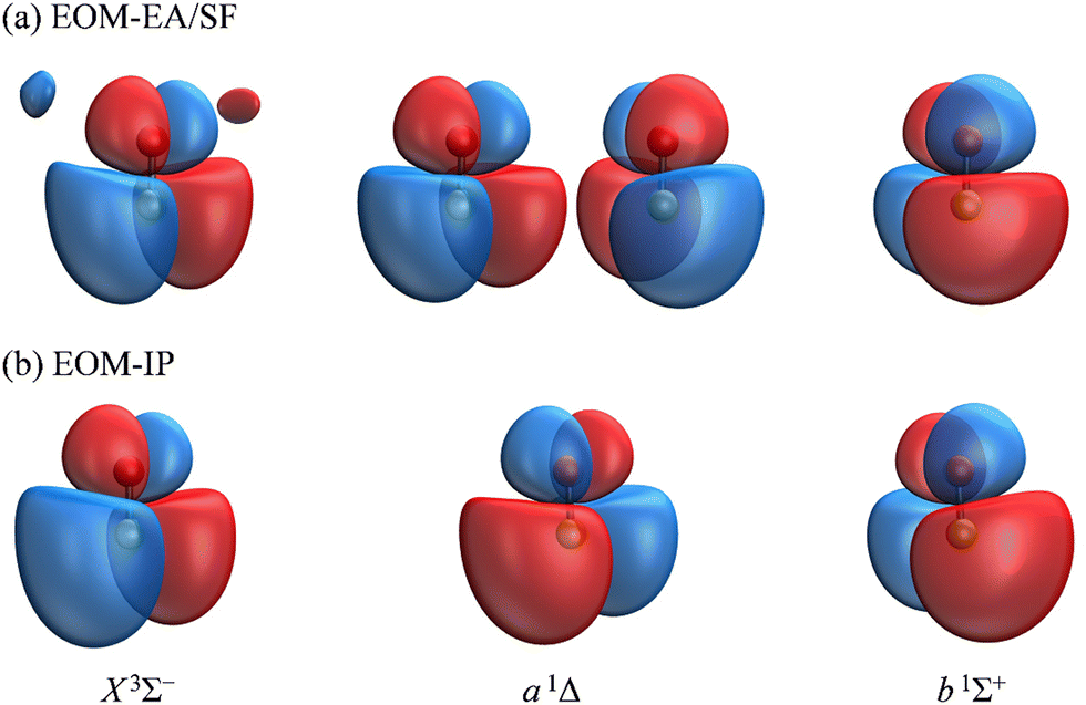 | ||
| Fig. 3 The Dyson orbitals corresponding to detachment transitions from SO− (X2Π) to the X3Σ−, a1Δ, and b1Σ+ electronic states of neutral SO. The orbitals shown in (a) were calculated using transitions from EOM-EA-CCSD to EOM-SF-CCSD states, each starting from the common triplet-state reference, […]22(πα)1(π′α′)1, where π and π′ are the canonical HOMOs of SO(X3Σ−) and […]22 is the closed-shell configuration comprised of 22 electrons. The orbitals in (b) were obtained using EOM-IP-CCSD, starting from the […]22(πα)1(πβ)1(π′α)1 anion reference. The two orbitals for the a 1Δ state shown in (a) describe the degenerate […]22(πα)1(πβ)1(π′α)1 → […]22(πα)1(πβ)1 and […]22(πα)1(π′α)1(π′β)1 → […]22(π′α)1(π′β)1 transitions accessible from the triplet reference. Only the former is accessible from the anion reference and hence only one a 1Δ orbital in shown in (b). The calculations were done using the aug-cc-pVTZ+5s5p5d5f basis set at the CCSD(T)/aug-cc-pVTZ optimized geometry of the anion. Isosurface values 0.02. | ||
O2−: the Cooper–Zare central-potential model
Historically, a common approach to modeling one-photon PADs has been based on the Cooper–Zare central-potential model, which assumes that the detachment Dyson orbital or the initial (bound) state of the electron can be described by a definite value of the orbital angular momentum quantum number l. In this case, the final state of the electron is a superposition of the dipole-allowed partial waves with the orbital angular momentum quantum number![[small script l]](https://www.rsc.org/images/entities/char_e146.gif) = l ± 1. The photoelectron anisotropy resulting from interference of these waves is described by the Cooper–Zare formula,38,39 which is based on the original derivation by Bethe.40,41 Direct application of the Cooper–Zare model requires the calculation of energy-dependent transition-dipole matrix elements for the partial waves,42 but a popular simplification, first introduced by Hanstorp et al.,43 allows to forego this direct calculation. Hanstorp's approximation assumes that the ratio of the l ± 1 partial cross-sections (σl±1) scales with energy in accordance with the Wigner law:3σl+1/σl−1 ∝ εl+3/2/εl−1/2, i.e., σl+1/σl−1 = Al2ε2, where ε ≡ eKE and Al is the Hanstorp coefficient.
= l ± 1. The photoelectron anisotropy resulting from interference of these waves is described by the Cooper–Zare formula,38,39 which is based on the original derivation by Bethe.40,41 Direct application of the Cooper–Zare model requires the calculation of energy-dependent transition-dipole matrix elements for the partial waves,42 but a popular simplification, first introduced by Hanstorp et al.,43 allows to forego this direct calculation. Hanstorp's approximation assumes that the ratio of the l ± 1 partial cross-sections (σl±1) scales with energy in accordance with the Wigner law:3σl+1/σl−1 ∝ εl+3/2/εl−1/2, i.e., σl+1/σl−1 = Al2ε2, where ε ≡ eKE and Al is the Hanstorp coefficient.
The Cooper–Zare formula is strictly applicable to atomic transitions, but similar approaches taking rotational motion into account have been developed for diatomics.44,45 In the absence of resolved rotational structure, the original Cooper–Zare formula has been used to describe photodetachment of molecular anions, including O2− and S2−.10–12,46 These applications rely on the approximate description of the detachment orbitals in these diatomics using a single atomic-like function with l = 2.2 To this end, Fig. 2(b) includes a model curve calculated using Hanstorp's implementation of the Cooper–Zare equation with A2 = 0.36 eV−1 and cosδ3,1 = 0.96, where δ3,1 is the assumed phase shift between the = 1 and 3 partial waves of the emitted electron. These parameter values are consistent with the detailed (vibrational state specific) findings of Van Duzor et al.,12 as well as with a similar analysis (disregarding the vibronic effects) by Blackstone et al.47 For purposes of comparison with SO−, we will use the Cooper–Zare curve shown in Fig. 2(b) to describe the overall β(ε) trend in O2− experimental data.12
SO−: the p–d mixing model
The number of molecular systems for which the above approach with a single l value may work is limited. As a case in point, it cannot be applied directly to SO− because of the asymmetric (lopsided) character of the π* HOMO (highest occupied molecular orbital) or, more precisely, the Dyson orbitals corresponding to the three lowest photodetachment transitions. To overcome the central-potential limitation, various l-mixing models have been developed in recent years.48 These models approximate the detachment orbitals as superpositions of two (or more) atomic-like functions with different l values, all placed on the same center in the molecular frame. The s–p mixing approach is useful for hybrid orbitals in organics2,49–51 and polarization interactions of s-type anions in clusters.52,53 Of particular relevance to the present work is the p–d variant48 of l-mixing. Unlike the HOMO of O2−, the essential character of the lopsided π* HOMO of SO− cannot be captured by a single l = 2 function; it requires at least one additional component with l = 1. Similar scenarios have been discussed previously for NO− or HO2−.47
In detachment from a mixed-character orbital described as  where γd is the fractional d-character (0 ≤ γd ≤ 1), β(ε) is given by:47,48
 | (2) |
While l-mixing provides insight into the PADs, its downside is the number of required model parameters, which increases with increasing number of the l components included. For reference, the Hanstorp formulation of the Cooper–Zare equation for detachment from any orbital with l > 0 includes one Hanstorp coefficient (Al) and one phase shift (δl+1,l−1). In comparison, the p–d variant of the mixing model, eqn (2), involves the fractional d character of the orbital (γd), three generalized Hanstorp coefficients (A1, A2, and B2), and two relative phases (δ2,0 and δ3,1).47,48 The Hanstorp coefficients are not entirely independent of each other: treating the radial parts of the p and d components of the MO as hydrogenic functions, A1, A2, and B2 can be expressed in terms of two effective charges, ζ2p and ζ3d, describing the p and d contributions to the MO.47,48A1 is defined by ζ2p, A2 by ζ3d, while B2—by both ζ2p and ζ3d and can therefore be determined from the two A coefficients. Yet, this still leaves five parameters that need to be determined (γd, ζ2p, ζ3d, δ2,0, and δ3,1 or, equivalently, γd, A1, A2, δ2,0, and δ3,1). While these properties can be, in principle, evaluated by ab initio methods, they are often used as empirical fitting parameters. Unfortunately, such black-box application of the model amounts to fitting experimental data with a many-parameter function: an adequate fit can usually be obtained, but the physical insight is limited.
It is mainly to describe the overall experimental trend for comparison with O2− and with the more robust treatments to follow that we include two different 2p–3d mixing curves in Fig. 2(a), both calculated viaeqn (2). The solid curve, representing the overall experimental trend, was generated with γd = 0.81, A1 = 0.53 eV−1, A2 = 0.10 eV−1, B2 = 11.4 eV−1, and cosδ2,0 = cosδ3,1 = 0.96. The phase-shifts were set equal to the O2− value,12 while the three Hanstorp coefficients are defined by effective charges ζ2p = 1.05 and ζ3d = 3.10 according to the formulae in eqn (6) in ref. 47. The above γd, ζ2p, and ζ3d values match the model to the experimental results, but the curve shown is not a unique fit to the data. The significance of the dashed curve in Fig. 2(a) will be explained later.
Note that A2 = 0.10 eV−1 for SO− [solid curve in Fig. 2(a)] can be compared to A2 = 0.36 eV−1 for O2−. The Hanstorp coefficients are generally associated with the “size” of the detachment orbital. For example, if the d components of the two MOs are each described by a hydrogenic function with effective charge ζ3d, then A2 ∝ 1/ζ3d2.47,48 That is, the larger the A2 value, the smaller the effective charge, and the more diffuse the corresponding MO. Comparing the A2 values for SO− and O2−, the less diffuse nature of SO− is consistent with its larger detachment energy: EA(SO) = 1.125(5) eV vs. EA(O2) = 0.448(6) eV.31,54
While the EA consideration agrees with the observed anisotropy results, the above logical chain nonetheless does not stand up to scrutiny. That is because, as we will show shortly, no ab initio treatment of SO− PADs can capture the experimental β(ε) trend unless another property distinguishing SO− from O2− is considered—the dipole moment of the neutral residue.
4.2. Ab initio modeling neglecting electron–dipole interactions
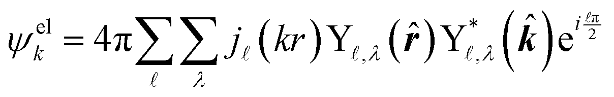
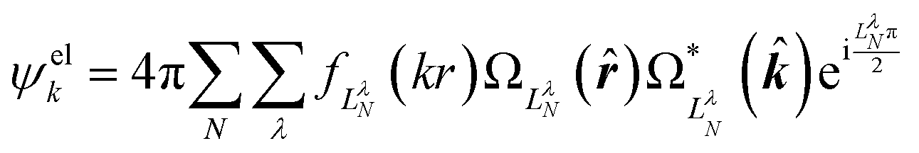
The ab initio calculations of SO− PADs first focus on the detachment orbitals and the final state of the electron, without accounting for its interactions with the dipole moment of the neutral residue. In the following, several increasingly sophisticated approaches applying the free electron approximation fail to yield satisfactory descriptions of the experimental observations, and the importance of including dipole effects is demonstrated. | (3) |
There are several approaches for the treatment of ψelk.57,59–62 We will first attempt to describe the departing electron as a free particle experiencing no interactions with the neutral residue, aiming to show that this approach (commonly used for anion photodetachment) is inadequate in the present case.
 | (4) |
,λ are spherical harmonics and j(kr) are integer-order spherical Bessel functions for a plane wave. In contrast to the l components of the detachment orbital, and λ in eqn (4) describe the emitted waves ( = l ± 1).
To apply this approach to SO−, the anion geometry was optimized with CCSD(T)/aug-cc-pVTZ. The equation-of-motion (EOM-CCSD) method63 was then used to calculate the Dyson orbitals for each of the SO(X3Σ−, a1Δ, b1Σ+) ← SO− (X2Π3/2) transitions at the optimized geometry (R = 1.592 Å) of the anion. Two different EOM approaches were used. In the first, the SO− (X2Π3/2) and SO(X3Σ−, a1Δ, b1Σ+) states were obtained using electron-attachment (EOM-EA-CCSD) and spin-flip (EOM-SF-CCSD) calculations, respectively, starting from the common triplet-state CCSD reference.64,65 This approach uses a well-behaved reference and treats the initial (SO−) and all the final (neutral SO) states on an equal footing.66 The second approach uses ionization-potential (EOM-IP-CCSD) ansatz to access each of the three neutral states starting from the (doublet) anion reference.63 By virtue of using orbitals and coupled-cluster amplitudes optimized for the anion, this approach describes the anion state better than the first one, but can be affected by artifacts due to symmetry breaking of the open-shell doublet reference and an imbalance in treating degenerate π* orbitals.
The aug-cc-pVTZ+5s5p5d5f basis set was used for most ab initio calculations, unless indicated otherwise. The basis set was constructed by supplementing the standard aug-cc-pVTZ basis with five s, five p, five d, and five f additional diffuse functions with exponents decreasing progressively by a factor of 2. All electronic structure calculations were carried out using Q-Chem.67
The Dyson orbitals obtained using the above EOM-EA/SF and EOM-IP approaches are shown in Fig. 3(a) and (b), respectively. Although nominally each of the three transitions removes an electron from the doubly degenerate π* HOMO of SO−, in the spin-unrestricted picture neither the canonical MOs nor Dyson orbitals for the three transitions are identical. As expected, the Dyson orbitals calculated using the EOM-EA/SF and EOM-IP methods are similar in appearance, but this assessment refers only to the orbital shapes at the chosen isosurface amplitude. The corresponding 〈R2〉 values indicate that the EOM-IP orbitals are consistently more diffuse than their EOM-EA/SF counterparts. For the X3Σ− transition, 〈R2〉 = 2.192 and 2.572 Å2 describe the EOM-EA/SF and EOM-IP Dyson orbitals, respectively. The corresponding values for a1Δ are 2.112 vs. 2.426 Å 2, while those for b1Σ+ are 2.049 vs. 2.257 Å2. The 〈R2〉 differences are largely due to the long-range tails of the wave functions, rather than their short-range amplitudes, which is why they are not seen in Fig. 3. To illustrate this point, Fig. 4 shows one-dimensional plots of the y dipole operator (ŷ) multiplied by the EOM-EA/SF and EOM-IP Dyson orbitals for the X3Σ− transition. The graph reveals a more diffuse tail of the orbital computed using EOM-IP.
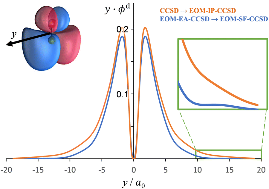 | ||
| Fig. 4 A plot of y⋅ϕd(y) versus ŷ for Dyson orbitals computed for detachment from SO−(X2Π) to the X3Σ− state of SO. The figure shows Dyson orbitals computed using CCSD → EOM-IP-CCSD (orange) and EOM-EA-CCSD → EOM-SF-CCSD (blue) wave functions with the aug-cc-pVTZ+5s5p5d5f basis set. The y axis was chosen for this plot, because it goes through a region of the Dyson orbital that has a large electron density. | ||
From the Dyson orbitals, the ezDyson 5.0 program68 was used to calculate the β(ε) curves using the plane-wave expansion represented by eqn (4) with waves up to = 5 included.59 The results are shown in Fig. 5(a) for the EOM-EA/SF orbitals and Fig. 5(b) for EOM-IP. In each case, the calculated curves are compared to the experimental data reproduced from Fig. 2(a). Unlike the p–d mixing and Cooper–Zare curves in Fig. 2, the ezDyson curves in Fig. 5 are purely ab initio: no parameters were adjusted to match them to the experimental results. Overall, the agreement between either set of the ezDyson curves and the experiment is poor: the models significantly overestimate the location of the β(ε) minima. Also surprising is the fact that there is a significant discrepancy between β(ε) curves computed with EOM-EA/SF and EOM-IP Dyson orbitals.
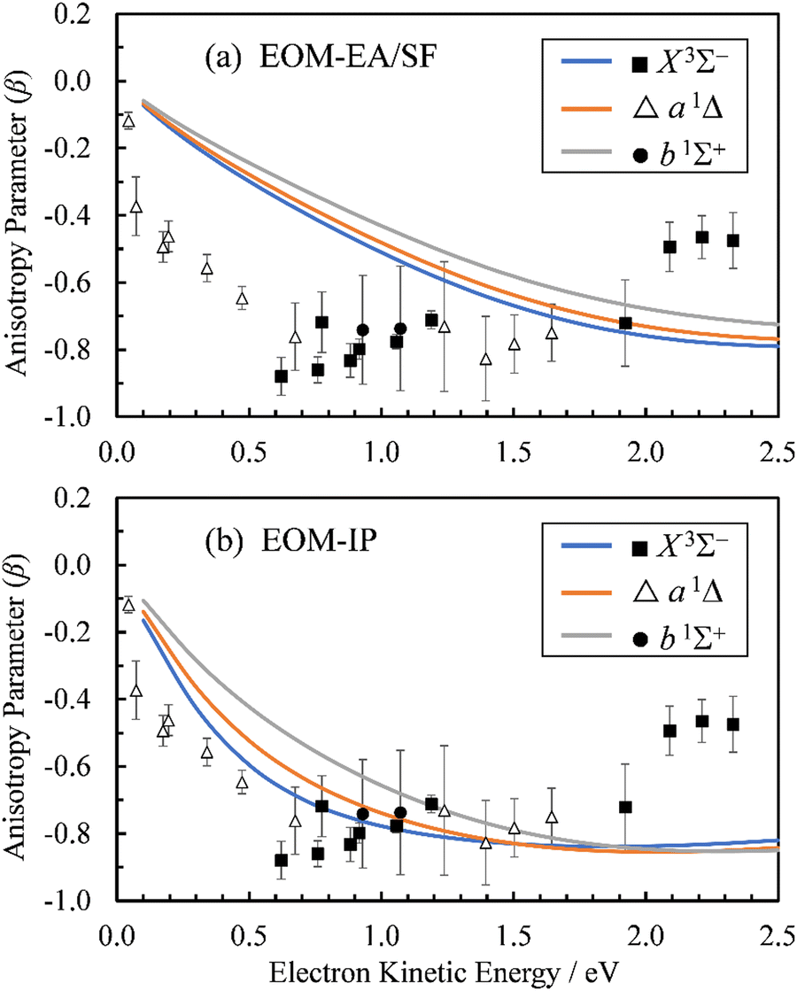 | ||
| Fig. 5 Curves represent β(ε) trends computed for the three neutral states accessed in SO− photodetachment: X3Σ− (blue), a1Δ (orange), and b1Σ+ (grey). The curves in (a) were calculated using the EOM-EA/SF Dyson orbitals shown in Fig. 3(a), whereas the curves in (b)—the EA-IP orbitals from Fig. 3(b). A plane-wave expansion of the emitted-electron wave function was used in each case. Symbols represent the experimental data reproduced from Fig. 2(a) for comparison. | ||
As noted above, the two approaches differ by their treatment of the electron correlation and orbital relaxation effects in anionic and neutral states. Both methods are known to be robust and are comparable in the level of correlation treatment (both include up to double excitations); however, as our results indicate, one may be more effective than the other in treating anionic states. We attribute the discrepancy between the two sets of computed anisotropy trends to the sensitivity of PADs to the diffuse parts of the wave functions. The importance of long-range wave function behavior in PAD calculations has been stressed before;69 it comes from the dipole operator ![[r with combining circumflex]](https://www.rsc.org/images/entities/i_char_0072_0302.gif) , which amplifies the contribution of the tails of Dyson orbitals into the dipole matrix elements.
, which amplifies the contribution of the tails of Dyson orbitals into the dipole matrix elements.
The l-mixing formalism provides an alternative perspective on this effect. The generalized Hanstorp coefficients depend on radial integrals of orbital functions scaled by high powers of r, amplifying the effect of diffuse orbital tails on the resulting PADs.48 If hydrogenic radial functions are used, the B2 coefficient in eqn (2) scales as B2 ∝ ζ73d/ζ92p, where ζ3d and ζ2p are the effective charges introduced in Section 4.1.47,48 While the appearance of the orbitals in Fig. 3 is defined mainly by their dominant d character, a major effect on the β(ε) curve comes from the long-range scaling of the more diffuse (ζ2p < ζ3d) and relatively minor p component of the orbital, described by ζ2p.
To support this point, the dashed curve in Fig. 2(a) was generated using eqn (2) with the same parameters as the solid curve, except for ζ2p, which was increased from 1.05 (solid curve) to 1.30 (dashed curve). This change makes the p (polarization) component less diffuse, without affecting the orbital's dominant d contribution. The resulting change in β(ε), i.e., a significant shift of the minimum to larger eKE, is qualitatively similar to how the EOM-EA/SF ezDyson curves in Fig. 5(a) differ from their EOM-IP counterparts in Fig. 5(b). Therefore, it should come as no surprise that the differences in the long-range behavior of the EOM-EA/SF and EOM-IP Dyson orbitals lead to significant variations in the predicted anisotropy trends. Using the axis definition from Fig. 4, the p component of the p–d model orbital in the l-mixing treatment of SO− is represented specifically by a py function. The above empirical conclusion about the less diffuse nature of the p component describing the EOM-EA/SF orbital, compared to EOM-IP, is therefore consistent with the y-dimension plots in Fig. 4.
The differences between the EOM-EA/SF and EOM-IP approaches are ultimately rooted in approximate treatment of electron correlation. These differences are expected to decrease and eventually disappear when higher excitations are included (triples, quadruples,…), as the two treatments become equivalent at the full configuration interaction limit.
Moreover, there were discrepancies between the predicted ezDyson curves and the experimental trends. Due to the similarity of the β(ε) curves for each of the X3Σ−, a1Δ, and b1Σ+ neutral states, the calculations discussed in the remainder of this section will focus on the X3Σ− state. Unless indicated otherwise, the discussion is focused on the EOM-IP Dyson orbitals computed with the aug-cc-pVTZ+5s5p5d5f basis set.
To check the sensitivity of the calculations to where we place the origin of the plane-wave expansion, we compared β(ε) computed with the expansion placed at the centroid of the Dyson orbital to those computed with the origin of expansion placed at the sulfur atom. As shown in Fig. 6(a), the sulfur-centered calculations resulted in only a small change.
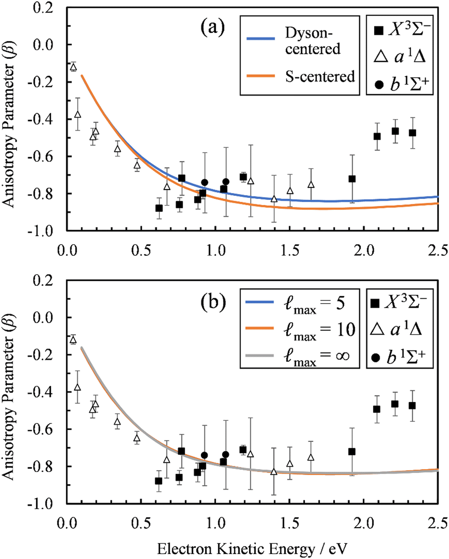 | ||
| Fig. 6 (a) Comparison of the β(ε) profiles for photodetachment into the X3Σ− state of SO using a plane-wave expansion centered on the Dyson orbital centroid (Dyson-centered, blue) and on the sulfur atom (S-centered, orange). (b) Comparison of the β(ε) profiles for photodetachment into the X3Σ− state of SO when truncating the plane wave expansion at max = 5 (blue), 10 (orange), or without using a plane wave expansion with numerical averaging (max = ∞). In both panels, symbols represent the experimental data reproduced from Fig. 2(a) for comparison. Calculations were carried out using EOM-IP-CCSD/aug-cc-pVTZ+5s5p5d5f Dyson orbitals. | ||
Whereas the partial-wave expansion per eqn (4) provides a useful tool to analyze the wave function of the ejected photoelectron for contributions of different angular momentum quantum numbers, in practice it must be truncated at some finite value of . Such a truncation may be justified for molecular orbitals that resemble atomic orbitals, especially at low eKE. Nonetheless, we test the consequences of truncating the partial wave expansion at = 5 in two ways. First, we increased the upper limit of to 10. As shown in Fig. 6(b), this had a negligible effect on the β(ε) curves. Next, we avoid the partial-wave expansion by using the full expression for the plane wave,
 | (5) |
| σpar ∝ 〈ϕdL|rY1,0|eizr〉〈e−izr|rY1,0|ϕdR〉 | (6) |
 | (7) |
 | (8) |
In eqn (6) and (7), ϕdL is the left Dyson orbital and ϕdR is the right Dyson orbital (for Hermitian methods the two are identical).70 Averaging over molecular orientations is performed numerically in ezDyson using orientations computed with REPULSION.71
The results of these calculations are represented by the max= ∞ curve in Fig. 6(b). Again, using the exact expression for the plane wave gave almost identical results as using the partial-wave expansion with max = 10 or 5. In fact, the max = 5 (blue) curve is difficult to discern in Fig. 6(b), because it coincides almost exactly with the other two curves in the figure. This demonstrates that using the partial-wave expansion with terms up to = 5 is sufficient for describing the near-threshold photoelectron anisotropy in SO−.
While the ab initio calculations using plane-wave description of the ejected electron do not agree quantitatively with the experiments, the β(ε) profile has the correct shape; the calculations just overestimate the energy of the β(ε) minimum. The value of β is dependent on the contributions of partial spherical waves with different angular momenta to ψelk. When ψelk is dominated by = 0 waves (near the ionization threshold), β ≈ 0. The mixing in of higher angular momentum spherical partial waves gives rise to cross-terms that result in a negative β.72 As higher angular momentum waves become dominant at higher energies, β increases and becomes positive. The energy where this occurs is determined by the integral 〈ψelk|rY1,0|ϕd〉. The disagreement between the ab initio calculations and experiment, therefore, must be because partial waves with > 0 do not overlap early enough with |rY1,0|ϕd〉 as the energy increases. There are two possible explanations for this:69
(1) The true Dyson orbital is more diffuse than the computed one, and therefore starts overlapping with > 0 waves at lower energies.
(2) The interaction between the photoelectron wave function (ψelk) and the SO molecule after detachment cannot be neglected. That is, a plane wave treatment of ψelk is not adequate and an improved theory is required to account for this interaction.
The first explanation is unlikely, because Dyson orbitals were computed using correlated EOM-CCSD wave functions with the standard triple-ζ basis augmented with 20 additional diffuse functions. To confirm that the basis set is not an issue, we carried out calculations using four different basis sets. Specifically, the aug-cc-pVTZ+5s5p5d5f results were compared with aug-cc-pVTZ, aug-cc-pVQZ, and aug-cc-pVQZ+2s2p1d1f1g basis set calculations. The latter is constructed by supplementing aug-cc-pVQZ with two s, two p, and one of each d, f, and g additional diffuse functions, with the exponents decreasing by a factor of 3. The results (Fig. 7) indicate that, regardless of whether EOM-EA/SF or EOM-IP was used, including diffuse functions in the basis set does have an effect on the β(ε) values. However, once such diffuse functions are added, the calculations are not very sensitive to the details of how many diffuse functions are added. For example, the less diffuse aug-cc-pVQZ+2s2p1d1f1g basis set and the more diffuse aug-cc-pVTZ+5s5p5d5f give essentially the same results.
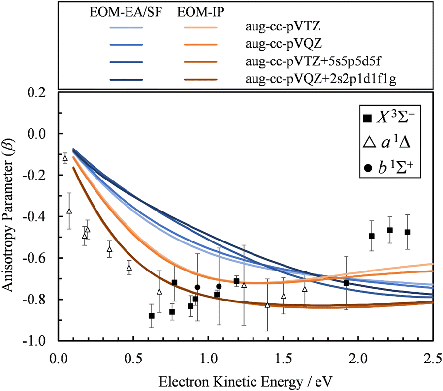 | ||
| Fig. 7 Comparison of the β(ε) profiles for photodetachment into the X3Σ− state of SO obtained using EOM-EA/SF (different shades of blue) and EOM-IP (different shades of orange) Dyson orbitals with different basis sets. Symbols represent the experimental data reproduced from Fig. 2(a) for comparison. | ||
This leaves us with the second hypothesis. While the expansion in eqn (4) is rigorously complete (assuming the upper limit of is set to infinity), it neglects interactions between the outgoing electron and the remaining neutral molecule. Thus, it does not describe the final state of the emitted electron in cases when such interactions cannot be ignored. As SO− appears to be such a case, the way forward is to use final-state basis functions that accommodate exit-channel interactions. At first, we will attempt to use a simple point-charge (Coulomb) interaction-consistent basis set. This approach will fail, similar to plane waves, but further treatments explicitly including the dipole field will succeed. Taken together, these results will provide a clear indication of the importance of specifically electron–dipole interactions in SO− photodetachment.
(kr) in eqn (4) with Coulomb radial functions R(kr,η) that account for an electrostatic interaction: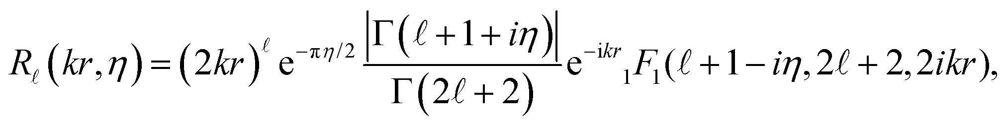 | (9) |
 | (10) |
> 0 becomes large near the ionization threshold, causing the value of β to increase above 0 even at near-threshold energies.
 | ||
| Fig. 8 Comparison of the β(ε) profiles for photodetachment into the X3Σ− state of SO using Dyson-centered Coulomb waves with varying values of the charge parameter Z (indicated to the right of each curve). Symbols represent the experimental data reproduced from Fig. 2(a) for comparison. Calculations were carried out using EOM-IP-CCSD/aug-cc-pVTZ+5s5p5d5f Dyson orbitals. | ||
A problem with using a Coulomb wave expansion of ψelk in combination with the single-center electric-dipole approximation, 〈ψelk|rY1,0|ϕd〉, is that selection rules stemming from orthogonality conditions are lost. By having the center of expansion of ψelk placed at the centroid of the Dyson orbital and therefore, in this case, displaced from the S and O atomic centers, multiple high angular momentum partial waves contribute significantly to the wave expansion even at low energies. In practice, we must truncate the expansion at some finite (in this case, we use = 10). An even more serious issue is that a single-center expansion in terms of Coulomb waves is a monopolar approach which cannot reasonably account for the dipole moment of the neutral residue—a feature that will be shown to be critical in the present case. Both of these limitations are resolved in the second part of Section 4.3.
4.3. Ab initio treatment of the electron–dipole interactions
Replacing the spherical Bessel functions j(kr) in eqn (4) with Coulomb radial functions from eqn (9), as described in Section 4.2, adopts an interaction-consistent basis for the final state of the electron. However, if only a single expansion center is used, this approach does not introduce a dipole moment into the system. We now turn to two alternative formalisms to model the exit-channel interactions between the emitted electron and the polar neutral residue.
 | (11) |
 Their indices LλN are determined from the eigenvalues of the point-dipole matrix
 | (12) |
 , ( + 1), are defined by the quantum number, which is always integer, the similarly expressed eigenvalues of the composite operator
  are defined by eigenvalues LλN(LλN + 1), where LλN is non-integer, if D ≠ 0. The corresponding eigenfunctions,
  , replace the standard spherical harmonics of eqn (4). The non-integer LλN values reflect the mixing of the pure angular momentum components of the free electron due to interactions with the point dipole. The corresponding angular functions can therefore be described as superpositions of pure spherical harmonics:
 | (13) |
 are the eigenvector coefficients from the point dipole matrix in eqn (12). Unlike the magnitude of orbital angular momentum, its projection onto the dipole axis (represented by the quantum number λ) is still a conserved quantity. In the limit of zero dipole moment, the free-particle and point-dipole approaches become identical and LλN correlates with a particular , λ combination. Thus, the index N can be correlated with a zero-dipole-limit
 ![[small script l]](https://www.rsc.org/images/entities/i_char_e146.gif) quantum number.
quantum number.
Although still approximate, the point-dipole approach gives a strong indication of the importance of electron–dipole interactions in photodetachment.5 To illustrate this point, Fig. 9 shows isosurface representations of the continuum probability densities at D = 0 (left) and D ≠ 0 (right) for particular  . For D = 0, the probability densities are those of a single spherical harmonic (multiplied by the appropriate radial function). For D = 0.60 a.u. (1.53 Debye), there are small quantitative differences to the D = 0 case for larger N, λ, but they are not visually obvious and hence omitted from the figure. That these differences are small is mainly an effect of the centrifugal barrier, which suppresses the radial amplitude and, hence, point-dipole functions correlating to higher in the vicinity of the dipole. However, even by eye, the point-dipole functions correlating to smaller (N ≤ 2) are strongly affected.
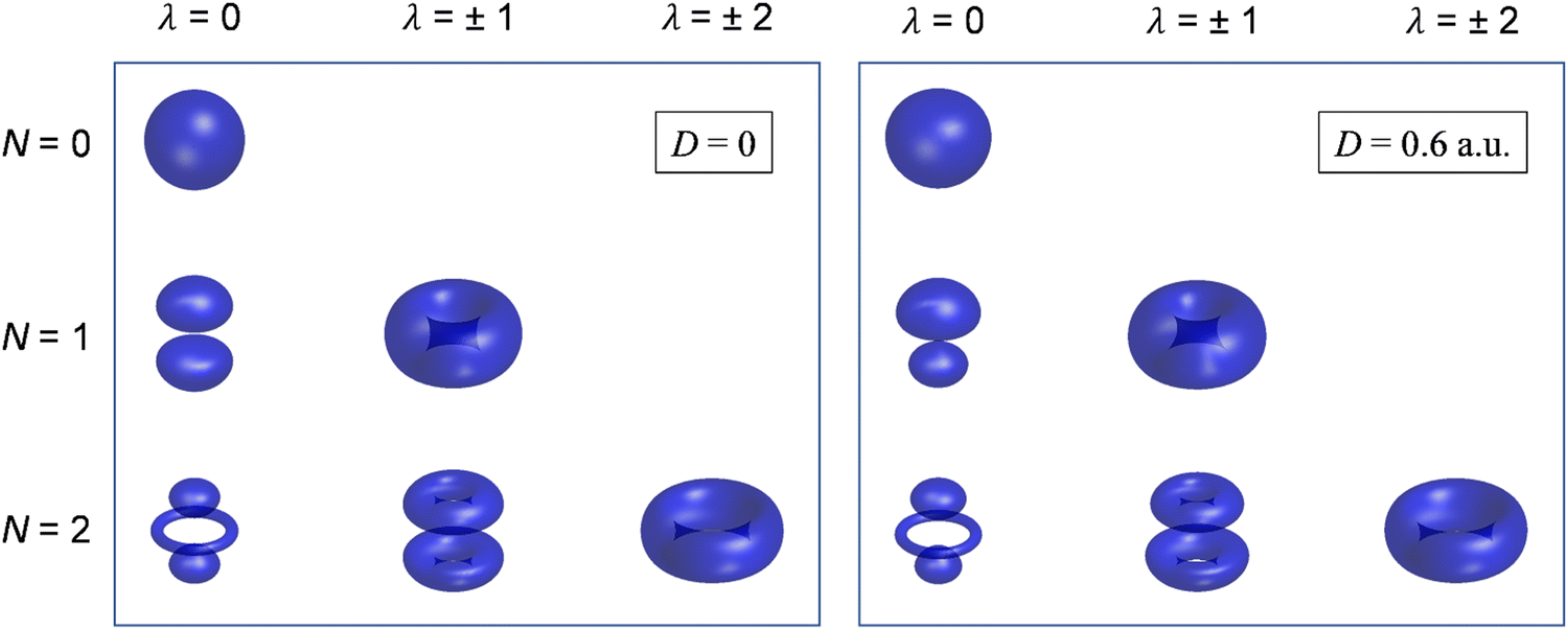 | ||
Fig. 9 Continuum probability density,  , influenced by point dipole of strengths 0 (left) and 0.6 a.u. (right). , influenced by point dipole of strengths 0 (left) and 0.6 a.u. (right). | ||
We used the point-dipole representation of the continuum, eqn (11)–(13), within an updated version of our existing Matlab code,5 to calculate the β(ε) trends in SO− photodetachment for various dipole-moment values assigned to the neutral residue. As noted previously, the relevant Dyson orbitals shown in Fig. 3 are reminiscent of lopsided d-like orbitals, so this work is the first application of this approach to non-σ Dyson orbitals. In Fig. 10, β(ε) curves for the three transitions, SO(X3Σ−, a1Δ, b1Σ+; v′) ← SO−(X2Π) are shown at different dipole moment values (given in atomic units). The left half of the figure, (a)–(c), presents the results obtained using the EOM-EA/SF Dyson orbitals from Fig. 3(a). The right half, Fig. 10(d) and (e), with the EOM-IP orbitals from Fig. 3(b). As a reminder, both methods used the aug-cc-pVTZ+5s5p5d5f basis set. We repeated the calculations with Dyson orbitals obtained using the aug-cc-pVQZ+2s2p1d1f1g basis set, with nearly identical results (not shown).
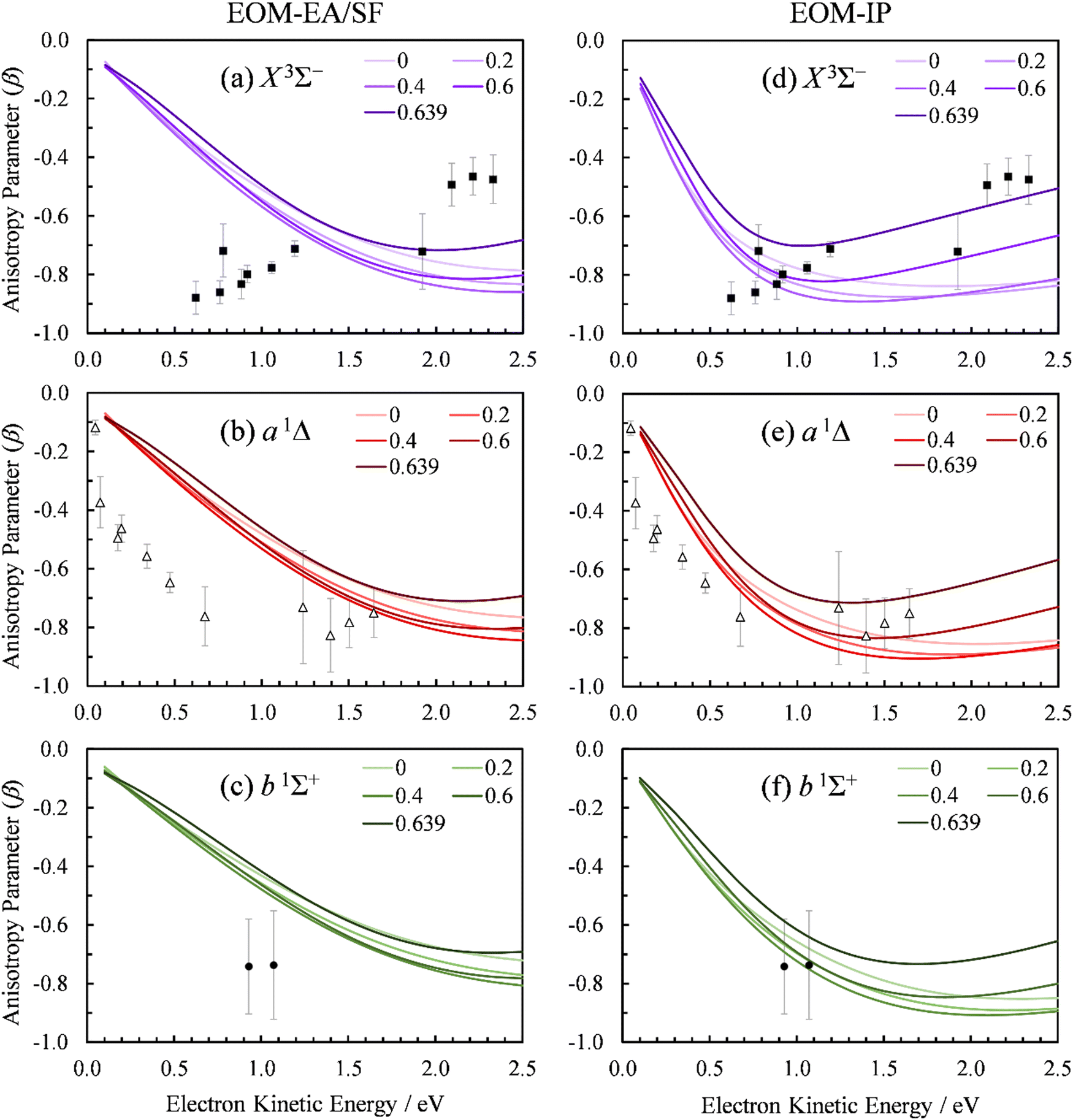 | ||
| Fig. 10 Experimental and computed PADs for SO− (X2Π) photodetachment to the SO neutral states: (a) and (d) X3Σ−, (b) and (e) a1Δ, (c) and (f) b1Σ+. The calculations in the left column (a)–(c) used the EOM-EA/SF-CCSD Dyson orbitals; those on the right (d)–(f)—EOM-IP-CCSD. PADs calculated with varying point dipole strength (in a.u.) are shown. Symbols represent the experimental data reproduced from Fig. 2(a). | ||
For D = 0, the curves in Fig. 10(a)–(c) coincide with the plane-wave ezDyson calculations in Fig. 5(a), while those in Fig. 10(d)–(f) with their counterparts in Fig. 5(b). This is expected: with the dipole moment set to zero both types of calculations amount to the free-particle treatment of the detached electron. As D is increased, the curves calculated using eqn (11)–(13) deviate from the free-particle limit.
The three transitions appear to be affected in a similar manner, consistent with the similar shapes of the corresponding Dyson orbitals. The location of the β(ε) minimum consistently shifts to lower eKE as D increases, and the width of the minimum becomes narrower. At the same time, the depth of the minimum increases as D changes from zero to ∼0.4 a.u., but this trend reverses for larger values of D. For D ≥ 0.4 a.u., the entire β(ε) curve for each of the transitions gradually shifts upward with increasing D. This parametric trend accelerates as D approaches the critical value for binding an = 0 electron in the point-dipole field, Dc = 0.6393 a.u. (1.625 Debye).4 Our current implementation only allows for D values below the critical dipole (i.e., in the absence of dipole bound states). Above the critical limit, the unphysical nature of the point dipole model becomes problematic. At the origin, an infinite number of deeply bound states exist – and more pertinently, the radial wave function oscillates rapidly as the origin is approached.77 In future versions of our code, this problem will be addressed using a more physically reasonable description of the dipole as two separated point charges.78
The rapid anisotropy change just below Dc signals significant changes in the outgoing electron wave function as its s component approaches the binding limit in the point-dipole field. To emphasize the rapid evolution of the β(ε) trends as D → Dc, all graphs in Fig. 10 include the curves calculated with D = 0.6390 a.u. (i.e., just below Dc). In each case, the difference between the 0.6390 and 0.6 a.u. curves is more significant than that between 0.6 and 0.4 a.u.
The D → Dc regime is relevant to SO− photodetachment, because the SO(X3Σ−) dipole moment is 0.610(8) a.u., while that for the a1Δ state is 0.52(2) a.u.7 Both of these published dipoles correspond to the respective neutral equilibrium geometries. Since photodetachment is a vertical process, dipole moment values corresponding to neutral states at the geometry of the anion are more appropriate. Our CCSD/aug-cc-pVTZ calculations indicate significant increases (by 0.16 and 0.22 a.u., respectively) in the dipole moment for the triplet and singlet channels. This is due to the larger charge separation as the bond length is extended from the neutral to the anion equilibrium value. Inclusion of these corrections increases D to above the fixed dipole 0.6393 a.u. critical value.
The 0.6393 a.u. (1.625 Debye) critical dipole for binding an electron is based on a fixed-dipole approximation.4 This limit is the same regardless of whether a point-dipole or a two-center separated-charge representation is employed.79 Of course, real molecules are neither fixed nor point dipoles, and the accepted requirement for a molecule to support a dipole-bound anion state is for D to be in excess of about 0.94 a.u. (2.4 Debye). Similar limitations are likely to apply to our analysis. Nonetheless, the results in Fig. 10 clearly show that, similar to previous observation for a σ orbital,5 π*-orbital detachment is affected by the presence of a strong dipole in the neutral residue. For a proper understanding of photoelectron ejection dynamics, even in cases where dipole-bound states are not supported, long-range electron–dipole interactions need to be considered.
The above approach, employing the solutions of the fixed point-dipole Schrödinger equation to evaluate the 〈ψelk|rY1,0|ϕd〉 integrals, demonstrates the importance of accounting for the interaction between dipole moment and the electron in PAD modeling. Next, we present an alternative approach that models SO as two separate electron wave emitters with opposite but equal charges.
 | (14) |
For the multi-center PAD calculations in this section, Dyson orbitals were computed using both the EOM-IP-CCSD and the EOM-EA/SF-CCSD methods described above, but with the standard aug-cc-pVTZ basis set (without augmenting it with additional highly diffuse functions). This is to avoid artifacts from the diffuse functions that result in electron density far from the atom centers [e.g., see the X3Σ− EOM-EA/SF Dyson orbital in Fig. 3(a)]. β(ε) was computed using both plane (ZS, ZO = 0) and Coulomb (ZS, ZO ≠ 0) waves to test the effect of varying the effective charges on oxygen (ZO) and sulfur (ZS), under the constraint ZO = − ZS. Since oxygen is more electronegative than sulfur, we use a negative charge on O and a positive charge on S. The results for ZS = 0, 0.05, 0.10, 0.15, and 0.20, obtained using the X3Σ− channel Dyson orbital (Fig. 3) are shown in Fig. 11(a) for EOM-EA/SF-CCSD and Fig. 11(b) for EOM-IP-CCSD. The results with the two methods are quantitatively different, indicating a high sensitivity to the diffuseness of the Dyson orbital. However, both exhibit the same trend and lead to a conclusion that is consistent with the point dipole calculations above—the increasing strength of the interaction of the ejected electron with the polar core leads to a shifting of the β(ε) minimum to lower eKE. For the EOM-IP-CCSD Dyson orbital, the multi-center calculation using Coulomb waves with ZS = 0.10 and ZO = −0.10 give the best agreement with experiment, while for EOM-EA/SF-CCSD the best agreement is when using ZS = 0.15 and ZO = −0.15.
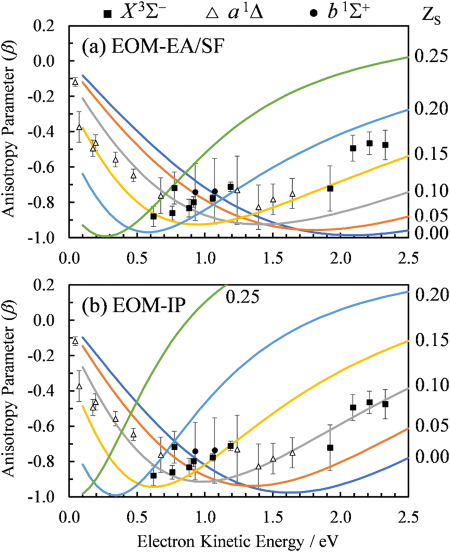 | ||
| Fig. 11 Curves: Photoelectron anisotropy parameter (β) as a function of eKE for SO− computed using the multi-center Coulomb-wave treatment of the photoelectron wave function. Symbols: Experimental data reproduced from Fig. 2(a). The calculations in (a) used EOM-EA-CCSD to EOM-SF-CCSD Dyson orbitals, while those in (b) EOM-IP-CCSD. The aug-cc-pVTZ basis set was used in both cases. Results are shown with varying charges ZS and ZO = −ZS for photodetachment to the X3Σ− state of SO. The ZS values for various curves are indicated on the right. | ||
The dipole moment of SO at its X3Σ− equilibrium bond length is 0.610(8) a.u. (1.55 Debye).7 Dividing by the equilibrium bond length of SO−, 1.592 Å (from CCSD/aug-cc-pVTZ calculations), the partial charge on sulfur is estimated to be ZS = 0.20 (assuming that the dipole moment does not change from its adiabatic value). A similar estimate for the a1Δ channel (D = 0.52(2) a.u.)7 yields ZS = 0.17. These estimates are in reasonably close to the values suggested by the above multi-center calculations. Due to the approximate treatment of the photoelectron wave function and the sensitivity of the multi-center approach to the details of the method and basis set, the better quantitative agreement for the EOM-EA/SF-CCSD calculations is likely coincidental and does not mean that the EOM-EA/SF-CCSD method is more accurate than EOM-IP-CCSD for this system.
The improved agreement of the multi-center calculations with the experiment reaffirms the need for a theory to compute PADs and anisotropies using a description of the continuum that accounts for interaction of the outgoing photoelectron waves with the molecular dipole.
5. Summary and conclusions
We have reported a photoelectron imaging and ab initio study of the angular distributions in SO− photodetachment accessing the X3Σ−, a1Δ, and b1Σ+ electronic states of SO, and discussed the results in comparison to the PADs determined previously for O2−. Taking a bird's eye view of the experimental data for the three transitions in aggregate, the observed β vs. eKE anisotropy curve follows the general trend expected for π* orbital photodetachment, but compared to O2−, the minimum of the SO− curve is shifted to smaller eKE.Several ab initio models using Dyson orbitals were considered. It is most revealing that neglect of the SO dipole moment yields β(ε) curves with shallow minima mostly at ε > 1.5 eV. This predicted behavior is similar to the O2− results, but inconsistent with the SO− experimental data. On the other hand, the models that include the SO dipole into the theoretical framework yield a much-improved agreement with the experiment. These models are: the point dipole-field model with D > 0.6 a.u. [Fig. 10(d)–(f)] and the multi-center model with ZS = 0.10–0.15 [Fig. 11]. While these are two different approaches for accounting for the SO dipole–photoelectron interaction, their results are consistent and lead to the overarching conclusion: The distinctions between the O2− and SO− PADs should be attributed mainly to the electron–dipole interactions in the exit channel of SO− photodetachment, rather than the different shapes of the detachment orbitals. A similar conclusion was previously reached for CN−;5 here we presented the first extension of the dipole-field model to detachment from non-σ orbitals.
The computed photoelectron angular distributions are sensitive to the long-range behavior of wave functions and, therefore, the exact method for calculating the Dyson orbitals. At a relatively low-level of treatment (up to double excitations), the EOM-IP approach using the anionic reference yields more diffuse Dyson orbitals and quantitatively different β(ε) curves compared to the EOM-EA/SF method using the neutral reference. For most of the calculations in this work, the EOM-IP Dyson orbital calculations yield the more accurate β(ε) curves. This is consistent with a known behavior of these methods in calculations using closed-shell references, e.g., the effect of triple excitations is more important for EOM-EA than for EOM-IP. Hence, we expect the differences between the two approaches to be reduced when triple excitations are included.
Nevertheless, the sensitivity of the results to the correlation level in calculations of Dyson orbitals does not affect our main conclusion, that the electron–dipole interactions must be considered for accurate modeling of PADs. We emphasize that for this effect to be prominent, the dipole moment D of the neutral residue does not have to exceed the critical value Dc for binding an electron in the dipole field. Nonetheless, as D is increased towards Dc, the parametric dependence of PADs on the former increases sharply. In the future it would be interesting to incorporate the (non-Born-Oppenheimer) effects associated with molecular rotation and examine these effects in the regime of D ≥ Dc, which is not accessible in the current model implementation.
Finally, we highlight the pitfalls of empirical fitting approaches, such as those often used in conjunction with the Cooper–Zare or l-mixing models. These models contain physical variables (transition-dipole matrix elements, phase shifts, etc.), which can be determined in one of two ways: via ab initio calculations or by treating them as adjustable parameters while fitting the model to experimental data. It is the latter approach that can be problematic, for given several empirical parameters it is usually possible to match the model to the experimental results, without guarantee that the “best” parameter values are physically meaningful. Ab initio calculations—like those implemented in ezDyson with correlated Dyson orbitals—do not always support the parameter values giving the best fit. Such discrepancies help one learn about essential physics of the problem—in the present case, the effect of the core dipole moment on the emitted photoelectrons.
Conflicts of interest
AIK is the president and part-owner of Q-Chem.Acknowledgements
A. S. and A. I. K. acknowledge financial support for this work by the U.S. National Science Foundation through grants CHE-1664732, CHE-2153986 (A. S.), and CHE-2154482 (A. I. K.). S. G. acknowledges the donors of the American Chemical Society Petroleum Research Fund for support through PRF#60837-DNI6. This work used the Extreme Science and Engineering Discovery Environment (XSEDE) Expanse supercomputer at the San Diego Supercomputer Center through allocation CHE180027.References
- K. L. Reid, Annu. Rev. Phys. Chem., 2003, 54, 397–424 CrossRef CAS.
- A. Sanov, Annu. Rev. Phys. Chem., 2014, 65, 341–363 CrossRef CAS PubMed.
- E. P. Wigner, Phys. Rev., 1948, 73, 1002–1009 CrossRef CAS.
- K. D. Jordan and F. Wang, Annu. Rev. Phys. Chem., 2003, 54, 367–396 CrossRef CAS PubMed.
- C. A. Hart, J. Lyle, J. Spellberg, A. I. Krylov and R. Mabbs, J. Phys. Chem. Lett., 2021, 12, 10086–10092 CrossRef CAS PubMed.
- R. Thomson and F. W. Dalby, Can. J. Phys., 1968, 46, 2815–2819 CrossRef CAS.
- C. R. Byfleet, A. Carrington and D. K. Russell, Mol. Phys., 1971, 20, 271–277 CrossRef CAS.
- K. P. Huber and H. G. Herzberg, Molecular Spectra and Molecular Structure. IV. Constants of Diatomic Molecules, Van Nostrund Reinhold, New York, 1979 Search PubMed.
- R. J. Celotta, R. A. Bennett, J. Levine, J. L. Hall and M. W. Siegel, Phys. Rev. A: At., Mol., Opt. Phys., 1972, 6, 631–642 CrossRef CAS.
- F. A. Akin, L. K. Schirra and A. Sanov, J. Phys. Chem. A, 2006, 110, 8031–8036 CrossRef CAS PubMed.
- R. Mabbs, F. Mbaiwa, J. Wei, M. Van Duzor, S. T. Gibson, S. J. Cavanagh and B. R. Lewis, Phys. Rev. A: At., Mol., Opt. Phys., 2010, 82, 011401 CrossRef.
- M. Van Duzor, F. Mbaiwa, J. Wei, T. Singh, R. Mabbs, A. Sanov, S. J. Cavanagh, S. T. Gibson, B. R. Lewis and J. R. Gascooke, J. Chem. Phys., 2010, 133, 174311 CrossRef PubMed.
- E. Lellouch, D. F. Strobel, M. J. S. Belton, M. E. Summers, G. Paubert and R. Moreno, Astrophys. J., 1996, 459, L107–L110 CAS.
- M. Y. Zolotov and B. Fegley, Icarus, 1998, 132, 431–434 CrossRef CAS.
- J. Moses, M. Y. Zolotov and B. Fegley, Icarus, 2002, 156, 76–106 CrossRef CAS.
- C. T. Russell and M. G. Kivelson, J. Geophys. Res., 2001, 106, 33267–33272 CrossRef CAS.
- B. E. Turner, Astrophys. J., 1994, 430, 727 CrossRef CAS.
- D. C. Lis, D. M. Mehringer, D. Benford, M. Gardner, T. G. Phillips, D. Bockelée-Morvan, N. Biver, P. Colom, J. Crovisier, D. Despois and H. Rauer, Earth, Moon, Planets, 1997, 78, 13–20 CrossRef CAS.
- C. A. Gottlieb, E. W. Gottlieb, M. M. Litvak, J. A. Ball and H. Penfield, Astrophys. J., 1978, 219, 77–94 CrossRef CAS.
- M. Gargaud, R. Amils, J. C. Quintanilla, H. J. CleavesII, W. M. Irvine, D. L. Pinti and M. Viso, Encyclopedia of Astrobiology, Springer, Berlin, Heidelberg, 2011 Search PubMed.
- B. E. Turner, Astrophys. J., 1996, 468, 694 CrossRef CAS.
- A. Heithausen, U. Corneliussen and V. Grossmann, Astron. Astrophys., 1995, 301, 941 CAS.
- L. M. Chernin, C. R. Masson and G. A. Fuller, Astrophys. J., 1994, 436, 741 CrossRef CAS.
- F. Wu, X. R. Chen and B. R. Weiner, J. Am. Chem. Soc., 1996, 118, 8417–8424 CrossRef CAS.
- S. Ono, Annu. Rev. Earth Planet. Sci., 2017, 45, 301–329 CrossRef CAS.
- T. Storelvmo, Annu. Rev. Earth Planet. Sci., 2017, 45, 199–222 CrossRef CAS.
- P. L. Ward, Thin Solid Films, 2009, 517, 3188–3203 CrossRef CAS.
- W. W. Clark and F. C. De Lucia, J. Mol. Spec., 1976, 60, 332–342 CrossRef CAS.
- B. S. Jursic, J. Mol. Struct., 1999, 467, 187–193 CrossRef CAS.
- M. Bogey, S. Civiš, B. Delcroix, C. Demuynck, A. F. Krupnov, J. Quiguer, M. Y. Tretyakov and A. Walters, J. Mol. Spectrosc., 1997, 182, 85–97 CrossRef CAS.
- M. L. Polak, B. L. Fiala, K. M. Ervin and W. C. Lineberger, J. Chem. Phys., 1991, 94, 6926–6927 CrossRef CAS.
- E. Surber and A. Sanov, J. Chem. Phys., 2002, 116, 5921–5924 CrossRef CAS.
- R. Mabbs, E. Surber and A. Sanov, Analyst, 2003, 128, 765–772 RSC.
- A. T. J. B. Eppink and D. H. Parker, Rev. Sci. Instrum., 1997, 68, 3477–3484 CrossRef CAS.
- V. Dribinski, A. Ossadtchi, V. A. Mandelshtam and H. Reisler, Rev. Sci. Instrum., 2002, 73, 2634–2642 CrossRef CAS.
- A. J. R. Heck and D. W. Chandler, Annu. Rev. Phys. Chem., 1995, 46, 335–372 CrossRef CAS PubMed.
- C. N. Yang, Phys. Rev., 1948, 74, 764–772 CrossRef CAS.
- J. Cooper and R. N. Zare, J. Chem. Phys., 1968, 48, 942–943 CrossRef CAS.
- J. Cooper and R. N. Zare, J. Chem. Phys., 1968, 49, 4252 CrossRef.
- H. A. Bethe, Handbuch der Physik, 1933, 24, 483 Search PubMed.
- H. A. Bethe and E. E. Salpeter, Quantum Mechanics of One- and Two-Electron Atoms, Springer-Verlag; Academic Press Inc., Berlin, New York, 1957 Search PubMed.
- K. J. Reed, A. H. Zimmerman, H. C. Andersen and J. I. Brauman, J. Chem. Phys., 1976, 64, 1368–1375 CrossRef CAS.
- D. Hanstorp, C. Bengtsson and D. J. Larson, Phys. Rev. A: At., Mol., Opt. Phys., 1989, 40, 670–675 CrossRef CAS PubMed.
- J. C. Tully, R. S. Berry and B. J. Dalton, Phys. Rev., 1968, 176, 95–105 CrossRef CAS.
- A. D. Buckingham, B. J. Orr and J. M. Sichel, Philos. Trans. R. Soc., A, 1970, 268, 147–157 CrossRef CAS.
- E. Surber, R. Mabbs and A. Sanov, J. Phys. Chem. A, 2003, 107, 8215–8224 CrossRef CAS.
- C. C. Blackstone, A. A. Wallace and A. Sanov, Mol. Phys., 2021, 119, e1831636 CrossRef.
- D. Khuseynov, C. C. Blackstone, L. M. Culberson and A. Sanov, J. Chem. Phys., 2014, 141, 124312 CrossRef PubMed.
- A. Sanov, E. R. Grumbling, D. J. Goebbert and L. M. Culberson, J. Chem. Phys., 2013, 138, 054311 CrossRef PubMed.
- L. M. Culberson, C. C. Blackstone and A. Sanov, J. Phys. Chem. A, 2013, 117, 11760–11765 CrossRef CAS PubMed.
- L. M. Culberson, C. C. Blackstone, A. A. Wallace and A. Sanov, J. Phys. Chem. A, 2015, 119, 9770–9777 CrossRef CAS PubMed.
- E. R. Grumbling and A. Sanov, J. Chem. Phys., 2011, 135, 164301 CrossRef PubMed.
- E. R. Grumbling and A. Sanov, J. Chem. Phys., 2011, 135, 164302 CrossRef PubMed.
- K. M. Ervin, W. Anusiewicz, P. Skurski, J. Simons and W. C. Lineberger, J. Phys. Chem. A, 2003, 107, 8521–8529 CrossRef CAS.
- A. I. Krylov, J. Chem. Phys., 2020, 153, 080901 CrossRef CAS PubMed.
- J. V. Ortiz, J. Chem. Phys., 2020, 153, 070902 CrossRef CAS PubMed.
- T. Moitra, A. Ponzi, H. Koch, S. Coriani and P. Decleva, J. Phys. Chem. Lett., 2020, 11, 5330–5337 CrossRef CAS PubMed.
- M. Díaz–Tinoco, H. H. Corzo, F. Pawłowski and J. V. Ortiz, Mol. Phys., 2019, 117, 2275–2283 CrossRef.
- S. Gozem, A. O. Gunina, T. Ichino, D. L. Osborn, J. F. Stanton and A. I. Krylov, J. Phys. Chem. Lett., 2015, 6, 4532–4540 CrossRef CAS PubMed.
- M. Stener, G. Fronzoni, D. Toffoli and P. Decleva, Chem. Phys., 2002, 282, 337–351 CrossRef CAS.
- I. Powis, Chem. Phys., 1995, 201, 189–201 CrossRef CAS.
- M. Ruberti, V. Averbukh and P. Decleva, J. Chem. Phys., 2014, 141, 164126 CrossRef CAS PubMed.
- A. I. Krylov, Annu. Rev. Phys. Chem., 2008, 59, 433–462 CrossRef CAS PubMed.
- A. I. Krylov, Chem. Phys. Lett., 2001, 338, 375–384 CrossRef CAS.
- S. V. Levchenko and A. I. Krylov, J. Chem. Phys., 2004, 120, 175–185 CrossRef CAS PubMed.
- M. Nooijen and R. J. Bartlett, J. Chem. Phys., 1995, 102, 3629–3647 CrossRef CAS.
- Y. H. Shao, Z. T. Gan, E. Epifanovsky, A. T. B. Gilbert, M. Wormit, J. Kussmann, A. W. Lange, A. Behn, J. Deng, X. T. Feng, D. Ghosh, M. Goldey, P. R. Horn, L. D. Jacobson, I. Kaliman, R. Z. Khaliullin, T. Kus, A. Landau, J. Liu, E. I. Proynov, Y. M. Rhee, R. M. Richard, M. A. Rohrdanz, R. P. Steele, E. J. Sundstrom, H. L. Woodcock, P. M. Zimmerman, D. Zuev, B. Albrecht, E. Alguire, B. Austin, G. J. O. Beran, Y. A. Bernard, E. Berquist, K. Brandhorst, K. B. Bravaya, S. T. Brown, D. Casanova, C. M. Chang, Y. Q. Chen, S. H. Chien, K. D. Closser, D. L. Crittenden, M. Diedenhofen, R. A. DiStasio, H. Do, A. D. Dutoi, R. G. Edgar, S. Fatehi, L. Fusti-Molnar, A. Ghysels, A. Golubeva-Zadorozhnaya, J. Gomes, M. W. D. Hanson-Heine, P. H. P. Harbach, A. W. Hauser, E. G. Hohenstein, Z. C. Holden, T. C. Jagau, H. J. Ji, B. Kaduk, K. Khistyaev, J. Kim, J. Kim, R. A. King, P. Klunzinger, D. Kosenkov, T. Kowalczyk, C. M. Krauter, K. U. Lao, A. D. Laurent, K. V. Lawler, S. V. Levchenko, C. Y. Lin, F. Liu, E. Livshits, R. C. Lochan, A. Luenser, P. Manohar, S. F. Manzer, S. P. Mao, N. Mardirossian, A. V. Marenich, S. A. Maurer, N. J. Mayhall, E. Neuscamman, C. M. Oana, R. Olivares-Amaya, D. P. O'Neill, J. A. Parkhill, T. M. Perrine, R. Peverati, A. Prociuk, D. R. Rehn, E. Rosta, N. J. Russ, S. M. Sharada, S. Sharma, D. W. Small, A. Sodt, T. Stein, D. Stuck, Y. C. Su, A. J. W. Thom, T. Tsuchimochi, V. Vanovschi, L. Vogt, O. Vydrov, T. Wang, M. A. Watson, J. Wenzel, A. White, C. F. Williams, J. Yang, S. Yeganeh, S. R. Yost, Z. Q. You, I. Y. Zhang, X. Zhang, Y. Zhao, B. R. Brooks, G. K. L. Chan, D. M. Chipman, C. J. Cramer, W. A. Goddard, M. S. Gordon, W. J. Hehre, A. Klamt, H. F. Schaefer, M. W. Schmidt, C. D. Sherrill, D. G. Truhlar, A. Warshel, X. Xu, A. Aspuru-Guzik, R. Baer, A. T. Bell, N. A. Besley, J. D. Chai, A. Dreuw, B. D. Dunietz, T. R. Furlani, S. R. Gwaltney, C. P. Hsu, Y. S. Jung, J. Kong, D. S. Lambrecht, W. Z. Liang, C. Ochsenfeld, V. A. Rassolov, L. V. Slipchenko, J. E. Subotnik, T. Van Voorhis, J. M. Herbert, A. I. Krylov, P. M. W. Gill and M. Head-Gordon, Mol. Phys., 2015, 113, 184–215 CrossRef CAS.
- S. Gozem and A. I. Krylov, Wiley Interdiscip. Rev.: Comput. Mol. Sci., 2021, 12, e1546 Search PubMed.
- C. M. Oana and A. I. Krylov, J. Chem. Phys., 2009, 131, 124114 CrossRef PubMed.
- C. M. Oana and A. I. Krylov, J. Chem. Phys., 2007, 127, 234106 CrossRef PubMed.
- M. Bak and N. C. Nielsen, J. Magn. Reson., 1997, 125, 132–139 CrossRef CAS PubMed.
- R. Mabbs, E. R. Grumbling, K. Pichugin and A. Sanov, Chem. Soc. Rev., 2009, 38, 2169–2177 RSC.
- S. Gozem, R. Seidel, U. Hergenhahn, E. Lugovoy, B. Abel, B. Winter, A. I. Krylov and S. E. Bradforth, J. Phys. Chem. Lett., 2020, 11, 5162–5170 CrossRef CAS PubMed.
- L. G. Dodson, J. D. Savee, S. Gozem, L. Shen, A. I. Krylov, C. A. Taatjes, D. L. Osborn and M. Okumura, J. Chem. Phys., 2018, 148, 184302 CrossRef PubMed.
- M. J. Abplanalp, S. Gozem, A. I. Krylov, C. N. Shingledecker, E. Herbst and R. I. Kaiser, Proc. Natl. Acad. Sci. U. S. A., 2016, 113, 7727–7732 CrossRef CAS.
- J. Siegel, J. L. Dehmer and D. Dill, Phys. Rev. A: At., Mol., Opt. Phys., 1981, 23, 632–640 CrossRef CAS.
- C. Greene, U. Fano and G. Strinati, Phys. Rev. A: At., Mol., Opt. Phys., 1979, 19, 1485–1509 CrossRef CAS.
- G. A. Gallup, Phys. Rev. A: At., Mol., Opt. Phys., 2009, 80, 012511 CrossRef.
- K. Connolly and D. J. Griffiths, Am. J. Phys., 2007, 75, 524–531 CrossRef.
| This journal is © the Owner Societies 2022 |