A pendant drop method for the production of calibrated double emulsions and emulsion gels
Alexandre Schmita,
Laurent Courbina,
Mélanie Marquisb,
Denis Renardb and
Pascal Panizzaa
aInstitut de Physique de Rennes, UMR CNRS 6251, Campus Beaulieu, Université Rennes 1, 263 Avenue du Général Leclerc, 35000 Rennes, France
bINRA, Biopolymères Interactions Assemblages UR1268, F-44300 Nantes, France
First published on 19th June 2014
Abstract
We describe a pendant drop method that allows one to produce double emulsions in a controllable way. Using a co-flowing drop-maker, we generate a periodic train made of monodisperse droplets that is directed toward the end of a capillary tube where a pendant drop forms. When this drop detaches from the tip of the capillary under the influence of gravity, it may or may not encapsulate one or several droplets depending on experimental conditions. We discuss the advantages of this method when compared with other techniques described in the literature and we present a simple model that predicts well the mean volume of the outer drops and the mean number of encapsulated droplets per drop as a function of the various physical parameters at play in experiments. We illustrate the high potentiality of this simple method by producing well-calibrated emulsion gels of large sizes and we discuss possible applications.
1. Introduction
Water-in-oil-in-water (W/O/W) double emulsions are complex liquid dispersions in which oil globules containing small aqueous droplets are dispersed in an aqueous continuous phase.1 Increasing attention has been devoted to these systems with the aim of exploiting their double (or multiple) compartment structure. Among the interesting features of such materials, one can mention the high capacity of entrapment of hydrophilic actives, their ability to introduce incompatible substances in the same system, the improvement of the performance of actives, and the protection and the sustained release of chemical substances initially entrapped in the internal small droplets.2 The stability of multiple emulsions was extensively studied during the past two decades by preparing emulsions with emulsifiers of opposite solubility. Both emulsifiers mix at the liquid interfaces and the stability of the films with respect to coalescence is governed by the composition of the binary mixtures.2 Coalescence in multiple emulsions can occur in diverse ways:2–4 (i) between small inner droplets, (ii) between large globules, and (iii) between the external phase and the small droplets dispersed within the globules. Because of osmotic pressure gradients between the two aqueous phases in W/O/W emulsions, water may migrate either from the internal to the external phase or vice versa. The direction of migration is governed by the relative difference in osmotic pressure between the two phases and by the Laplace pressure.5 Water transport may therefore be critical in the various applications using multiple emulsions. Stability under storage conditions with minimum leakage of the encapsulated species, when emulsions are used as delivery systems, is thus a mandatory prerequisite for W/O/W emulsions to be of practical use. Recent studies in the presence of amphiphilic polymers, proteins, and solid colloidal particles reveal that coalescence can be inhibited and that diffusive transport may be extremely slow.6 The storage stability of these materials based on macromolecular or particulate stabilizers paves the way to new developments for drug or nutrient delivery systems based on double-emulsion technologies. However, the use of W/O/W double emulsions for food applications, for instance, remains limited because of the lack of suitable food-grade emulsifiers and stabilizers for the inner and outer emulsions.7A strategy that is employed to overcome the problem of the metastable nature of double emulsions, i.e. to prevent flocculation and coalescence of the small droplets, is to arrest the system by gelling the large globules. This strategy that is often used in manufactured or traditional food products relies on materials called emulsion gels or filled hydrogel particles in the literature.8–10 The initial stage in emulsion gel formulation usually involves making a stabilized emulsion by using a single protein or a mixture of proteins as an emulsifier. The formulation procedure may involve the incorporation of a hydrocolloid stabilizer during emulsification, or may be added after the formation of the emulsion, with further implications for the state of flocculation.11–13 For protein-based systems, the most widely employed methods are heating, acidification and enzyme treatment.9–14 These emulsion gels find applications in the food and cosmetic industries as carriers to improve the delivery of functional lipophilic components,10 e.g. the encapsulation of probiotics in granular scale alginate microgels via an emulsion gelation route.15 Other industrial developments deal with the satiety control as being targeted by manufacturers to improve the health status of consumers. Li et al. (2012) suggested that the encapsulation of lipophilic compounds in large microgels could modulate the satiety response by two mechanisms: (1) large microgels would be transported more slowly through the stomach and intestinal tract and (2) the rate of release of lipophilic compounds from the biopolymer shell or network would be limited by the large size.16 Even more importantly, the epidemic of obesity in many developed societies is presenting the food industry with the challenge of developing new food structures with appealing taste and texture but without the current strong reliance on conventional functional ingredients such as fats, refined sugars and added salt. Emulsion gels or filled biopolymer particles could be good candidates as being both fat-replacers and texturing agents in which the efficient encapsulation of salts and other flavor compounds will enhance the consumer's perceived in-mouth taste experience.17 For all these applications, emulsification is commonly used for many combinations of biopolymers and oils to produce emulsion gels or filled polymer particles where the oil-in-water (O/W) or water-in-oil (W/O) emulsion is entrapped in a gelled polymeric matrix.
The mechanical energy required for the formation of small droplets can be provided by a wide range of homogenizers and high pressure mixing devices.18 However, these efficient and cost-effective methods for industrial applications suffer from a large size polydispersity of small droplets in the O/W or W/O emulsions and the deformation and subsequent break-up of gelled particles. Emulsification by spin disk atomization for instance has the advantage of offering very high production rates but particles are generally highly polydisperse when created with this technique. By contrast, membrane emulsification allows one to produce filled polymer particles that are monodisperse and spherical. Yet, because of the limited flow rates in this type of emulsification it is difficult to scale-up the method appropriately. Microfluidic devices are small-scale systems that are suitable for the production of monodisperse, uniform emulsion gels or filled hydrogel particles. Although it is unlikely that microfluidics could be scaled-up adequately and economically for general food or non-food uses, the technology can be used to obtain valuable insights into the controlling parameters necessary for the design of large scale processing equipments.19 Nevertheless, at the scale of a laboratory, microfluidics can be used to produce (gelled) particles with specific shapes and internal structures. In addition, these manufactured materials being monodisperse, microfluidics offers possibilities for the prediction and fine tuning of the rate of release of actives such as flavors or nutraceuticals to obtain desired product characteristics.20–22 Microfluidics is also one of the few reliable and repeatable methods for producing double emulsions such as W/O/W with monodisperse encapsulated droplets and particles.18 Filled polymer particles with micrometer-scale dimensions can thus be produced with excellent control through the use of droplet-based microfluidics. Additionally, for applications in the food industry, the rationale design of filled biopolymer particles using droplet-based microfluidics should improve the knowledge on the actives release profiles, the literature beginning only recently to document this topic.22 The microfluidic fabrication of double emulsions is usually achieved through a two-step drop formation method.23,24 A periodic train of monodisperse droplets is first produced using a drop maker, such as a flow focusing geometry25 or a T junction.26 The train is then directed toward a second drop maker where large monodisperse drops form and may encapsulate the small droplets. By operating on drops one at a time, this method offers unprecedented control over the number and sizes of the encapsulated droplets as well as the sizes of the outer drops when compared to other emulsification techniques.23,27 Serially positioned hydrophobic and hydrophilic microchannels are necessary to form successively aqueous and organic drops in a single microdevice. W/O/W or oil-in-water-in-oil (O/W/O) double emulsions can then be generated by reversing the order of hydrophobic and hydrophilic channels.28,29 In planar polydimethylsiloxane-based microfluidics, such a control over the wetting properties of the channels requires localized modifications of the surface chemistry which limits the flexibility in use of the technology to manufacture complex fluid architectures, e.g. high-order multiple emulsions.30 By contrast, microfluidic and millifluidic devices made of an assembly of co-axial flow focusing geometries connected to each other via glass capillaries or commercial tubing offer a greater versatility with respect to wetting conditions and modularity.31,32 By assembling together elementary modules and integrating their corresponding functions, one can indeed create on demand modular set-ups that can be used to engineer a myriad of dispersed materials such as multiple emulsions, double emulsions having inner droplets with several chemical compositions, polymersomes or solid particles with liquid compartments having characteristic sizes ranging from typically 50 μm up to a few millimeters.33 Double emulsions with such large sizes draw much commercial interests in the food and cosmetic industries as their visible internal structures, i.e. the encapsulated droplets, is direct product marketing.
Here we present a pendant drop method allowing one to produce large-sized double emulsions in a simple and controllable manner. In contrast to previously described bottom-up microfluidic and millifluidic approaches, this method does not require to serially combine two drop makers having both hydrophobic and hydrophilic wetting properties. As a result, the presented method is easy to implement and convenient to use. We generate a periodic train made of monodisperse droplets using a co-axial drop maker.31–34 The train flows downstream a capillary tube until it reaches the tube's end where a large pendant drop forms. Before detaching from the tip of the capillary because of gravity, this drop can encapsulate one or several droplets. This process creates a double emulsion over time. We present a simple model that describes the formation mechanism of such double emulsions and we successfully compare the predicted mean volume of the outer drops and the mean number of encapsulated droplets per drop to experimental findings. We then show that this method is well suited for the fabrication of calibrated gel emulsions.
2. Encapsulation of droplets using a pendant drop method
To describe the pendant drop method used to encapsulate droplets inside drops and to investigate the physics of the encapsulation process, we begin by working with a water–oil model system. Using a co-axial flow focusing geometry, we generate monodisperse W/O droplets (see a schematic of the experimental set-up in Fig. 1). Such a device consists of PEEK tubing (interior diameter (ID) = 31 μm and outside diameter (OD) = 205 μm, CIL Cluzeau Info Labo, France) centered inside another tube (ID = 2.5 mm and OD = 4 mm, CIL Cluzeau Info Labo, France). By infusing two immiscible fluids through the centered tube and the annular gap between the two tubes, monodisperse droplets are generated at the tip of the internal tube. In our experiments, the dispersed and continuous phases are an aqueous solution of sucrose [50 wt%] (Sigma Aldrich) and hexadecane (Sigma Aldrich) whose densities are ρd = 1229 kg m−3 and ρc = 770 kg m−3, respectively. Dispersed and continuous phases are respectively infused at constant flow rates Qfd and Qfc in the drop maker module using two syringe pumps (Harvard PHD 2000), both flow rates being controlled independently (see Fig. 1). The W/O droplets periodically form with a production period τ so that the tube is filled with a periodic train of droplets flowing at constant velocity. The resulting droplet train is directed toward a T junction (Upchurch Scientific) where additional continuous phase can be infused or withdrawn at a constant flow rate Qdc with a third pump through the lateral arm of this junction. This dilution module enables one to dilute (Qdc > 0) or to concentrate (Qdc < 0) the W/O emulsion while maintaining the volume of droplets unchanged.35 Tuning of Qdc results in an increase or decrease of the droplets' velocity and spacing downstream the module. In our experiments, the total flow rate is Q = Qfd + Qfc + Qdc. The train is then directed toward the end of the tube that is positioned vertically so that a pendant drop forms and eventually detaches from its tip because of gravity (Fig. 1). Before the pendant drop falls from the end of the tube, it may encapsulate one or several droplets. A high-speed camera (Photron MC2) records both the flow at the tip of the capillary and inside the tube. Images of the flow are processed with a custom-written MATLAB software to determine the period τ at which the droplets feed the tip of the tube, the time Tn elapsed between the production of the (n − 1)th drop and nth one, and the number Nn of encapsulated droplets in the nth drop. The volume of the nth drop is Vn = QTn. Series of both quantities [Nn] and [Tn] are obtained for large sequences of produced drops. Fig. 1 shows images of the flow taken at the drop maker and dilution modules of the device and at the tip of the capillary tube where the encapsulation of droplets inside drops occurs. For each set of our systematic experiments, Qfd and Qfc are kept constant and we change Qdc so that we only vary the volume fraction of the W/O emulsion while the droplet volume v = Qfdτ remains unchanged. In our experiments, v = 2–4 μL and the mean volume of the drops![[V with combining macron]](https://www.rsc.org/images/entities/i_char_0056_0304.gif) is a weakly increasing function of Q for a given v [see Fig. 2(a)]. As shown in Fig. 3(a), the mean number of encapsulated droplets per drop
is a weakly increasing function of Q for a given v [see Fig. 2(a)]. As shown in Fig. 3(a), the mean number of encapsulated droplets per drop ![[N with combining macron]](https://www.rsc.org/images/entities/i_char_004e_0304.gif) decreases continuously as the dilution, i.e. the flow rate Qdc, of the emulsion system increases; indeed, Fig. 3(a) shows the variations of with the total flow rate Q, Qfd and Qfc being constant for each set of data. Both and the mean volume are obtained from measurements carried out over sequences of typically 50 drops. Evidently, our method enables one to encapsulate droplets inside drops with very good and independent controls over v and .
decreases continuously as the dilution, i.e. the flow rate Qdc, of the emulsion system increases; indeed, Fig. 3(a) shows the variations of with the total flow rate Q, Qfd and Qfc being constant for each set of data. Both and the mean volume are obtained from measurements carried out over sequences of typically 50 drops. Evidently, our method enables one to encapsulate droplets inside drops with very good and independent controls over v and .
 | ||
| Fig. 1 Schematic of the set-up based on a pendant drop method used for the production of double emulsions and emulsion gels; defined are the experimental parameters. Shown are typical photographs of an emulsion in the formation and dilution modules and a drop of double emulsion created at the end of the capillary where encapsulation occurs. | ||
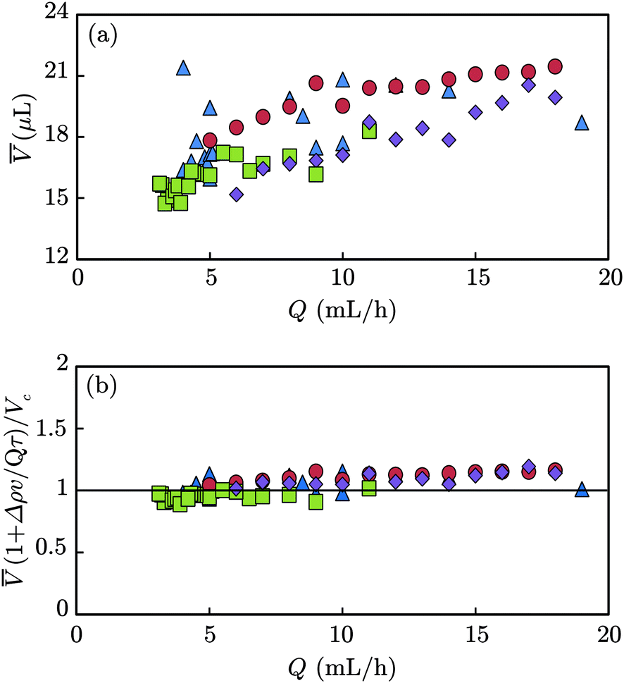 | ||
| Fig. 2 Water-in-oil-in-water double emulsions: variations of (a) versus Q and (b) (1 + Δρv/Qτ)/Vc versus Q. The solid line in Fig. 2(b) corresponds to eqn (1) derived in the text with Vc = 19 μL. The volume Vc of a pendant drop made of continuous phase only is determined by injecting the continuous oil phase through the capillary tube at a constant flow rate Q and measuring the mean time elapsed Tc between the detachment of two consecutive pendant drops; hence, Vc = QTc. The symbols stand for different values of v and τ: (red circles) v = 2.29 μL, τ = 8.24 s; (blue triangles) v = 2.62 μL, τ = 9.46 s; (green squares) v = 3.35 μL, τ = 12.09 s; (purple diamonds) v = 3.74 μL, τ = 4.51 s. As shown in Fig. 2(b), the predictions of eqn (1) concur very well with experiments. | ||
 | ||
| Fig. 3 Water-in-oil-in-water double emulsions: variations of (a) versus Q and (b) (Qτ + Δρv)/Vc versus Q. The solid line in Fig. 3(b) corresponds to eqn (2) derived in the text with Vc = 19 μL. The symbols are identical to those of Fig. 2 and stand for different values of v and τ: (red circles) v = 2.29 μL, τ = 8.24 s; (blue triangles) v = 2.62 μL, τ = 9.46 s; (green squares) v = 3.35 μL, τ = 12.09 s; (purple diamonds) v = 3.74 μL, τ = 4.51 s. Fig. 3(b) shows that experiments concur well with predictions of eqn (2). | ||
We use a mean-field approach to rationalize the experimental findings shown in Fig. 2(a) and Fig. 3(a). A pendant drop falls from the tip of the capillary tube (radius r) when its weight overcomes the surface tension force acting on it. According to Tate's law, this occurs when the mass of the pendant drop is equal to M = fπrγ/g where f, γ, and g are respectively a numerical constant, the surface tension between the considered liquid and air, and the gravitational acceleration. Because of the density difference between dispersed and continuous phases, the mean mass of a pendant drop is ![[M with combining macron]](https://www.rsc.org/images/entities/i_char_004d_0304.gif) = ρc + (ρd − ρc)v. By assuming that the surface tension γ is not affected by the presence of encapsulated droplets and considering that = Q
= ρc + (ρd − ρc)v. By assuming that the surface tension γ is not affected by the presence of encapsulated droplets and considering that = Q![[T with combining macron]](https://www.rsc.org/images/entities/i_char_0054_0304.gif) and = /τ, being the mean value of the production time Tn, one easily derives that:
and = /τ, being the mean value of the production time Tn, one easily derives that:
 | (1) |
 is the volume of a pendant drop made of sole continuous phase. Hence, one finds:
 | (2) |
It is worthwhile noticing that this simple approach only holds when the capillary number at play in experiments is sufficiently small so that the volume of a pendant drop can be described by a simple force balance between gravity and surface tension. Fig. 2(b) and Fig. 3(b) show that these predictions concur well with our experiments as our data sets collapse onto single curves described by eqn (1) and eqn (2), respectively. A systematic analysis of the series [Nn] made over large sequences of consecutive drops, reveal that variations in the number of encapsulated droplets do not exceed one unity for any set of experimental parameters [an illustration of this result is shown in Fig. 4(a)]. Nn therefore takes only two possible values, N+ and N−, that are two consecutive natural numbers. Using this property, one easily shows that the number of droplets appearing the more frequently in a series [Nn] is given by N+ = round() so that the fraction of defects is |N+ − |, defects denoting the drops that contain N− inner droplets.28 The typical signal shown in Fig. 4 is well described by this prediction (see the caption of Fig. 4). Variations in the number of encapsulated droplets result in weak variations of the outer drop volume Vn as illustrated in Fig. 4(b).
 | ||
| Fig. 4 Water-in-oil-in-water double emulsions: (a) typical evolution of Nn as a function of the drop index n. In this example, the series [Nn] consists of a succession of one and zero encapsulated droplet per drop. The parameters characterizing the sequence that are defined in the text are N+ = 1 and N− = 0. The mean number of encapsulated droplets per drop is = 0.62. We have measured the fraction of empty drops over a large sequence of drops (typically 100) and we have found that the obtained fraction (0.38) corresponds to |N+ − |, the predicted fraction of defects.28 (b) Evolution of the volume of the outer drop Vn with the drop index n corresponding the data shown in (a). | ||
3. Formation of emulsion gels
The pendant drop method described in section 2 can be employed to fabricate well controllable emulsion gels having large sizes. In this section we illustrate this possibility by working with alginate and sunflower seed oil to produce filled alginate beads.The general features of the experimental set-up used to create emulsion gels are similar to the one shown in Fig. 1 and discussed in section 2. We provide below details about minor changes in the set-up and we describe the experimental procedure employed to produce emulsion gels. A first co-flow junction is used to generate the O/W emulsion. This drop maker module is fabricated by inserting a fused silica tube (ID = 530 μm, OD = 660 μm; CIL Cluzeau Info Labo, France) in a glass capillary (ID = 1 mm or 2 mm, OD = 4 mm; Batailler Labo, France). We use a T junction made of glass to dilute the produced O/W emulsion, an additional amount of continuous phase being injected perpendicularly to the main axis of the T junction. The pendant drops are then formed at the end of the glass capillary and collected in an oil bath. Since the generation of O/W emulsions requires hydrophilic surfaces, the glass capillaries and the T junction are immersed in a fresh saturated-NaOH solution for five minutes around 40 °C. They are then rinsed using tap water. This hydrophilic treatment ensures a hydrophilic stability for a few days when the treated capillaries are stored in water. Oil containing sudan red dye and alginate solution with CaCO3 are supplied to capillaries using syringe pumps similar to those used in section 2. Similarly to the experiments described in the previous section, for each set of experiments, the flow rates of dispersed (Qfd) and continuous (Qfc) phases are set to obtained a desired droplet volume v and we vary the additional flow rate Qdc in the dilution module in the range 5–55 mL h−1. The filled alginate beads generated within the glass capillary device are obtained by internal gelation.36 The continuous phase contains alginate and CaCO3 which is the cross-linking agent in an inactive form. The dispersed phase contains acetic acid which diffuses into the alginate phase and triggers the release of Ca2+ ions, resulting in the cross-linking of the alginate chains. The CaCO3 and acetic acid concentrations used in this process allow the formation of a weak alginate network embedding oil droplets. These experimental conditions allow us to limit the expected increase of alginate viscosity and therefore pressure within the capillaries and the coalescence of oil droplets before the outlet of the glass capillary. Similar to the results presented in section 2, for experiments with the emulsion gel, remains constant and v varies in the range 0.4–3 μL. Pre-gelled filled beads are collected in an oil bath containing surfactant (preventing beads coalescence) and acetic acid to complete alginate gelation. Sodium alginate powder Saliaginate S 60 NS (molecular weight, Mw = 156![[thin space (1/6-em)]](https://www.rsc.org/images/entities/char_2009.gif) 700 g mol−1) has been kindly donated by Cargill (France). Alginate is prepared at 2 or 2.5 wt% concentration and is dispersed in deionised water at room temperature. The pH of the solution is then adjusted to around 7.1–7.2 with NaOH 0.5 M. Freeze-dried calcium carbonate (CaCO3) powder (5 μm diameter particles) is dispersed in deionized water. The continuous phase is prepared with calcium carbonate and alginate solutions mixed at 1/1 or 2/3 (v/v) ratio to give final concentrations of (0.25 and 1) or (0.375 and 1.5) wt% for CaCO3 and alginate solutions, respectively. The oil phase, that is, sunflower seed oil from Helianthus annuus (Sigma-Aldrich, France), is either mixed with acetic acid (0.1 wt%) and sudan red dye (Sigma-Aldrich, France) for the dispersed phase or with Span 80 (Sigma-Aldrich, France) and acetic acid (both at 0.5 wt%) for the collect bath. The densities of dispersed and continuous phases are determined at 20 °C with the pycnometer method36 which gives ρd = 915 kg m−3 and ρc = 1004 kg m−3, respectively. Direct observations of the droplets through the transparent fused silica and glass capillaries are made by coupling cameras (Digital Microscope USB U200x, Prosilica N&B GC1380) at both co-flow junctions and/or at the glass capillary outlet.
700 g mol−1) has been kindly donated by Cargill (France). Alginate is prepared at 2 or 2.5 wt% concentration and is dispersed in deionised water at room temperature. The pH of the solution is then adjusted to around 7.1–7.2 with NaOH 0.5 M. Freeze-dried calcium carbonate (CaCO3) powder (5 μm diameter particles) is dispersed in deionized water. The continuous phase is prepared with calcium carbonate and alginate solutions mixed at 1/1 or 2/3 (v/v) ratio to give final concentrations of (0.25 and 1) or (0.375 and 1.5) wt% for CaCO3 and alginate solutions, respectively. The oil phase, that is, sunflower seed oil from Helianthus annuus (Sigma-Aldrich, France), is either mixed with acetic acid (0.1 wt%) and sudan red dye (Sigma-Aldrich, France) for the dispersed phase or with Span 80 (Sigma-Aldrich, France) and acetic acid (both at 0.5 wt%) for the collect bath. The densities of dispersed and continuous phases are determined at 20 °C with the pycnometer method36 which gives ρd = 915 kg m−3 and ρc = 1004 kg m−3, respectively. Direct observations of the droplets through the transparent fused silica and glass capillaries are made by coupling cameras (Digital Microscope USB U200x, Prosilica N&B GC1380) at both co-flow junctions and/or at the glass capillary outlet.
Fig. 5 illustrates the possibility offered by the pendant drop method for the production of emulsion gels using the experimental procedure described above. As depicted in this figure, one can produce alginate beads filled with droplets, the number of which is controlled by the ratio of the production times /τ. Quantitative results are shown in Fig. 6(a). In this figure, we report the variations of the mean number of encapsulated droplets with the total flow rate Q. We observe a strong dependence of with the droplet volume v. Similar to our experiments with the water–oil model system, our experimental data for the complex emulsion gel system can be rationalized with the simple phenomenological model described in section 2. Fig. 6(b) indeed shows that the evolution of the mean number of droplets per alginate bead is well described by eqn (2). Hence, the introduced pendant drop method can be exploited for tailoring emulsion gels.
 | ||
| Fig. 5 Emulsion gels: photographs showing the evolution of the number of encapsulated droplets in alginate beads as a function of the ratio of production times /τ. Scale bar: 5 mm. | ||
 | ||
| Fig. 6 Emulsion gels: variations of (a) with Q and (b) (Qτ + Δρv)/Vc versus Q. The solid line in Fig. 6(b) corresponds to eqn (2) derived in the text with Vc = 60 μL. The symbols stand for different values of v and τ: (blue circles) v = 0.38 μL, τ = 1.37 s; (green squares) v = 2.26 μL, τ = 4.08 s; (purple diamonds) v = 2.74 μL, τ = 1.97 s; (red triangles) v = 3.11 μL, τ = 22.4 s. As shown in Fig. 6(b), the predictions of eqn (2) concur with experiments. | ||
4. Conclusion
We have introduced a novel method for the production of millimeter-sized water-in-oil-in-water (W/O/W) or oil-in-water-in-oil (O/W/O) double emulsions. In contrast to other techniques, this simple method based on the use of pendant drops does not require the selective treatment with surface chemistry of the various modules of a production device to obtain desired wetting properties. Hence, the method is easy to implement and use and we have shown its efficiency for the production of both W/O/W double emulsions and emulsion gels. The reachable outer drop sizes with this technique are essentially set and limited by the diameter of the capillary tube utilized. Fine-tuning of the outer drop volumes can be achieved between a few tens of nanoliters and a few tens of microliters by using commercial tubes or capillaries with diameters ranging from 100 micrometers up to a few millimeters. Similarly, the range of achievable droplet volumes is also wide. Since these droplets are produced with either standard microfluidic or millifluidic emulsification techniques, their typical volumes can vary from a few picoliters to a few tens of microliters. Also, the size distributions of both drops and droplets produced with these techniques are very narrow. We have also presented a simple phenomenological model whose predictions concur very well with experiments. Our method can be easily extended to other situations and should help tailoring novel and complex fluid-based materials.Acknowledgements
We would like to thank J. Davy for technical assistance in the design of the set-up and the production of emulsion gels. We also thank l'Université Européenne de Bretagne (grant EPT Physfood) and le Fonds Européen de Développement Régional (FEDER) for partial support of this research.References
- F. Leal-Calderon, S. Homer, A. Goh and L. Lundin, Food Hydrocolloids, 2012, 27, 30–41 CrossRef CAS PubMed.
- F. Leal-Calderon, V. Schmitt and J. Bibette, Emulsion Science: Basic Principles, Springer-Verlag Ed., 2nd version, 2007 Search PubMed.
- N. Garti, Colloids Surf., A, 1997, 123–124, 233–246 CrossRef CAS.
- K. Pays, J. Giermanska-Kahn, B. Pouligny, J. Bibette and F. Leal-Calderon, J. Controlled Release, 2002, 79, 193–205 CrossRef CAS.
- R. Mezzenga, B. M. Folmer and E. Hughes, Langmuir, 2004, 20, 3574–3582 CrossRef CAS.
- H. Sameh, E. Wafa, B. Sihem and F. Leal-Calderon, Langmuir, 2012, 28, 17597–17608 CrossRef CAS PubMed.
- L. Sapei, M. A. Naqvi and D. Rousseau, Food Hydrocolloids, 2012, 27, 316–323 CrossRef CAS PubMed.
- E. Dickinson, J. Sci. Food Agric., 2013, 93, 710–721 CrossRef CAS PubMed.
- E. Dickinson, Food Hydrocolloids, 2012, 28, 224–241 CrossRef CAS PubMed.
- D. J. McClements, Annu. Rev. Food Sci. Technol., 2010, 1, 241–269 CrossRef CAS PubMed.
- E. Dickinson, S. J. Radford and M. Golding, Food Hydrocolloids, 2003, 17, 211–220 CrossRef CAS.
- T. Moschakis, B. S. Murray and E. Dickinson, J. Colloid Interface Sci., 2005, 284, 714–728 CrossRef CAS PubMed.
- T. Moschakis, B. S. Murray and E. Dickinson, Langmuir, 2006, 22, 4710–4719 CrossRef CAS PubMed.
- T. van Vliet, C. M. M. Lakemond and R. W. Visschers, Curr. Opin. Colloid Interface Sci., 2004, 9, 298–304 CrossRef CAS PubMed.
- A. Homayouni, A. Azizi, M. R. Ehsani, M. S. Yarmand and S. H. Razavi, Food Chem., 2008, 111, 50–55 CrossRef CAS PubMed.
- Y. Li, J. Park, Y. Park and D. J. McClements, Food Funct., 2012, 3, 528–536 CAS.
- E. Dickinson, J. Sci. Food Agric., 2013, 93, 710–721 CrossRef CAS PubMed.
- H. M. Shewan and J. R. Stokes, J. Food Eng., 2013, 119, 781–792 CrossRef CAS PubMed.
- V.-T. Tran, J.-P. Benoit and M.-C. Venier-Julienne, Int. J. Pharm., 2011, 407, 1–11 CrossRef CAS PubMed.
- H. Zhang, E. Tumarkin, R. M. A. Sullan, G. C. Walker and E. Kumacheva, Macromol. Rapid Commun., 2007, 28, 527–538 CrossRef CAS.
- E. Amici, G. Tetradis-Meris, P. de Torres and F. Jousse, Food Hydrocolloids, 2008, 22, 97–104 CrossRef CAS PubMed.
- A. Matalanis, O. G. Jones and D. J. McClements, Food Hydrocolloids, 2011, 25, 1865–1880 CrossRef CAS PubMed.
- S. Okushima, T. Nisisako, T. Torii and T. Higushi, Langmuir, 2004, 20, 9905–9908 CrossRef CAS PubMed.
- M. Seo, C. Paquet, Z. H. Nie, S. Q. Xu and E. Kumacheva, Soft Matter, 2007, 3, 986–992 RSC.
- S. L. Anna, N. Bontoux and H. A. Stone, Appl. Phys. Lett., 2003, 82, 364–366 CrossRef CAS PubMed.
- P. Garstecki, M. J. Fuerstman, H. A. Stone and G. M. Whitesides, Lab Chip, 2006, 6, 437–446 RSC.
- T. Nisisako, S. Okushima and T. Torii, Soft Matter, 2005, 1, 23–27 RSC.
- A. Schmit, L. Salkin, L. Courbin and P. Panizza, Soft Matter, 2014, 10(26), 4743–4748 RSC.
- W. A. C. Bauer, M. Fischlechner, C. Abell and W. T. S. Huck, Lab Chip, 2010, 10, 1814–1819 RSC.
- L. Y. Chu, A. S. Utada, R. K. Shah, J. W. Kim and D. A. Weitz, Angew. Chem., 2007, 46, 8970–8974 CrossRef CAS PubMed.
- W. Engl, R. Backov and P. Panizza, Curr. Opin. Colloid Interface Sci., 2008, 13, 206–216 CrossRef CAS PubMed.
- A. Perro, C. Nicolet, J. Angly, S. Lecommandoux, J. F. Le Meins and C. Colin, Langmuir, 2011, 27, 9034–9042 CrossRef CAS PubMed.
- P. Panizza, W. Engl, C. Hany and R. Backov, Colloids Surf., A, 2008, 312, 24–31 CrossRef CAS PubMed.
- C. Cramer, P. Fisher and E. J. Windhab, Chem. Eng. Sci., 2004, 559, 3045 CrossRef PubMed.
- M. Belloul, W. Engl, A. Colin, P. Panizza and A. Ajdari, Phys. Rev. Lett., 2009, 102, 194502 CrossRef CAS.
- D. P. Shoemaker and C. W. Garland, Experiments in Physical Chemistry, McGraw-Hill Book 1. Co., New York, 6th edn, 1996 Search PubMed.
| This journal is © The Royal Society of Chemistry 2014 |