 Open Access Article
Dielectrophoretic separation of platelet cells in a microfluidic channel and optimization with fuzzy logic
Ishak
Ertugrul
 *a and
Osman
Ulkir
 b
b
aDepartment of Mechatronics, University of Mus Alparslan, Mus, 49100, Turkey. E-mail: i.ertugrul@alparslan.edu.tr
bDepartment of Electronics and Automation, University of Mus Alparslan, Mus, 49100, Turkey
First published on 11th September 2020
Abstract
It is the aim to develop optimization techniques to separate platelets from Red Blood Cells (RBCs) after designing and analyzing a microfluidic chip in this study. RBCs and platelets are present in the blood, but some healthcare applications require either platelets or RBCs. Therefore, it is necessary to separate platelets from RBCs. In this study, the design and analysis of the microfluidic chip were carried out with the Comsol Multiphysics program. Since the separation of platelets and RBCs in the blood flowing from a channel is provided by the Dielectrophoretic (DEP) force technique, the DEP force feature was given importance in the design of microfluidic channels. Much data was obtained while designing and analyzing processes. It has been observed that the voltage applied to the microfluidic channel and the inlet velocity of the blood affect the fluidic velocity and pressure along the microfluidic channel. It was also understood that the separation of platelets from RBCs depends on input data. Input and output data were analyzed in the Comsol Multiphysics program, and the optimization of the microfluidic chip was realized with the Matlab-Fuzzy Logic program. In order for the platelets to be separated from the RBCs, the optimum voltage to be applied to the microfluidic chip should be in the range of 4–6 V and the inlet velocity of the blood in the range of 800–900 μm s−1. When these input values are given, the maximum pressure affecting the microfluidic outlet channel is 10–12 Pa, and the maximum velocity is in the range of 1.25–1.5 mm s−1. These results are the optimum values required to separate platelets from RBCs.
Introduction
Platelets are known as the smallest cell type in the blood. These cells play a critical role in hemostasis and thrombosis.1 They are usually transferred to patients undergoing a wide range of medical procedures, including general surgery and solid organ transplantations and treatment of trauma patients. Typically, platelets circulate the body in their immobilized forms at a nominal concentration of 1.5–4.5 × 10⁵ cells per mL in the blood.2,3 However, they become mobile and undergo a significant irreversible morphological change compared to stimuli, including mechanical shearing and soluble agonists such as thrombin, collagen, von Willebrand factor. Unlike RBCs, which can be frozen and stored in high urea, platelets are usually stored at 20–24 °C with gentle shaking.4 Even under such controlled conditions, their shelf life is only 5–7 days.5 As for the application process, the screening of diseases such as hepatitis, HIV, and syphilis must be completed within this period, so the shelf life is even shorter. As a result, providing a regular supply of platelets from donors is an essential social need.6,7Centrifugation is the most widely used platelet purification method. Several protocols have been developed, including platelet-rich plasma preparation (PRP), buffy-coat (BC) preparation, and apheresis.8,9 Because platelets act with mechanical shear stress, any separation step that requires high-speed centrifugation causes significant losses. It has been reported that both PRP and BC methods have been lost up to 50% of the immobile platelet count.10,11 For these reasons, high purity, low strain platelet separation technologies with integrated detection capability from whole blood are needed.
For this purpose, the dielectrophoresis method was used to separate platelets from whole blood diluted directly in microfluidic channels. There are many studies using this method.12–15 Taking advantage of the fact that platelets are the smallest cell structure in the blood, dielectrophoresis activated cell sorter is used to perform size-based separation of blood samples and enrich the platelets unlabelled.
Separation of platelet and blood cells was done in microfluidic channels. This channel technology is a technology that is designed at micro levels by combining fluid mechanics, physics, and nanotechnology and has channels through which electric current can pass. Here, fluid is defined as a group of channels or an integrated circuit in which channels through which air or heat pass through microfluidic channels range from a few μm to several nm. Today, microfluidics is used in many fields.16–18 In a study, drug absorption performance was tested in an organ chip created with a model taken from the intestine.19 Samples were placed in the upper part of the microfluidic intestine, and a porous membrane was placed to control the absorption of the drugs administered. Crowley et al. aimed to separate plasma from blood using planar micro filters for laboratory applications on the microchip.20 It is also stated that the micro-scale blood filtration design used in the study may have vast effects. Chien et al. aimed to reduce the time constant and develop an algorithm by calculating pressures in the multi-port flow control study for microfluidics.21 They emphasized that with this method, the laboratory on the chip could open a new path for biochemical experiments. Chen et al. reported a fast and sensitive online fluorescence resonance energy transfer detection technique for label-free target DNA in a microfluidic channel.22 Zhang et al. proposed an innovative hybrid DEP-inertial microfluidic platform for particle tunable separation.23 In another study; circulating tumor cells were detected by combining DEP manipulation and impedance measurement using circular microelectrodes within a single microfluidic device.24 Unlike these studies, the designed microfluidic chip was used to separate platelets and blood cells. The optimization of this process was carried out by the Fuzzy Logic. This method, which was developed independently from mathematical concepts, is used in many areas, but it was used for the first time in microfluidic optimization. The input–output parameters required for the method were determined by getting expert opinions.
In this research, the Dielectrophoretic (DEP) force feature was used to separate platelets in blood cells in healthcare applications. DEP force fracture has performed the separation of blood cells and platelets along with fluid. Micro-fluid channels are designed with the Comsol MultiPhysics program to separate platelets and blood cells. In the analysis process of the designed microfluidic, the velocity, pressure, and distribution effect of the platelets were observed according to the applied voltage and the inlet velocity of the fluid. As a result of the analysis, the optimization of the cells in the micro-channels has been accomplished with the Fuzzy Logic method.
Experimental
In this study, firstly, microfluidic chip design was designed to separate platelets and blood cells. In order to apply the DEP force technique in the best way, the designs of the channels in the microfluidic chip are given importance. Comsol MultiPhysics program was used to analyse the designed microfluidic chip. In the Comsol MultiPhysics program, data related to the voltage and the rate of blood cells entering the fluid chip channel are defined as variables. Pressure and velocity values in microfluidic channels were obtained using these variables. The optimization of the data obtained was made in the Matlab-Fuzzy Logic Toolbox. All stages are given in detail in this section.Design of microfluidics channel
Microfluidic chip design was made by considering the DEP force effect. This force is influenced by the input parameters and the design of the system. DEP force is defined as the interaction of the dipole moment induced on a system and the non-uniform electric field on this system.25–27 When the electric field applied to the system is examined in the frequency space, the DEP force is calculated as in eqn (1): | (1) |
 liquid permeability and
  is the complex relative permeability of the particle.28–30 Assuming that the electric field is calculated in the frequency space, the complex permeability in the frequency field is calculated as in eqn (2).
 | (2) |
 is the permeability.
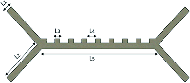
In this study, a single fluid chip design was made, and the input parameters of the system were changed. The design of the microfluidic chip was made with the SolidWorks program, as shown in Fig. 1. The microfluidic chip has two input channels and three output channels. Blood cells were sent at an absolute velocity through the inlet channels. Platelet and RBCs were separated from the output channels. All the dimensions of our microfluidic chip design are shown in Table 1.
| Parameter | Symbol | Value (μm) |
|---|---|---|
| Channel widths | L 1 | 25 |
| Inlet–outlet channel lengths | L 2 | 125 |
| Channel ledges length | L 3 | 25 |
| Length between ledges | L 4 | 30 |
| Middle channel length | L 5 | 300 |
| The thickness of the chip | t | 25 |
Analysis of microfluidics channel
In order to analyse the microfluidic chip, the design processes must be completed. In the previous section, the design process has been completed. After the design processes are realized, some parameters and definitions must be made to the system. The voltage that should be applied to the channels and the rate of blood entering the channel is significant for the separation processes of platelets and RBCs. These parameters are defined as variable input in analysis operations. In other words, it takes variable value in optimization processes with fuzzy logic.In this research, the designed microfluidic chip is loaded into the Comsol MultiPhysics program. Then the fixed parameters in the system are defined in the Comsol MultiPhysics program. In the system, some parameters are fixed, and some parameters are variable. Parameters such as blood values, blood cell sizes, frequency values are given as fixed in Table 2. The input and output parameters of the system are variable as optimization will be performed.
| Parameter | Value | Unit |
|---|---|---|
| Frequency of the electric field | 100 | kHz |
| Fluid relative permittivity | 80 | — |
| Fluid density | 1000 | kg m−3 |
| Fluid dynamic viscosity | 0.001 | Pa s |
| Platelets diameter | 2.1 | μm |
| RBCs diameter | 6 | μm |
| Platelet conductivity | 0.25 | S m−1 |
| RBCs conductivity | 0.31 | S m−1 |
The voltage given as an input to the microfluidic chip channel is given as in Fig. 2A. The voltage supplied to the system causes the DEP force to occur. This force provides the separation of blood cells. In order for blood cells to be successfully separated, one of the input channels must be at a constant velocity and the other channel must be variable. In experimental studies, the optimum constant velocity value was determined as 134 μm s−1. The velocities of blood delivered to the inlet channel of the microfluidic chip are shown in Fig. 2B. Here, the velocity in the first channel is constant and 134 μm s−1. The velocity in the second channel is defined as a variable. The velocity of this channel will affect the outputs in the system. In particular, it affects the velocity of blood cells, leaving the channel and the pressure that the blood effects on the channels.
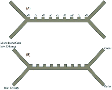 | ||
| Fig. 2 Microfluidic chip channel (A) location of the voltage input into the microfluidic chip channel (B) input velocities and outputs of blood cells in the microfluidic chip channel. | ||
Analysis of the microfluidic chip is required to perform optimization procedures. The problem of the system must be well understood in order to perform the analysis operations. For this reason, it is essential to determine the system's input and output parameters. Analysis will be carried out through these parameters. According to the results of the analysis, data related to the system will be obtained. Optimization will be done with the help of these data. In this study, hundreds of analysis processes were carried out in order to perform optimization processes. Since the input and output parameters in the system are not determined as a fixed number, the analysis process took much time.
Optimization of microfluidics
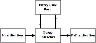
In the classical logic method, classifications are defined precisely. In other words, the member is either part of the group or not. It cannot be both at the same time. In short, the classical logic method has two values, 0 and 1. Contrary to this method, fuzzy logic can operate in complex conditions similar to the human mind-set. In the fuzzy logic method, the elements may be partially part of the fuzzy set. They can also belong to more than one cluster. In this method, uncertainties on the system can be expressed, and nonlinear functions can also be modelled.The essential elements of fuzzy logic are fuzzy inputs, outputs, rules, and blurring, as shown in Fig. 3. Fuzzy logic takes information from a standard language system and converts it into values. Values of input amounts associated with membership functions are given in the form of words such as fast, faster, slow, and slower. Then the input and output relationship is developed using rules. Outputs are obtained using the determined inputs and rules. Blurred outputs must be converted to real values so that they can be used in real systems.31–33
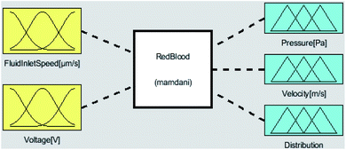
The first step to model a system using fuzzy logic is to identify its inputs and outputs. The most important task of a microfluidic is to separate the platelets in the chip channels. To achieve this, attention should be paid to the output parameters of fuzzy logic related to separation. In this study, optimization processes according to input and output parameters were done with Matlab-Fuzzy Logic. As the inputs of the system, the flow rate of the blood entering the chip system and the voltage given to the system are defined. The outputs of the system are defined as the velocity of the blood from the microfluidic channels, the separation of blood cells, and the pressure values of the blood cells that affect the channels. Voltage values allow the separation of RBCs and platelets. The inlet flow rate of the blood also affects the press of the blood cells acting on the microfluidic channels and the output rate of the blood cells in the microfluidic chip. The inputs and outputs of the fuzzy logic system are shown in Fig. 4.
Using fuzzy logic, blood flow rate, and voltage input parameters will help separate platelets from RBCs. Membership function values, upper and lower limits of the input, and output parameters are adjusted according to a specific problem. Hundreds of analysis processes were carried out with the Comsol MultiPhysics program. According to the analysis results, rules and parameter values were determined. After determining the upper and lower limits for modeling the required parameters with the membership function, a total of 16 rules were created to define the relationship between these parameters. To apply fuzzy logic to the microfluidic, logic rules must be created. This rule table is shown in Table 3.
| Inputs | Outputs | |||||
|---|---|---|---|---|---|---|
| FluidInlet speed | Voltage | Pressure | Velocity | Distribution | ||
| a LW = LOWEST, L = LOW, GD = GOOD, HG = HIGH, SGOB = SingleOutputBad, SPOG = SeparateOutputGood, SPOB = SeparateOutputBad. | ||||||
| 1 | LW | LW | THEN | LW | LW | SGOB |
| 2 | LW | L | THEN | LW | LW | SGOB |
| 3 | LW | GD | THEN | LW | LW | SPOG |
| 4 | LW | HG | THEN | LW | LW | SPOB |
| 5 | L | LW | THEN | LW | LW | SGOB |
| 6 | L | L | THEN | LW | LW | SGOB |
| 7 | L | GD | THEN | LW | LW | SPOG |
| 8 | L | HG | THEN | LW | LW | SPOB |
| 9 | GD | LW | THEN | GD | GD | SGOB |
| 10 | GD | L | THEN | GD | GD | SGOB |
| 11 | GD | GD | THEN | GD | GD | SPOG |
| 12 | GD | HG | THEN | GD | GD | SPOB |
| 13 | HG | LW | THEN | HG | HG | SGOB |
| 14 | HG | L | THEN | HG | HG | SGOB |
| 15 | HG | GD | THEN | HG | HG | SPOG |
| 16 | HG | HG | THEN | HG | HG | SPOB |
In the triangular membership function used for FluidInletVelocity input, ‘LOWEST’ for values in the range [0–500 μm s−1], ‘LOW’ for values in the range [500–800 μm s−1], ‘GOOD’ for values in the range of [800–1000 μm s−1], and ‘HIGH’ for values in the range [1000–1300 μm s−1] were used. In the triangle membership function used for voltage input, ‘LOWEST’ for values in the range of [0–2 V], ‘LOW’ for values in the range of [2–4 V], ‘GOOD’ for values in the range of [4–8 V], and ‘HIGH’ for values in the range of [8–12 V] were used. In the triangle membership function used for pressure output, ‘LOW’ for values in the range of [0–8 Pa], ‘GOOD’ for values in the range of [8–16 Pa], and ‘HIGH’ for values in the range of [16–24 Pa] were used. In the triangle membership function used for velocity output, ‘LOW’ for values in the range of [0–1 m s−1], ‘GOOD’ for values in the range of [1–2 m s−1], and ‘HIGH’ for values in the range of [2–3 m s−1] were used. In the triangular membership function used for distribution output, ‘SingleOutputBad’ for values in the range [0–2], ‘SeparateOutputGood’ for values in the range,2–4 and ‘SeperateOutputBad’ for values in the range4–6 were used.
Result and discussion
Comsol analysis results
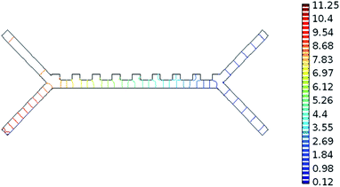
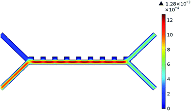
The system was analysed with the Comsol MultiPhysics program. Hundreds of analyses have been done to obtain optimum results of the system. The inputs of the system are defined as blood flow rate and voltage. The outputs are defined as pressure, velocity, and separation of blood cells. According to the results of the analysis, the optimum voltage to be given to the chip should be 4–6 V, and the velocity of the fluid should be between 800–900 μm s−1 in order to separate the RBCs and platelets. If the input parameters are applied to the microfluidic chip at these value ranges, it is understood that the pressure in the output channel is in the range of 10–12 Pa and the velocity in the range of 1.25–1.5 mm s−1.Pressure values in the microfluidic chip channels are given in Fig. 5. Paying attention to Fig. 5, the pressure at the inlet of the channels of the fluid chip will be higher. Pressure values towards the output of the chip will also decrease. Since the velocity at the inlet of the microfluidic chip is high, it affects the pressure, so the pressure in the inlet channels of the fluid chip is always higher. In the case of 5 V voltage to the microfluidic chip and the fluid velocity entering through the second channel is 825 μm s−1, the pressure values obtained from the outlet are as in Fig. 5. The maximum pressure acting along the channels is 11.25 Pa.
The velocity values in the microfluidic chip channels are given in Fig. 6. The velocity in the first channel of the microfluidic chip was taken as 134 μm s−1. This value is taken as a constant in all analyses in the system. If the flow velocity of the fluid in the second channel is also taken into consideration, it will be higher than the inlet velocity of the first channel. The velocity values towards the output of the chip will also generally decrease. If 5 V voltage is applied to the microfluidic chip and the fluid velocity entering through the second channel is 825 μm s−1, the velocity values obtained from the output are as in Fig. 6.
The separation of RBCs and platelets in the microfluidic chip channels is shown in Fig. 7A. In the case of 5 V voltage to the microfluidic chip, the fluid velocity entering from the first channel is 134 μm s−1, and the fluid velocity entering the second channel is 825 μm s−1, the RBCs and platelets are separated from each other as in Fig. 7A. As seen in Fig. 7A, RBCs are larger than platelets in size and come out from the bottom channel of the chip. Platelets, on the other hand, are smaller in size and come out of the upper channel of the chip. The most important factor affecting the separation of blood cells is the DEP force. The feature that causes this force to occur is the voltage supplied to the system. In the case of low voltage given to the system, blood cells cannot be separated from each other. In other words, all blood cells come from a single outlet, as in Fig. 7B.
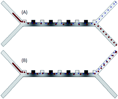 | ||
| Fig. 7 (A) Analysis results of the separation of blood cells in the channels of the microfluidic chip (B) blood cells in the channels of the microfluidic chip come out of a single channel. | ||
Fuzzy logic results
As a result of the analyses made with the Comsol MultiPhysics program, much data was obtained. These data are classified by the Matlab-Fuzzy Logic method and optimized. The input and output parameters required for this method are described in Section 2.3. The system is designed to have two inputs and three outputs in total. After determining the lower-upper values for each parameter with the membership function, a total of 16 rules were created to define the relationship between the parameters. The results of these rules determined by applying the Min-Max operator are shown as 3D graphics in Fig. 8. These figures show the relationship between input and output parameters.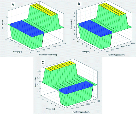 | ||
| Fig. 8 (A) FluidInletSpeed and voltage affects the velocity (B) FluidInletSpeed and voltages affects the pressure (C) FluidInletSpeed and voltages affects the distribution. | ||
As seen in Fig. 8A and B, FluidInletSpeed affects the velocity and pressure of the microfluidic in direct proportion. The effect of the voltage input value on the velocity and pressure of the microfluidic is less. After about 1000 μm s−1 FluidInletSpeed, velocity and pressure values increase significantly. While the maximum velocity acting along the channels is 1.85 mm s−1, the maximum pressure is determined as 16.89 Pa. Fig. 8C shows the result of the fuzzy logic model developed for separating red blood cells and platelets in the microfluidic chip channels. In this model, the effect of the voltage applied in the distribution process is high. The success rate in the distribution process increases after the 4 V voltage value. The change in FluidInletSpeed is less effective. In case of low voltage given to the system, blood cells cannot be separated. Table 4 describes the variation in the output parameters in response to the given inputs of the microfluidic channel.
| Input | Output | |||
|---|---|---|---|---|
| FluidInletSpeed [μm s−1] | Voltage [V] | Pressure [Pa] | Velocity [m s−1] | Distribution |
| 300 | 1 | 4 | 0.5 | SingleOutputBad |
| 300 | 3 | 4 | 0.5 | SingleOutputBad |
| 300 | 6 | 4 | 0.5 | SeparateOutputGood |
| 600 | 1 | 4 | 0.5 | SingleOutputBad |
| 600 | 3 | 4 | 0.5 | SingleOutputBad |
| 600 | 10 | 4 | 0.5 | SeparateOutputBad |
| 900 | 1 | 12 | 1.5 | SingleOutputBad |
| 900 | 3 | 12 | 1.5 | SingleOutputBad |
| 900 | 6 | 12 | 1.5 | SeparateOutputGood |
| 1200 | 1 | 20 | 2.5 | SingleOutputBad |
| 1200 | 3 | 20 | 2.5 | SingleOutputBad |
| 1200 | 10 | 20 | 2.5 | SeparateOutputBad |
Conclusions
In this study, a microfluidic chip was designed and analysed with the Comsol MultiPhysics program in order to perform the separation of platelets from RBCs. The data obtained as a result of the analyses were classified in the Matlab-Fuzzy Logic program, and optimization processes were carried out. The data obtained during the optimization processes were obtained by changing the input parameters. Output data were obtained by changing input parameters over the same design.As a result of the analysis and optimization processes, the optimum voltage that should be given to the chip in order to separate the platelet cells from the RBCs should be 4–6 V, and the velocity of the fluid should be between 800–900 μm s−1. If the input parameters are applied to the microfluidic chip at these value ranges, it is understood that the pressure in the output channel is in the range of 10–12 Pa and the velocity in the range of 1.25–1.5 mm s−1.
Since this study is also possible to control in real-time, it provides the infrastructure for the production of devices related to the biomedical fields of separation of blood cells depending on the variables in the microfluidic chip. In our next study, the effect on separation of platelets from red blood cells will be investigated by designing different sized micro channels. As a result of these investigates, the microfluidic chip will be fabricated in the most appropriate design.
Conflicts of interest
There are no conflicts to declare.References
- R. W. Colman, Hemostasis and Thrombosis: Basic Principles and Clinical Practice, Lippincott Williams & Wilkins, 2006 Search PubMed.
- S. Kattula, J. R. Byrnes and A. S. Wolberg, Fibrinogen and Fibrin in Hemostasis and Thrombosis, Arterioscl. Throm. Vas., 2017, 37, 13–21 CrossRef.
- M. S. Pommer, Y. Zhang, N. Keerthi, D. Chen, J. A. Thomson, C. D. Meinhart and H. T. Soh, Dielectrophoretic Separation of Platelets from Diluted Whole Blood in Microfluidic Channels, Electrophoresis, 2008, 29, 1213–1218 CrossRef CAS PubMed.
- A. J. Magill, E. T. Ryan, D. R. Hill and T. Solomon, Hunter's Tropical Medicine and Emerging Infectious Disease: Expert Consult-Online and Print, Elsevier Health Sciences, 2012 Search PubMed.
- Y. Englert, B. Lesage, J. P. Van Vooren, C. Liesnard, I. Place, A. S. Vannin and A. Delbaere, Medically Assisted Reproduction in the Presence of Chronic Viral Diseases, Hum. Reprod. Update, 2004, 10, 149–162 CrossRef.
- T. C. Quinn, D. Classer, R. O. Cannon, D. L. Matuszak, R. W. Dunning, R. L. Kline and E. W. Hook III, Human immunodeficiency virus infection among patients attending clinics for sexually transmitted diseases, N. Engl. J. Med., 1998, 318, 197–203 CrossRef.
- P. L. Perrotta, P. T. Pisciotto, E. L. Snyder, C. D. Hillyer, L. E. Silberstein, P. M. Ness, K. C. Anderson and K. S. Roush, Blood Banking and Transfusion Medicine: Basic Principles and Practice, Churchill Livingstone/Elsevier, 2003 Search PubMed.
- J. Tian, L. H. H. Cheng, X. Cui, X. X. Lei, J. B. Tang and B. Cheng, Application of Standardized Platelet-Rich Plasma in Elderly Patients with Complex Wounds, Wound Repair Regen., 2019, 27, 268–276 CrossRef PubMed.
- M. Suthar, S. Gupta, S. Bukhari and V. Ponemone, Treatment of Chronic Non-Healing Ulcers Using Autologous Platelet Rich Plasma: a Case Series, J. Biomed. Sci., 2019, 24, 16 CrossRef.
- A. W. Anz, R. S. Parsa, M. F. Romero-Creel, A. Nabors, M. S. Tucker, R. M. Harrison and A. M. Matuska, Exercise-Mobilized Platelet-Rich Plasma: Short-Term Exercise Increases Stem Cell and Platelet Concentrations in Platelet-Rich Plasma, Arthroscopy, 2019, 35, 192–200 CrossRef.
- K. Kikkeri, B. A. Kerr, A. S. Bertke, J. S. Strobl and M. Agah, Passivated-Electrode Insulator-Based Dielectrophoretic Separation of Heterogeneous Cell Mixtures, J. Sep. Sci., 2020, 43, 1576–1585 CrossRef CAS.
- V. Shkkov, D. Xin and C. H. Chen, Continuous Dielectrophoretic Particle Separation via Isomotive Dielectrophoresis with Bifurcating Stagnation Flow, Electrophoresis, 2019, 40, 2988–2995 CrossRef.
- R. S. Thomas, P. D. Mitchell, R. O. C. Oreffo, H. Morgan and N. G. Green, Image-Based Sorting and Negative Dielectrophoresis for High Purity Cell and Particle Separation, Electrophoresis, 2019, 40, 2718–2727 CrossRef CAS.
- N. V. Nguyen and C. P. Jen, Impedance Detection Integrated with Dielectrophoresis Enrichment Platform for Lung Circulating Tumor Cells in a Microfluidic Channel, Biosens. Bioelectron., 2018, 121, 10–18 CrossRef CAS PubMed.
- K. Zhao and D. Li, Tunable Droplet Manipulation and Characterization by AC-DEP, ACS Appl. Mater. Interfaces, 2018, 10, 36572–36581 CrossRef CAS.
- H. Maechi Ethad, R. K. Yadav, S. Guha and C. Wenger, Towards CMOS Integrated Microfluidics Using Dielectrophoretic Immobilization, Biosensors, 2019, 9, 77 CrossRef PubMed.
- Y. Jia-Fen, J. Zhu-Peng, Z. Tong, W. Hao, C. Bai and W. Hong-Tao, Analysis of Cell Dielectrophoretic Motion with Microfluidic Device Embedding Multi-electrodes, Chin. J. Anal. Chem., 2019, 47, 221–228 Search PubMed.
- L. Chen, G. Luo, K. Liu, J. Ma, B. Yao, Y. Yan and Y. Wang, Bonding of Glass-Based Microfluidic Chips at Low-or Room-Temperature in Routine Laboratory, Sens. Actuators, B, 2006, 119, 335–344 CrossRef CAS.
- F. Yu, D. Nivasini, O. S. Kumar, D. Choudhury, L. C. Foo and S. H. Ng, Microfluidic Platforms for Modeling Biological Barriers in the Circulatory System, Drug Discovery Today, 2018, 23, 815–829 CrossRef CAS.
- T. A. Crowley and V. Pizziconi, Isolation of Plasma from Whole Blood Using Planar Microfilter for Lab-on-a-Chip Applications, Lab-on-a-Chip, 2005, 5, 922–929 RSC.
- R. L. Chien and W. J. Parce, Multiport Flow-Control System for Lab-on-a-Chip Microfluidic Devices, Springer, 2001, 371, 106–111 CAS.
- L. Chen, S. Lee, M. Lee, C. Lim, J. Choo, J. Y. Park and Y. W. Choi, DNA Hybridization Detection in a Microfluidic Channel Using Two Fluorescently Labelled Nucleic Acid Probes, Biosens. Bioelectron., 2008, 23, 1878–1882 CrossRef CAS PubMed.
- J. Zhang, D. Yuan, Q. Zhao, S. Yan, S. Y. Tang, S. H. Tan and W. Li, Tunable Particle Separation in a Hybrid Dielectrophoresis (DEP)-Inertial Microfluidic Device, Sens. Actuators, B, 2018, 267, 14–25 CrossRef CAS.
- N. V. Nguyen and C. P. Jen, Impedance Detection Integrated with Dielectrophoresis Enrichment Platform for Lung Circulating Tumor Cells in a Microfluidic Channel, Biosens. Bioelectron., 2018, 121, 10–18 CrossRef CAS PubMed.
- A. M. Brooks, M. Tasinkevych, S. Sabrina, D. Velegol, A. Sen and K. J. Bishop, Shape-Directed Rotation of Homogeneous Micromotors via Catalytic Self-Electrophoresis, Nat. Commun., 2019, 10, 1–9 CrossRef PubMed.
- K. Dastani, M. Moghimi Zand and A. Hadi, Dielectrophoretic Effect of Nonuniform Electric Fields on the Protoplast Cell, Journal of Computational Applied Mechanics, 2017, 48, 1–14 Search PubMed.
- R. C. Gallo-Villanueva, V. H. Perez-Gonzalez, B. Cardenas-Benitez, B. Jind, S. O. Martinez-Chapa and B. H. Lapizco-Encinas, Joule Heating Effects in Optimized Insulator-Based Dielectrophoretic Devices: An Interplay Between Post Geometry and Temperature Rise, Electrophoresis, 2019, 40, 1408–1416 CrossRef CAS PubMed.
- A. Y. Jiang, A. R. Yale, M. Aghaamoo, D. H. Lee, A. P. Lee, T. N. Adams and L. A. Flanagan, High-Throughput Continuous Dielectrophoretic Separation of Neural Stem Cells, Biomicrofluidics, 2019, 13, 064111 CrossRef.
- M. Lorenz, D. Malangré, F. Du, M. Baune, J. Thöming and G. R. Pesch, High-Throughput Dielectrophoretic Filtration of Sub-micron and Micro Particles in Macroscopic Porous Materials, Anal. Bioanal. Chem., 2020, 1–12 Search PubMed.
- A. Kale, L. Song, X. Lu, L. Yu, G. Hu and X. Xuan, Electrothermal Enrichment of Submicron Particles in an Insulator-Based Dielectrophoretic Microdevice, Electrophoresis, 2018, 39, 887–896 CrossRef CAS.
- C. Caraveo, F. Valdez and O. Castillo, Optimization of Fuzzy Controller Design Using a New Bee Colony Algorithm with Fuzzy Dynamic Parameter Adaptation, Appl. Soft Comput., 2016, 43, 131–142 CrossRef.
- S. Farajdadian and S. H. Hosseini, Optimization of Fuzzy-Based MPPT Controller via Metaheuristic Techniques for Stand-Alone PV Systems, Int. J. Hydrogen Energy, 2019, 44, 25457–25472 CrossRef CAS.
- M. A. Kacimi, O. Guenounou, L. Brikh, F. Yahiaoui and N. Hadid, New Mixed-Coding PSO Algorithm for a Self-Adaptive and Automatic Learning of Mamdani Fuzzy Rules, Eng. Appl. Artif. Intel., 2020, 89, 103417 CrossRef.
| This journal is © The Royal Society of Chemistry 2020 |

