DOI:
10.1039/C7SM01596H
(Paper)
Soft Matter, 2017,
13, 8858-8863
Frame, metric and geodesic evolution in shape-changing nematic shells
Received
8th August 2017
, Accepted 6th November 2017
First published on 16th November 2017
Abstract
Non-uniform director fields in flat, responsive, glassy nematic sheets lead to the induction of shells with non-trivial topography on the application of light or heat. Contraction along the director causes metric change, with, in general, the induction of Gaussian curvature, that drives the topography change. We describe the metric change, the evolution of the director field, and the transformation of reference state material curves, e.g. spirals into radii, as curvature develops. The non-isometric deformations associated with heat or light change the geodesics of the surface, intriguingly even in regions where no Gaussian curvature results.
1 Introduction
Nematic solids elongate or contract along their preferred direction, the director n, in response to heat, light, pH change, and solvent uptake. In the two directions perpendicular to n there is an attendant contraction or elongation, either conserving volume (elastomers) or not (glasses), except where the driver is solvent exchange (elastomers) where there must be volume change.
Although deformations are simple locally, if the director field n(r) is non-uniform in the plane of a sheet-like sample, it will in general be driven to develop Gaussian curvature (GC) to avoid expensive distortion from the new, natural contracted/elongated state. There is a strong motive to have non-uniform fields and thus switchable Gaussian Curvature, since such systems offer new forms of strong actuation where blocking evolution to the new natural state allows one to harness the attendant stretches; see for instance Ware et al.1
The induced Gaussian curvature can be specified in terms of the new metric tensor, a = UT·U (with U the deformation gradient to a new relaxed state arising from the stimulations listed above). The metric specifies the changed intrinsic lengths in the surface and the GC can be expressed in terms of the spatial variation of a, that is, through the connection coefficients Γ.
The local thermo-optical deformation gradients are simple and based on n
where
m is the direction in-plane that is perpendicular to
n, that is, the in-plane orthogonal dual of
n. There is a contraction
λ < 1 along
n and elongation of
λ−ν along
m. The constant

has been termed the opto-thermal Poisson ratio
2 in analogy with the conventional Poisson ratio; it determines the response perpendicular to a deformation induced along
n.
The in-plane pattern for n(r) and m(r) is set at the time of sample preparation. It can evolve under the action of U: where n is non-uniform, there may additionally be local rotations R(r) in order that the total deformation F = R·U remains locally and globally compatible, assuming that the surface that evolves is embeddable and smooth etc. The local rotations of the material convect n and m to new values that constitute a new, diagonal frame on which to base the next deformation and subsequent further rotation. The metric induced is of course unchanged by the rotations: a = FT·F = UT·RT·R·U = UT·U.
We investigate 3 critical aspects of these non-uniform deformations:
(1) The metric of the space evolves as λ changes. After every increment of λ and hence of a, should subsequent development use the incremented a, or can one jump directly to a finite deformation λ, and simply take the metric that corresponds to that Fλ? We find that one can – the metric is not “dragged”. Equally, we will show that the rotations induced can be simply compounded, even when the λs are large. We show this property by a general argument based on a pair of successive finite deformations.
(2) In circularly symmetric systems of general theoretical and experimental interest, it is clear that there are deformation-induced rotations of material directions, but that circles centred at the origin must transform into circles. We offer an explicit geometric construction that resolves these two apparently contradictory aspects, and recover expressions for the rotations involved and for the inflation of the intrinsic circles that define the system. We show how certain general curves, proto-radii, become geodesic radii on distortion. We further put conditions on the director field that is needed to generate only shells of revolution, and thereby give a criterion for when circular symmetry breaks down.
(3) We consider geodesics on cones that result from the response of circular, radial or, in general, logarithmic spiral director distributions. They are different from those of cones that are more conventionally constructed from flat sheets. The former are the products of non-isometric transformations. The curves in the flat space that are geodesics in the target space differ, even though both types of cones have zero Gaussian curvature, except at their tips.
2 Metric evolution and the compounding of their intermediate states
We consider the evolution of the induced metric upon heating of a sheet-like nematic sample with director field n(r). The heating of the sample manifests as a gradually decreasing λ < 1, indicating further contractions along the director. As the system evolves, both n and m can locally rotate with respect to material lines across the surface of the sample. We analyse this evolution by discretising it into a 2-step process: an initial deformation Φλ1 corresponding to a contraction by λ1 along n and mapping an initial surface Σ0 onto an intermediate surface Σ1, followed by a second deformation Φλ/λ1 corresponding to a contraction by λ/λ1 along the new evolved director field which maps Σ1 onto a final surface Σ2, as depicted in Fig. 1.
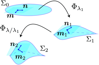 |
| | Fig. 1 Compatibility of local deformations. The director field n and its in-plane orthogonal dual m remain orthogonal throughout the evolution as they locally rotate with respect to material lines across the surface. Finite deformations compound as expected. | |
Consider a mesh of curves ![[capital script C]](https://www.rsc.org/images/entities/char_e522.gif) 1 and
1 and ![[capital script C]](https://www.rsc.org/images/entities/char_e522.gif) 2 on a surface, initially planar. In calculations of surface evolution, especially of circular symmetry, these might typically be circles and either radii or radially advancing spirals. One derives from these curves the corresponding family of tangents t1 and t2. In the above examples mentioned, they are (ṙ1,
2 on a surface, initially planar. In calculations of surface evolution, especially of circular symmetry, these might typically be circles and either radii or radially advancing spirals. One derives from these curves the corresponding family of tangents t1 and t2. In the above examples mentioned, they are (ṙ1,![[small theta, Greek, dot above]](https://www.rsc.org/images/entities/i_char_e0a7.gif) 1) with ṙ1 = 0 for circles (where · = d/ds and s is a unit speed parametrisation), and (ṙ2,
1) with ṙ1 = 0 for circles (where · = d/ds and s is a unit speed parametrisation), and (ṙ2,![[small theta, Greek, dot above]](https://www.rsc.org/images/entities/i_char_e0a7.gif) 2) – the tangent to a spiral curve of interest, for instance to a proto-radius. The original tangents, ti, transform into new ones,
2) – the tangent to a spiral curve of interest, for instance to a proto-radius. The original tangents, ti, transform into new ones, ![[t with combining tilde]](https://www.rsc.org/images/entities/b_i_char_0074_0303.gif) i, for i = 1, 2, as
i, for i = 1, 2, as
| | Fλ1·ti ≡ Rλ1·Uλ1·ti ≡ ![[t with combining tilde]](https://www.rsc.org/images/entities/b_i_char_0074_0303.gif) i i | (2) |
where the rotation
Rλ1 is with respect to the given collection of frames on the evolving surfaces.
Rλ1 is induced by the deformation and its action on
n gives
ñ =
Rλ1·
n. Both
R and
n depend on
r, and likewise
![[m with combining tilde]](https://www.rsc.org/images/entities/b_i_char_006d_0303.gif)
=
Rλ1·
m. We will see below the total deformation naturally broken down (its polar decomposition) into a
Rλ1·
Uλ1 since
Uλ1 is delivered diagonal in its
n,
m frame. The rotation we determine below convects
n and
m and provides us with a new frame where, by construction, the subsequent
U is diagonal.
This subsequent deformation Uλ/λ1(ñ) now occurs, by a further factor λ/λ1 which is along the current director ñ rather than the original n. The current mesh  will further deform. We will need, for instance, directional relationships between further deformed meshes using the metric
  resulting from the further deformation λ/λ1 along the current director ñ:
| | ![[t with combining tilde]](https://www.rsc.org/images/entities/b_i_char_0074_0303.gif) T2·aλ/λ1(ñ)· T2·aλ/λ1(ñ)·![[t with combining tilde]](https://www.rsc.org/images/entities/b_i_char_0074_0303.gif) 1. 1. | (3) |
For instance if
(3) = 0, then the initial mesh of curves
![[capital script C]](https://www.rsc.org/images/entities/char_e522.gif) 1
1 and
![[capital script C]](https://www.rsc.org/images/entities/char_e522.gif) 2
2 have evolved under two, compounded deformations into normal coordinates. We need to be reassured, here by explicit construction, that the evolution of the metric, so central to these calculations, is being correctly accounted for during successive deformations where it too is evolving.
One can re-write eqn (3):
| |  | (4) |
Now one can see how the intermediate state after deformation
λ1 is immaterial:

and
Rλ1 act (forward and backward respectively) on the
ñ and
![[m with combining tilde]](https://www.rsc.org/images/entities/b_i_char_006d_0303.gif)
to restore them to
n and
m respectively. Recall that
Fλ1 is based on
n and
m, as is now the central part of
eqn (4) since it has become (
λ/
λ1)
2n ⊗
n+ (
λ/
λ1)
−2νm ⊗
m. Then the
F and
FT can be contracted with the central part to give (
λ2n ⊗
n +
λ−2νm ⊗
m) ≡
aλ(
n), with the result
We have thus shown that, although the metric evolves as the directors are convected by deformations, it is sufficient to consider even a non-linear deformation to be in terms of the initial state and the metric appropriate to any large deformations based on the initial state. That is, the frame is “dragged” but not to any fundamental effect. Conversely, the compounding of infinitesimal deformations and rotations to give, say, the compounding of two large deformations rules out any higher order differential effects in the metric evolution.
It should be noted that a global deformation map Φ: Σi → Σf, from an initial surface Σi to a final surface Σf, carries by contrast much more information than is provided by the metric formalism and isometric embedding approach taken in Mostajeran,3 for instance. An analysis based purely on the metric formalism typically yields the surface that is formed following the stimulation of a given director field by solving an isometric embedding problem based on the induced metric, but it does not specify where individual points from the initial surface end up on the final surface. Generally, it is difficult to determine such a global deformation even when the final surface has been identified. However, in Section 3 we provide a detailed picture of the movement of individual points during the course of the deformation for the important class of circularly symmetric director patterns, which typically result in surfaces of revolution. One needs to consider trajectories and their length changes, as in ref. 5. We use such methods to give a prescription in Section 5 for when a circularly symmetric director field n(r) will give a surface of revolution, rather than a ruffled surface.
3 Circular symmetry and the rotations attendant on deformations
Circularly symmetric director patterns, generically spirals, generate deformations based on local frames of n and m. The director fields themselves will evolve, which we now examine, unless they were the special cases of radii and circumferences. By symmetry, deformations must take circles to circles, albeit in general inflated or deflated. At a point (r,θ) the director has an angle α(r) with the radial direction, ![[r with combining circumflex]](https://www.rsc.org/images/entities/b_i_char_0072_0302.gif) ; see Fig. 2(a). This angle varies with radius except for the special case of logarithmic spirals of n, where α = constant and nematic contractions yield simple cones.2,4
; see Fig. 2(a). This angle varies with radius except for the special case of logarithmic spirals of n, where α = constant and nematic contractions yield simple cones.2,4
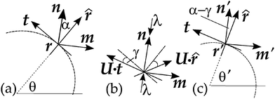 |
| | Fig. 2 (a) A section of a circle (dotted) in the initial (flat) space before distortion, showing its tangent t. The director n(r) is at angle α(r) to the radial direction, ![[r with combining circumflex]](https://www.rsc.org/images/entities/b_i_char_0072_0302.gif) . (b) A contraction by a factor λ along n rotates (and distorts) general vectors, e.g.t and . (b) A contraction by a factor λ along n rotates (and distorts) general vectors, e.g.t and ![[r with combining circumflex]](https://www.rsc.org/images/entities/b_i_char_0072_0302.gif) , towards the perpendicular m. For instance, the tangent t was rotated through angle γ. (c) By symmetry, circles must transform overall into circles (here shown as deflated). Through a rotation R−γ by −γ, the vector Fλ·t is restored to tangency and the director, n', is now at angle α − γ to the radial direction. In general, material points r rotate to a new angle , towards the perpendicular m. For instance, the tangent t was rotated through angle γ. (c) By symmetry, circles must transform overall into circles (here shown as deflated). Through a rotation R−γ by −γ, the vector Fλ·t is restored to tangency and the director, n', is now at angle α − γ to the radial direction. In general, material points r rotate to a new angle  . In the text we delay discussing the extra rotation, and mark the restored tangent simply as t. . In the text we delay discussing the extra rotation, and mark the restored tangent simply as t. | |
Consider, Fig. 2(b), in a frame based on n and m, depicting a contraction by λ along n. It fans out away from n the in-material vectors t and ![[r with combining circumflex]](https://www.rsc.org/images/entities/b_i_char_0072_0302.gif) to Uλ·t and Uλ·
to Uλ·t and Uλ·![[r with combining circumflex]](https://www.rsc.org/images/entities/b_i_char_0072_0302.gif) (no longer unit vectors); the angle γ between Uλ·t and t is defined in the figure. Thus
(no longer unit vectors); the angle γ between Uλ·t and t is defined in the figure. Thus
with
p the degree of circumferential deflation/inflation, and
Rγ a rotation by
γ. Since points on circles remain on circles, then clearly the action from neighbouring points gives a local angular convection to restore
Uλ·
t to tangency, in general along with a rotation of the circle as a whole, so the point at
θ evolves to
θ′; see
Fig. 2(c). The next section gives explicit forms for
θ′ −
θ by considering how special curves (“proto-radii”) in the reference state evolve to be actual radii in the target state.
The angle between Uλ·t and n became π/2 − α + γ after deformation. As Uλ·t (with all other in-material vectors) is rotated by −γ to make it again a tangent (with rescaling to restore it to being a unit vector), then the current director n′ is now at an angle α − γ to the new radial direction. Note that this latter, radial direction was not originally so, but evolved from its pre-image (the proto radius) to be a radius.
Expanding out eqn (6) in the original frame to get the fanning out, one has:
| | | λ(n(r)·t)n + λ−ν(m(r)·t)m = pRγ·t. | (7) |
The projections of t onto n and m were respectively sα and −cα (with s ≡ sin, c ≡ cos). Multiplying both sides by R−γ, the vectors n and m become n′ = R−γ·n and m′ = R−γ·m; see Fig. 2(c), but for the moment delay considering the rotation by θ′ − θ so the restored tangent in Fig. 2(c) is denoted by the original t:
Contracting this equation with the unit tangent
t and with the unit radial vectors gives respectively:
| | | λsαsα−γ + λ−νcαcα−γ = p | (9) |
| | | λsαcα−γ − λ−νcαsα−γ = 0. | (10) |
The latter relation gives the new director angle, which can be injected into the former expression for
p(
r) to give the inflation. In summary
or
| | cot![[thin space (1/6-em)]](https://www.rsc.org/images/entities/char_2009.gif) γ = (b2 + λ+ν)/(b(1 − λ1+ν)) γ = (b2 + λ+ν)/(b(1 − λ1+ν)) | (12) |
| |  | (13) |
where
b = cot
![[thin space (1/6-em)]](https://www.rsc.org/images/entities/char_2009.gif) α
α. The inflation depends on radius according to the initial director angle
α(
r) to the radial direction, and depends on the deformation. Of special interest is the location of
r1(
λ) where
p = 1, for there the circumference is unchanging and the evolved shell can be anchored to an unchanging circumferential support without strain-mismatch. At that condition, one has

which can be solved then for
r1(
λ). This result shows that the anchoring condition (3.16) of Mostajeran
et al.5 is completely general and not simply for logarithmic spiral systems.
Rotations can be seen explicitly to compound, as they do via metric considerations:
| | 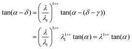 | (14) |
where
λ1 takes the system from
α →
α − (
δ −
γ), and then
λ/
λ1 from
α − (
δ −
γ) to
α −
δ, that is a further
γ. Intermediate steps,
λ1 with angular advancement (
δ −
γ), are seen to be inessential.
4 Evolution of director field integral curves and of proto-radii
The integral curve of the director field has as its tangent the director itself. For the simple illustration taken, cones, the tangent has a constant angle, α, to the radial direction. The integral curve is thus a logarithmic spiral| | r(θ) = r0eb(θ−θ0) with b = cot![[thin space (1/6-em)]](https://www.rsc.org/images/entities/char_2009.gif) α. α. | (15) |
This angle was reduced to α − γ with tan(α − γ) given by eqn (11). Since α here is independent of r, then so is γ and thus the new director integral curve is also a log spiral, now with a b′ = cot(α − γ) = b/λ1+ν, a more rapidly outward spiralling curve.
One can similarly determine the curve, Γ2, of the reference state proto-radius that will become the target space radius, Γ2′, the line that meets circles at right angles. Take a reference state circle to be Γ1, and its image after the action of F to be the in/deflated circle Γ1′. The meeting at right angles in the target space gives the reference state condition3,5
where
t1 = (0,1) and
t2 = (d
r2/d
s,d
θ2/d
s) are the tangents, in circular coordinates, to
Γ1 and
Γ2. They have a unit speed parametrisation by
s. In circular coordinates
a is:
| | 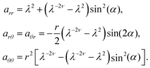 | (17) |
[The last component of
a governs azimuthal changes and taken as
aθθ/
r2 gives the square of the inflation,
p2(
r).] The condition
(16) reduces to (dropping the subscript 2):
| |  | (18) |
The argument thus far is completely general for any
α(
r). For the log spiral case,
α = constant, integration is trivial:
The proto-radius is a log spiral characterised by
| |  | (20) |
with
β the angle the tangent makes with the radius before deformation. One can easily show that
c ≠
b, that is, the integral curves of director and proto-radius differ.
These curves are illustrated in Fig. 3. The extent of bulk rotation is now clear: points on the proto-radius Γ2 rotate through an angle  to be on the radius Γ2′ after distortion. The rotation is the sum of the rotations that occur at each element r′ inside the current radius.
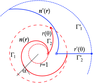 |
| | Fig. 3 The original log spiral director n(r) (red online) of constant angle α = 1.4 rad, on a deformation of λ = 0.7 with ν = 2, transforms to the new director field n′(r) (blue online), also log spirals, but with larger angle. The original α angle between the tangent to the director's integral curve tangent and a radius is shown as α (black). Transformed curves are shown in-material but on the same diagram for convenience. The initial field is shown for r(θ = 0) = 1 to an r(θ = 2π) = e2πb, that is for one revolution of the spiral, between the light dotted unit circle and the heavy dotted circle, the reference space trajectory Γ1. The proto-radius Γ2 is the integral curve r(θ) that becomes an actual radius Γ2′, marked r′(θ). It started at r = 1 (open dot), but due to radial inflation starts further out (open dot). The proto-radius' end point (full dot) where it meets Γ1 transforms to the end point of Γ2′ (full dot) where it meets the transformed circle Γ1′. | |
5 Condition on α(r) for circularly symmetric shells
A circularly symmetric director field does not necessarily lead to a circularly symmetric shell on distortion. For instance a purely radial field subjected to heating develops in-material radii that become shorter and circumferences longer such that their ratio is greater than 2π: ruffles develop that have been termed “anti-cones”.2 In general, spirals with an α(r) can also develop in-material radii that are too short in comparison to the circumferences that arise, leading to loss of circular symmetry. Consider Fig. 4 where clearly 2πl1 > l2 and ruffles have not arisen. However, the condition for the preservation of circular symmetry is local, namely that the increments in the shell in considering what corresponds to  in the reference state must satisfy dl2 < 2πdl1, which is the case in the figure. The case of dl2 = 2πdl1 would correspond to the addition to dl1 being flat, and dl2 > 2πdl1 would mean that surplus circumference is generated and can only be accommodated by ruffling, that is by a loss of circular symmetry.
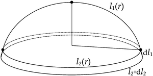 |
| | Fig. 4 A circularly symmetric shell with an in-material radius of length l1(r) extending from the pole (dot) to the current shell edge (dot), where the circumference is l2(r). Recall that the current radius has evolved from a pre-image (proto-radius) in the reference state extending from the centre of a spiral director field out to an r. An addition dl1 to the in-material radius leads to an increased circumference l2 + dl2. | |
The proto-radius that evolves to the in-material radius of length l1(r) is governed by eqn (16) and (18). For this curve it is shown5 that  . A circumference at r in/deflates to 2π
  . The latter result is elementary since we are dealing with length changes in the θ-direction. Taking its derivative and taking the above condition for circular symmetry one obtains:
| |  | (21) |
One can immediately recover the condition
4 separating cones and anti-cones for log spirals
n(
r) where
α = const., and also recover the condition on the tuning parameter
c for the
α(
r) generating spherical spindles and hyperbolic cones.
5 For instance, for a constant
K > 0 the director field
| |  | (22) |
introduced in
ref. 5 defines a spiral nematic pattern which encodes constant Gaussian curvature
K > 0 on the domain on which
(22) is defined. The parameter
c is a tuning parameter that can be used to adjust the radius on which the pattern is defined. The metric component
aθθ for the director field
(22) takes the form
| |  | (23) |
and upon substitution into
(21) yields
| | | λ2−2νKr2 + 2λ1−ν − λ−2ν − λ2 − c(λ−2ν − λ2) > 0, | (24) |
which must be satisfied for all values of
r > 0 in the domain of
α(
r) to result in a surface of revolution. This is clearly the case if and only if
(24) is satisfied at
r = 0. That is, precisely if
| |  | (25) |
which is in agreement with the condition
5 on
c for a spherical spindle of constant positive curvature
K to result from the director field specified by
(22).
6 Evolution of geodesics
Considering how points on a nematic surface move as the surface evolves under heating leads to an interesting observation concerning geodesics on the surface. Specifically, that material lines that form geodesics on an initial surface will generally not remain geodesics as the surface evolves. This is certainly to be expected when the induced metric is non-Euclidean, since in such cases the intrinsic geometry of the resulting surface is different. The more remarkable result is that a geodesic material line may not remain a geodesic under evolution even in cases where the induced metric is flat, i.e. does not generate Gaussian curvature.
We highlight this feature through a simple example involving the formation of cones from an initially flat surface by 2 different methods. In the first method, we simply cut out a sector from a circular disc and join the new edges of the remaining surface to form a cone by bending, as shown in Fig. 5. This is possible since a cone has zero Gaussian curvature at every point except for its tip, and thus away from this singular point has the same intrinsic geometry (Euclidean) as the plane by Minding's theorem. In this method, geodesics in the initially flat disc will map onto geodesics on the resulting cone. The second method is based on heating an initially flat nematic disc patterned by an azimuthal director field, which will form a cone with opening angle ϕ = sin−1(λ1+ν) as explained in ref. 4.
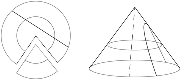 |
| | Fig. 5 Forming a cone by bending a flat circular disc with a missing sector. Straight lines on the disc map to geodesics on the cone. | |
Now for a given metric ds2 = aαβdxαdxβ, the geodesics satisfy the Euler–Lagrange equations of the functional
| |  | (26) |
For the standard Euclidean metric d
s2 = d
x2 + d
y2 = d
r2 +
r2d
θ2, the Euler–Lagrange equations in polar coordinates are
| |  | (27) |
| |  | (28) |
where
C is a constant. Thus, the straight line geodesics in polar coordinates arise as solutions to the system
| |  | (29) |
On heating the azimuthal pattern, the induced metric becomes d
s2 =
λ−2νd
r2 +
λ2r2d
θ2 and the Lagrangian in
(26) is modified to
L(
r,
θ,
ṙ,
![[small theta, Greek, dot above]](https://www.rsc.org/images/entities/i_char_e0a7.gif)
) =
λ−2νṙ2 +
λ2r2![[small theta, Greek, dot above]](https://www.rsc.org/images/entities/i_char_e0a7.gif) 2
2. The geodesic equations now take the form
| |  | (30) |
The solutions to this system are curves on the initial disc that become geodesics on the resulting cone. Clearly, we see that the systems in
(29) and
(30) are distinct and generally give rise to different solutions unless
C = 0. That is, straight lines on the flat disc will generally not map onto geodesics on the resulting cone, even where no Gaussian curvature is induced in the process. Indeed we have also seen, in the log spiral variant of the evolution to cones, that a resultant geodesic in the form of a radial line originates as a log spiral in the reference state which is definitely not an initial geodesic.
7 Discussion
The evolution of the shape of a nematic surface upon stimulation is governed by the metric induced by local deformations encoded by the director field. The stimulation of the sample is not instantaneous, but is achieved through a continuous process such as heating, during which the surface undergoes a continuous family of deformations. The director field itself also evolves during this process and undergoes local rotations with respect to material lines across the evolving surface. Due to the anisotropic nature of nematic surfaces, the question of compatibility of infinitesimal deformations within the metric framework is a non-trivial one that needs to be considered. In this work, we have addressed this concern and demonstrated that the evolution of the surface and director field is indeed consistent with such a framework. It should be noted that this issue does not arise for materials which undergo local expansion/contraction in a conformal or isothermal manner in response to stimulus, such as responsive hydrogels,6 since there is no potential “frame-dragging” effect in such materials. Furthermore, while it is possible to express a metric associated with a nematic director field in isothermal form through a suitable change of coordinates,7 the necessary coordinate transformation is dependent on λ and hence is not valid throughout the evolution. By considering the local rotations of the director field during the evolution of the deformation of a nematic surface, we also obtain a description of how individual material points move on the evolving surface for the class of circularly symmetric director fields which form surfaces of revolution.
Conflicts of interest
There are no conflicts of interest to declare.
Acknowledgements
C. Mostajeran received funding from the Engineering and Physical Sciences Research Council (EPSRC) of the United Kingdom during the preparation of this work. C. D. Modes gratefully acknowledges funding from the Max Planck Society.
References
- T. H. Ware, M. E. McConney, J. J. Wie, V. P. Tondiglia and T. J. White, Science, 2015, 347, 982–984 CrossRef CAS PubMed.
- C. D. Modes, K. Bhattacharya and M. Warner, Phys. Rev. E: Stat., Nonlinear, Soft Matter Phys., 2010, 81, 060701(R) CrossRef PubMed.
- C. Mostajeran, Phys. Rev. E: Stat., Nonlinear, Soft Matter Phys., 2015, 91, 062405 CrossRef PubMed.
- C. Modes, K. Bhattacharya and M. Warner, Proc. R. Soc. A, 2011, 467, 1121–1140 CrossRef.
- C. Mostajeran, M. Warner, T. H. Ware and T. J. White, Proc. R. Soc. A, 2016, 472, 20160112 CrossRef PubMed.
- Y. Klein, E. Efrati and E. Sharon, Science, 2007, 315, 1116–1120 CrossRef CAS PubMed.
- H. Aharoni, E. Sharon and R. Kupferman, Phys. Rev. Lett., 2014, 113, 257801 CrossRef PubMed.
|
| This journal is © The Royal Society of Chemistry 2017 |
 Open Access Article
 a,
Mark
Warner
 *b and
Carl D.
Modes
 cd
cd
 has been termed the opto-thermal Poisson ratio2 in analogy with the conventional Poisson ratio; it determines the response perpendicular to a deformation induced along n.
![[capital script C]](https://www.rsc.org/images/entities/char_e522.gif) 1 and
1 and ![[capital script C]](https://www.rsc.org/images/entities/char_e522.gif) 2 on a surface, initially planar. In calculations of surface evolution, especially of circular symmetry, these might typically be circles and either radii or radially advancing spirals. One derives from these curves the corresponding family of tangents t1 and t2. In the above examples mentioned, they are (ṙ1,
2 on a surface, initially planar. In calculations of surface evolution, especially of circular symmetry, these might typically be circles and either radii or radially advancing spirals. One derives from these curves the corresponding family of tangents t1 and t2. In the above examples mentioned, they are (ṙ1,![[small theta, Greek, dot above]](https://www.rsc.org/images/entities/i_char_e0a7.gif) 1) with ṙ1 = 0 for circles (where · = d/ds and s is a unit speed parametrisation), and (ṙ2,
1) with ṙ1 = 0 for circles (where · = d/ds and s is a unit speed parametrisation), and (ṙ2,![[small theta, Greek, dot above]](https://www.rsc.org/images/entities/i_char_e0a7.gif) 2) – the tangent to a spiral curve of interest, for instance to a proto-radius. The original tangents, ti, transform into new ones,
2) – the tangent to a spiral curve of interest, for instance to a proto-radius. The original tangents, ti, transform into new ones, ![[t with combining tilde]](https://www.rsc.org/images/entities/b_i_char_0074_0303.gif) i, for i = 1, 2, as
i, for i = 1, 2, as![[t with combining tilde]](https://www.rsc.org/images/entities/b_i_char_0074_0303.gif) i
i![[m with combining tilde]](https://www.rsc.org/images/entities/b_i_char_006d_0303.gif) = Rλ1·m. We will see below the total deformation naturally broken down (its polar decomposition) into a Rλ1·Uλ1 since Uλ1 is delivered diagonal in its n, m frame. The rotation we determine below convects n and m and provides us with a new frame where, by construction, the subsequent U is diagonal.
= Rλ1·m. We will see below the total deformation naturally broken down (its polar decomposition) into a Rλ1·Uλ1 since Uλ1 is delivered diagonal in its n, m frame. The rotation we determine below convects n and m and provides us with a new frame where, by construction, the subsequent U is diagonal.
 will further deform. We will need, for instance, directional relationships between further deformed meshes using the metric
  resulting from the further deformation λ/λ1 along the current director ñ:
![[t with combining tilde]](https://www.rsc.org/images/entities/b_i_char_0074_0303.gif) T2·aλ/λ1(ñ)·
T2·aλ/λ1(ñ)·![[t with combining tilde]](https://www.rsc.org/images/entities/b_i_char_0074_0303.gif) 1.
1.![[capital script C]](https://www.rsc.org/images/entities/char_e522.gif) 1 and
1 and ![[capital script C]](https://www.rsc.org/images/entities/char_e522.gif) 2 have evolved under two, compounded deformations into normal coordinates. We need to be reassured, here by explicit construction, that the evolution of the metric, so central to these calculations, is being correctly accounted for during successive deformations where it too is evolving.
2 have evolved under two, compounded deformations into normal coordinates. We need to be reassured, here by explicit construction, that the evolution of the metric, so central to these calculations, is being correctly accounted for during successive deformations where it too is evolving.

 and Rλ1 act (forward and backward respectively) on the ñ and
 ![[m with combining tilde]](https://www.rsc.org/images/entities/b_i_char_006d_0303.gif) to restore them to n and m respectively. Recall that Fλ1 is based on n and m, as is now the central part of eqn (4) since it has become (λ/λ1)2n ⊗ n+ (λ/λ1)−2νm ⊗ m. Then the F and FT can be contracted with the central part to give (λ2n ⊗ n + λ−2νm ⊗ m) ≡ aλ(n), with the result
to restore them to n and m respectively. Recall that Fλ1 is based on n and m, as is now the central part of eqn (4) since it has become (λ/λ1)2n ⊗ n+ (λ/λ1)−2νm ⊗ m. Then the F and FT can be contracted with the central part to give (λ2n ⊗ n + λ−2νm ⊗ m) ≡ aλ(n), with the result![[r with combining circumflex]](https://www.rsc.org/images/entities/b_i_char_0072_0302.gif) ; see Fig. 2(a). This angle varies with radius except for the special case of logarithmic spirals of n, where α = constant and nematic contractions yield simple cones.2,4
; see Fig. 2(a). This angle varies with radius except for the special case of logarithmic spirals of n, where α = constant and nematic contractions yield simple cones.2,4
![[r with combining circumflex]](https://www.rsc.org/images/entities/b_i_char_0072_0302.gif) to Uλ·t and Uλ·
to Uλ·t and Uλ·![[r with combining circumflex]](https://www.rsc.org/images/entities/b_i_char_0072_0302.gif) (no longer unit vectors); the angle γ between Uλ·t and t is defined in the figure. Thus
(no longer unit vectors); the angle γ between Uλ·t and t is defined in the figure. Thus![[thin space (1/6-em)]](https://www.rsc.org/images/entities/char_2009.gif) γ = (b2 + λ+ν)/(b(1 − λ1+ν))
γ = (b2 + λ+ν)/(b(1 − λ1+ν))
![[thin space (1/6-em)]](https://www.rsc.org/images/entities/char_2009.gif) α. The inflation depends on radius according to the initial director angle α(r) to the radial direction, and depends on the deformation. Of special interest is the location of r1(λ) where p = 1, for there the circumference is unchanging and the evolved shell can be anchored to an unchanging circumferential support without strain-mismatch. At that condition, one has
α. The inflation depends on radius according to the initial director angle α(r) to the radial direction, and depends on the deformation. Of special interest is the location of r1(λ) where p = 1, for there the circumference is unchanging and the evolved shell can be anchored to an unchanging circumferential support without strain-mismatch. At that condition, one has  which can be solved then for r1(λ). This result shows that the anchoring condition (3.16) of Mostajeran et al.5 is completely general and not simply for logarithmic spiral systems.

![[thin space (1/6-em)]](https://www.rsc.org/images/entities/char_2009.gif) α.
α.


 to be on the radius Γ2′ after distortion. The rotation is the sum of the rotations that occur at each element r′ inside the current radius.
 in the reference state must satisfy dl2 < 2πdl1, which is the case in the figure. The case of dl2 = 2πdl1 would correspond to the addition to dl1 being flat, and dl2 > 2πdl1 would mean that surplus circumference is generated and can only be accommodated by ruffling, that is by a loss of circular symmetry.
 . A circumference at r in/deflates to 2π
  . The latter result is elementary since we are dealing with length changes in the θ-direction. Taking its derivative and taking the above condition for circular symmetry one obtains:


![[small theta, Greek, dot above]](https://www.rsc.org/images/entities/i_char_e0a7.gif) ) = λ−2νṙ2 + λ2r2
) = λ−2νṙ2 + λ2r2![[small theta, Greek, dot above]](https://www.rsc.org/images/entities/i_char_e0a7.gif) 2. The geodesic equations now take the form
2. The geodesic equations now take the form


