Highly monodisperse supported metal nanoparticles by basic ammonium functionalization of mesopore walls for industrially relevant catalysis†
Jangkeun
Cho
ab,
Leilei
Xu
a,
Changbum
Jo
 *a and
Ryong
Ryoo
*ab
aCenter for Nanomaterials and Chemical Reactions, Institute for Basic Science (IBS), Daejeon 34141, Republic of Korea. E-mail: jochangbum@kaist.ac.kr; rryoo@kaist.ac.kr
bDepartment of Chemistry, KAIST, Daejeon 34141, Republic of Korea
First published on 3rd March 2017
Abstract
A strategy for a high dispersion of metal/metal oxide nanoparticles in a mono-modal fashion is developed. The key is the functionalization of mesopore walls with basic –C3H6–N+(Me)3(OH)− groups. The supported metal catalysts obtained in the present work exhibit high catalytic activities for CO2 methanation at low temperature and CO oxidation.
Supported metal nanoparticles present many advantages as catalysts.1,2 Supported non-noble metals (e.g., Co, Ni, Cu, etc.) are attracting increasing attention due to their low cost and the potential to replace noble-metal based catalysts in industrially relevant catalytic applications.3,4 However, their catalytic activity is normally much lower than that of noble-metal catalysts.5,6 To compete with noble metals, the non-noble metals have to be supported at a high loading (typically, 10–30 wt%).7 At such a high level of loading, metal dispersion becomes very poor because of agglomeration of metal particles. Hence, high loading with high dispersion is an important issue for non-noble metal catalysts.
Deposition–precipitation processes are widely used to achieve high metal dispersion at high loading.8,9 The method induces precipitation of one or more metal precursors using a base. The key point of this method is how to cause the precipitation of metal precursors selectively within the pores of the support. In most cases, to achieve this, the base component is slowly added into a precursor solution to control nucleation and growth processes as homogeneously as possible.10,11 Bezemer et al. used urea as a slow precipitating agent, which was gradually decomposed into ammonia at 90 °C.12 However, the precursor precipitation is still very sensitive to other details, such as the intrinsic nature of metals, surface nature of supports, and conditions for post-treatment. Therefore, high metal loading in the form of tiny nanoparticles still remains a great challenge. Perhaps a strategy to direct the nucleation process specifically onto pore walls rather than in the solution would be necessary to solve this problem.
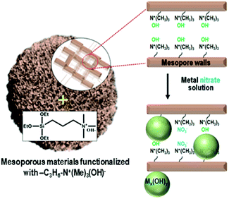
Herein, we present a strategy to solve the poor dispersion problem of non-noble metal catalysts at high loadings (∼25 wt%). The strategy is to induce a regioselective nucleation of inorganic precursors on the pore walls via surface functionalization with basic groups. One representative basic group is quaternary ammonium, Si(OC2H5)3–(CH2)3–N+(CH3)3(OH)−, which can be grafted onto the surface silanols through a simple silylation reaction. The ammonium group increases the basicity of the porous environment, causing nucleation or local precipitation of metal hydroxide even at a low concentration of the precursor species (Scheme 1). The precipitated metal hydroxide is converted to oxide (e.g., NiO, CuO or SnO2) nanoparticles in situ inside the pores upon air calcination at high temperatures. These nanoparticles can be used as highly dispersed oxide catalysts, or metal catalysts after appropriate reduction with H2. In the present work, we demonstrate that the strategy can be applied to various mesoporous supports that are crystalline or amorphous, such as mesoporous MFI zeolite nanosponge, MCM-48 mesoporous silica, and mesoporous γ-alumina.
A siliceous (aluminium-free) form of MFI zeolite nanosponge (SZN) was chosen as a representative support.13,14 The SZN sample was base-functionalized by the reaction with Si(OC2H5)3–(CH2)3–N+(CH3)3(OH)− (see Section S1 in the ESI† for Experimental details). The organic functionalization was confirmed by solid-state 1H-NMR spectroscopy (Fig. S1, ESI†). The maximal functionalization level was 1.0 mmol g−1, based on elemental analysis (EA). The ammonium-functionalized SZN, which is denoted as AF-SZN, exhibited no significant changes in the pore diameter and volume (Fig. S2, ESI†). In this step, although the zeolite was functionalized with ammonium hydroxide, the hydroxyl content was not high enough to complete the precipitation of nickel hydroxide when all the Ni(NO3)2 was added at once. Hence, prior to the addition, the Ni(NO3)2 solution was added with a suitable amount of NaOH solution, so that it could increase the pH to a point just below where precipitation began. The amount of NaOH solution was determined by a precipitation titration (Experimental details are given in Section S1 of the ESI†). After the pH adjustment, the solution was impregnated into AF-SZN by the incipient wetness method.
The AF-SZN sample after nitrate impregnation exhibited new peaks in the X-ray powder diffraction (XRD) analysis, in addition to peaks corresponding to the structure of the MFI zeolite nanosponge (Fig. S3, ESI†). These peaks could be assigned to reflections corresponding to nickel oxide hydroxide [PDF card No. 000130229]15 and nickel hydroxide [PDF card No. 010768988].16 We confirmed that the Ni species were located within the porous AF-SZN support even at 25 wt% Ni loading, using scanning transmission electron microscopy (STEM) images. On the other hand, when the pristine (i.e., unfunctionalized) SZN zeolite was impregnated with the same Ni precursor, no XRD peaks corresponding to nickel hydroxides appeared. Hence, we believe that the Ni precursor was impregnated as an amorphous phase. STEM images of the sample exhibited Ni species impregnated outside the porous zeolite matrix. As this result shows, ammonium functionalization was very effective in controlling the impregnation into the porous matrix. The loading of 25 wt% Ni is too high to explain by simple surface adsorption phenomena that can be induced by electrostatic or van der Waals interactions. As we proposed above, the base functional groups could cause a sharp increase in the local pH. As a result, the deposition–precipitation of nickel hydroxide could selectively occur inside the pores.17 In fact, a pH increase because of ammonium was confirmed by the purple colour of the functionalized zeolite when phenolphthalein solution was used as an indicator (Fig. S4, ESI†).
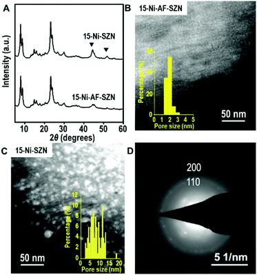
After the incipient wetness impregnation, the Ni precursor on the zeolite was converted to Ni oxide by calcination in air. Subsequently, the Ni oxide was reduced to Ni metal nanoparticles using H2. The resultant sample is denoted as x-Ni-AF-SZN or x-Ni-SZN, where x indicates the Ni wt%. The metal loading was determined by inductively coupled plasma atomic emission spectroscopy. Fig. 1 shows the XRD patterns and STEM images of 15-Ni-AF-SZN and 15-Ni-SZN. Both samples exhibited XRD peaks corresponding to the structure of the MFI zeolite nanosponge (Fig. 1) and two additional peaks centred at 45° and 52°. These peaks could be assigned to the (111) and (200) peaks of metallic Ni. The Ni metal peaks in the case of 15-Ni-AF-SZN were much lower in intensity than those of 15-Ni-SZN. This result indicated a much better Ni dispersion into the tiny metal nanoparticles in the case of the ammonium-functionalized zeolite support. The high dispersion was further clarified by the scanning transmission electron microscopy (STEM) images (Fig. 1B and C). In the case of 15-Ni-AF-SZN, the STEM image showed highly dispersed Ni nanoparticles with a narrow size distribution centred at 2 nm (Fig. 1B). The selected area diffraction pattern (SAED) image indicated that the Ni nanoparticles were crystalline (Fig. 1D). The particle diameters were much larger than the zeolite micropore diameters (0.6 nm). Considering that the mesopore diameters were approximately 4.5 nm, it was reasonable that the Ni nanoparticles were located inside the zeolite mesopores. This was also consistent with a significant decrease of the mesopore volume from 0.44 cm3 g−1 to 0.33 cm3 g−1 (Table S1, ESI†).
In contrast, the Ni nanoparticles supported on the SZN samples exhibited a poor dispersity with a broad particle size distribution ranging from 3 to 15 nm (Fig. 1C). Among the Ni nanoparticles, the particles larger than the mesopore diameter (∼4.5 nm) in size are expected to be mostly located on the particle surface of the SZN supports.
The Ni loading on AF-SZN could be increased to 25 wt% without a critical increase in the particle size or metal dispersion. STEM images of the 25 wt% sample (i.e., 25-Ni-AF-SZN) still exhibited a narrow distribution of Ni particle diameters although the mode value increased to 3.5 nm. At 30 wt%, however, much larger Ni particles than 5 nm were detected (Fig. S5, ESI†). The XRD peaks corresponding to the metallic Ni phase also became quite a distinct feature (Fig. S6, ESI†). This result indicates that a progressively increasing amount of Ni precursor was deposited outside the zeolite mesopores as the loading was increased beyond 25 wt%. This phenomenon can be attributed to blocking if an exceedingly large amount of Ni precursor is added to the zeolite even when the pore walls are functionalized with ammonium. The particle size trend depending on the Ni content and functionalization was further confirmed by CO and hydrogen chemisorption (detailed discussion in Section S3 of the ESI†).
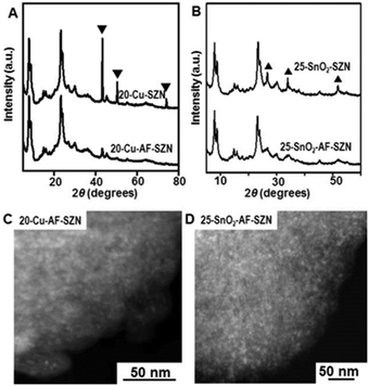
To demonstrate the versatility of our approach, we tested the same procedure for other kinds of metals or metal oxides. To this end, we supported 20 wt% Cu and 25 wt% SnO2 nanoparticles on AF-SZN samples (denoted by 20-Cu-AF-SZN and 25-SnO2-AF-SZN, respectively). Cu(NO3)2·3H2O and SnCl4·5H2O were used as the metal precursors (experimental details are given in Section S1 of the ESI†). Fig. 2A and B show the XRD patterns of Cu and SnO2 supported on AF-SZN samples (20-Cu-AF-SZN and 25-SnO2-AF-SZN). Average particle sizes calculated from XRD patterns using the Scherrer equation18 were 4.5 nm for Cu and 2.5 nm for SnO2. STEM images clearly showed that copper and tin oxide were highly dispersed on AF-SZN supports with narrow particle size distributions (Fig. 2C and D). In contrast, the dispersion of Cu and SnO2 nanoparticles over the pristine SZN support with identical amounts of loading exhibited only poor dispersion (Fig. 2A and B, top), as confirmed by XRD.
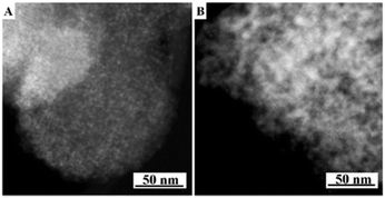
The present protocol can be used on other supports like amorphous mesoporous silica (e.g., MCM-48) and mesoporous γ-alumina (PURALOX® SBa 200, Sasol). The supports were treated with Si(OC2H5)3–(CH2)3–N+(CH3)3(OH)− in anhydrous ethanol for basic ammonium functionalization. The functionalized-ammonium group content was determined to be 1.0 mmol g−1 for MCM-48, and 0.3 mmol g−1 for γ-Al2O3. The organosilane could be covalently linked to the mesopore walls through the formation of Si–O–M (M = Si, Al) bonds.19 The resultant materials are denoted as AF-MCM-48 and AF-γ-Al2O3, respectively. The procedure for loading Cu nanoparticles was the same as that for 20-Cu-AF-SZN. Fig. 3A and B show the representative STEM images of 20-Cu-AF-MCM-48 and 20-Cu-AF-γ-Al2O3. The results clearly showed that Cu nanoparticles were homogeneously supported on AF-MCM-48 and AF-γ-Al2O3. It is noteworthy that the particle size distribution of the supported Cu nanoparticles was influenced very little by the type of supporting material (Fig. S7, ESI†). In particular, the textural properties (e.g., mesopore size distribution, specific surface area, and pore volume) of SZN, MCM-48, and γ-Al2O3 samples were very different (Fig. S8, ESI†). Thus, the high dispersion of metal nanoparticles with similar size distributions cannot be directly linked to the mesopore diameter of the supports. In contrast to the ammonium-functionalized supports, pristine MCM-48 and mesoporous γ-alumina exhibited poor dispersion of Cu nanoparticles at 20 wt% metal loading (Fig. S9, ESI†).
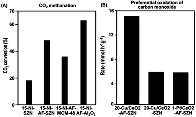
In order to investigate the effect of different supports on the catalytic properties of Ni, a series of 15 wt% Ni-based catalysts supported on AF-SZN, AF-MCM-48, and AF-γ-Al2O3 were prepared. All the samples exhibited a similar distribution of particle diameters in the STEM images (Fig. S10, ESI†). The CO chemisorption indicated a similar portion of surface Ni particles in all the three samples (see Sections S3 of the ESI†). We chose the hydrogenation of CO2 to methane as a probe reaction since Ni base materials are typical catalysts for this reaction. We used the CO2 conversion in 1 h under the reactant gas flow at 300 °C. The CO2 conversion in Fig. 4A shows a remarkable difference depending on the surface functionalization and supporting frameworks: 15-Ni-AF-γ-Al2O3 (63%), 15-Ni-AF-SZN (46%), 15-Ni-AF-MCM-48 (37%) and 15-Ni-SZN (18%). As this result shows, the alumina-supported nickel catalyst showed the highest catalytic conversion, which can be attributed to strong metal–support interactions. On the other hand, the mesoporous silica support, which does not have strong metal–support interactions, yielded a low catalytic conversion.20 Compared to mesoporous silica, the ammonium-functionalized zeolite catalyst (15-Ni-AF-SZN) is still in a high-purity silica form. Nonetheless, the zeolite catalyst exhibited quite a high CO2 conversion. Even after 45 h, the CO2 conversion of the 15-Ni-AF-SZN catalyst decreased only to 42%, indicating the high stability of the supported metal particles (Fig. S11, ESI†).
The merit of the ammonium functionalization was also remarkable when Cu and CeO2 were sequentially impregnated on porous supports. We supported 20 wt% Cu and 10 wt% CeO2 together on AF-SZN, and measured its catalytic activity for preferential oxidation of CO (experimental details are given in Section S1 of the ESI†). We used the CO conversion rate in 1 h under the reactant gas flow at 130 °C. The Cu/CeO2-AF-SZN catalyst achieved a conversion rate of approximately 15.2 CO mmol g−1 h−1. Compared to the results obtained from a previous report (5 wt% Cu/10 wt% CeO2–Al2O3), this value is five times higher at the same reaction temperature.21 Even their catalytic activity is three times higher than that of 1 wt% Pt/10 wt% CeO2-AF-SZN (Fig. 4B). Such a high catalytic activity can be attributed to a large number of surface active sites of high dispersion of supported Cu.
In conclusion, we demonstrated a high dispersion of supported metals (and metal oxides) by basic group-functionalization on various porous materials. The supported non-noble metal catalysts obtained here demonstrated the potential to replace noble-metal-based catalysts in the CO oxidation reaction. In addition, the present strategy yielded metal and metal oxide nanoparticles of mono-modal distributions, irrespective of the support materials, and supported species. We could thus reduce the complexity of interpretation of the catalytic results.22 Such a benefit is desirable for the design of supported catalysts. In addition, Gartmann et al. showed that functional groups could be selectively grafted at around the mesopore entrance of MCM-41.23 By using this strategy, we believe that the spatial distribution of supported metal particles is controlled by the location of functional groups in porous materials. Furthermore, the present method allows for the rational synthesis of multicomponent catalysts with a high interfacial area because two or more inorganic salts could be co-precipitated once they were in close proximity to the basic groups.
This work was supported by IBS-R004-D1. Dr Jo and Mr Cho thank Pavla Eliášová and Venkatesan Chithravel for valuable discussion.
Notes and references
- P. Munnik, P. E. de Jongh and K. P. de Jong, Chem. Rev., 2015, 115, 6687–6718 CrossRef CAS PubMed.
- R. J. White, R. Luque, V. L. Budarin, J. H. Clark and D. J. Macquarrie, Chem. Soc. Rev., 2009, 38, 481–494 RSC.
- Z. Li, T. He, L. Liu, W. Chen, M. Zhang, G. Wu and P. Chen, Chem. Sci., 2017, 8, 781–788 RSC.
- C. Wen, Y. Cui, W.-L. Dai, S. Xie and K. Fan, Chem. Commun., 2013, 49, 5195–5197 RSC.
- A. B. Laursen, I. C. Man, O. L. Trinhammer, J. Rossmeisl and S. Dahl, J. Chem. Educ., 2011, 88(12), 1711–1715 CrossRef CAS.
- X. Cui, X. Dai, Y. Deng and F. Shi, Chem. – Eur. J., 2013, 19, 3665–3675 CrossRef CAS PubMed.
- V. V. Kumar, G. Naresh, M. Sudhakar, C. Anjaneyulu, S. K. Bhargava, J. Tardio, V. K. Reddy, A. H. Padmasri and A. Venugopal, RSC Adv., 2016, 6, 9872–9879 RSC.
- M. K. van der Lee, A. J. van Dillen, J. H. Bitter and K. P. de Jong, J. Am. Chem. Soc., 2005, 127, 13573–13582 CrossRef CAS PubMed.
- J. H. Bitter, M. K. van der Lee, A. G. T. Slotboom, A. J. van Dillen and K. P. de Jong, Catal. Lett., 2003, 89, 139–142 CrossRef CAS.
- K. P. de Jong and J. W. Geus, Appl. Catal., 1982, 4, 41–51 CrossRef CAS.
- C. M. Lok, Stud. Surf. Sci. Catal., 2004, 147, 283–288 CrossRef CAS.
- G. L. Bezemer, P. B. Radstake, V. Koot, A. J. van Dillen, J. W. Geus and K. P. de Jong, J. Catal., 2006, 237, 291–302 CrossRef CAS.
- C. Jo, K. Cho, J. Kim and R. Ryoo, Chem. Commun., 2014, 50, 4175–4177 RSC.
- J. Kim, J. Chun and R. Ryoo, Chem. Commun., 2015, 51, 13102–13105 RSC.
- W. Feitknecht, H. R. Christen and H. Studer, Z. Anorg. Allg. Chem., 1956, 283, 88–95 CrossRef CAS.
- T. N. Ramesh and P. V. Kamath, Mater. Res. Bull., 2008, 43, 3227–3233 CrossRef CAS.
- P. Burattin, M. Che and C. Louis, J. Phys. Chem. B, 1998, 102, 2722–2732 CrossRef CAS.
- A. L. Patterson, Phys. Rev., 1939, 56, 978–982 CrossRef CAS.
- J. Zhao, M. Milanova, M. M. C. G. Warmoeskerken and V. Dutschk, Colloids Surf., A, 2012, 413, 273–279 CrossRef CAS.
- A. Marinoiu, C. Cobzaru, M. Raceanu, M. Varlam, E. Carcadea, C. Cernatescu and I. Stefanescu, Rev. Roum. Chim., 2015, 60, 249–256 Search PubMed.
- E. Moretti, M. Lenarda, L. Storaro, A. Talon, R. Frattini, S. Polizzi, E. Rodríguez-Castellón and A. Jiménez-López, Appl. Catal., B, 2007, 72, 149–156 CrossRef CAS.
- E. S. Vasiliadou, E. Heracleous, I. A. Vasalos and A. A. Lemonidou, Appl. Catal., B, 2009, 92, 90–99 CrossRef CAS.
- N. Gartmann and D. Brühwiler, Angew. Chem., Int. Ed., 2009, 48, 6354–6356 CrossRef CAS PubMed.
Footnote |
| † Electronic supplementary information (ESI) available: Experimental procedures, XRD, sorption, NMR, STEM, chemisorption, and catalytic stability results. See DOI: 10.1039/c7cc00479f |
| This journal is © The Royal Society of Chemistry 2017 |

![[thin space (1/6-em)]](https://www.rsc.org/images/entities/char_2009.gif) 000 mL h−1 g−1, H2
000 mL h−1 g−1, H2