Slow charge recombination in dye-sensitised solar cells (DSSC) using Al2O3 coated nanoporous TiO2 films
Emilio
Palomares
,
John N.
Clifford
,
Saif A.
Haque
,
Thierry
Lutz
and
James R.
Durrant
*
Centre for Electronic Materials and Devices, Department of Chemistry, Imperial College of Science, Technology and Medicine, Exhibition Road, London, UK SW7 2AY. E-mail: j.durrant@ic.ac.uk
First published on 7th June 2002
Abstract
The conformal growth of an overlayer of Al2O3 on a nanocrystalline TiO2 film is shown to result in a 4-fold retardation of interfacial charge recombination, and a 30% improvement in photovoltaic device efficiency.
In the last decade, dye-sensitised solar cells (DSSC) have been developed into one of the most interesting alternatives to current solar cell technology for the conversion of sunlight into electrical energy.1
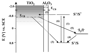
A typical DSSC comprises a dye sensitised porous, nanocrystalline titanium dioxide film interpenetrated by a liquid electrolyte containing an I−/I3− red/ox couple. The main charge-transfer events taking place at the TiO2/dye/electrolyte interface are depicted in Scheme 1. Visible light is absorbed (1) by the sensitiser dye (e.g.: RuL2(SCN)2 where L is 4,4′-dicarboxy-2,2′-bipyridyl). Electron injection (2) from the excited state of the dye into the conduction band of the TiO2 is followed by the subsequent regeneration of the dye by the I−/I3− red/ox couple (4).
 | ||
| Scheme 1 Illustration of the interfacial charge-transfer processes occurring at the nanostructured TiO2/dye/electrolyte interface of DSSC. Also shown is the Al2O3 blocking layer as developed in this paper. | ||
Efficient operation of the DSSC device relies upon the minimisation of the possible recombination pathways occurring at the TiO2/dye/electrolyte interface, allowing efficient charge transport through the TiO2 film and electrolyte and subsequent charge collection at the device contacts. There are two possible recombination losses to consider. The injected electrons may recombine either with oxidized dye molecules (3) or with the oxidised redox couple (5); the latter reaction is thought to be particularly critical to device function.
Increasingly research into DSSC is addressing the use of more sophisticated device architectures in order to reduce interfacial recombination losses. Examples include the use of composite metal oxides as the semiconductor e.g. SnO, ZnO with different band-gaps,2 the incorporation of spacer units between the oxidised dye and the TiO2 surface,4 and surface passivation by electrodeposition of insulating polymers.5 One particularly attractive approach involves the coating of the nanocrystalline metal oxide film with a thin overcoat of another metal oxide with a higher conduction band edge, as illustrated in Scheme 1, with the aim of increasing the physical separation of injected electrons for the oxidised dye redox couple, thereby retarding the recombination reactions. Previous studies employing this approach have demonstrated significant improvements in DSSC device performance for Nb2O5 coated TiO2 films and Al2O3 coated SnO2 films. 6,7
In this paper we employ transient laser spectroscopy to probe directly the retardation of interfacial charge recombination caused by coating a nanocrystalline TiO2 with an Al2O3 overlayer. We moreover suggest the simplicity of the coating method presented, may make this approach particularly attractive for the future development of efficient DSSC.
Al2O3 coated nanocrystalline TiO2 films were prepared by the following method. An 8 μm thick porous film of nanocrystalline, anatase TiO2 was deposited by the doctor blade technique onto fluorine doped conducting tin oxide glass (TEC8) (nanocrystal diameter ∼15 nm) as previously.8 An air-stable solution of Al(BuiO)3 (Sigma-Aldrich©, 99.9% grade, 0.15 M in isopropanol) under aerobic conditions was used to conformally coat the TiO2. The film was exposed to water vapour for 1 min and dried at 120 °C. After this, the film was dipped in the coating solution for 15 min at 60 °C and, finally, sintered at 450 °C for 15 min in order to remove any remaining organic contaminants. HRTEM data (data to be presented elsewhere) indicate this procedure resulted in a conformal Al2O3 overlayer with thickness of ∼2–2.5 nm. After coating, the samples were sensitised under anhydrous conditions by a standard solution of dye RuL2(NCS)2† overnight at room temperature, resulting in similar dye loadings for both films (see Table 1).
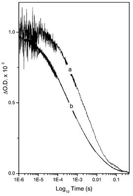
The influence of this coating procedure upon the kinetics of the recombination reaction (3) was determined using millisecond–microsecond transient absorption spectroscopy, monitoring the decay of photoinduced absorption of the dye cation species in the absence of a red/ox active electrolyte. Data were collected with the sensitised film covered in a 1∶1 ethylene carbonate/propylene carbonate solution and glass cover slide following previously published methods.9Fig. 1 contrasts the decay kinetics plotted on a logarithmic time scale in the presence and absence of the Al2O3 overcoat on the TiO2 film. The charge recombination kinetics exhibits the previously reported10 stretched-exponential behaviour (ΔOD ∝ e−(t/τ)a). It is apparent that the Al2O3 overlayer results in a ∼4 fold retardation of the recombination (half times for dye cation decay of 2.0 and 0.57 ms for the coated and uncoated films, respectively), consistent with the blocking layer function of the Al2O3 overlayer.
 | ||
| Fig. 1 Transient absorption data probing the decay of photoinduced dye cation absorption (excitation 625 nm, probe 800 nm) at room temperature for (a) an Al2O3/TiO2/RuL2(NCS)2 film and (b) a TiO2/ RuL2(NCS)2 film. The decay dynamics are assigned to the recombination reaction (3) in Scheme 1. | ||
The recombination data shown in Fig. 1 are consistent with a reasonably homogeneous Al2O3 overlayer thickness. An inhomogeneous overcoat would be expected to result in more dispersive (i.e. more stretched) recombination kinetics, whereas we observe the coating actually results in less dispersive kinetics (as will be discussed in more detail elsewhere). We furthermore note that coated films exhibited a similar initial signal amplitude to the uncoated films, indicative of similar electron injection yields for both films. This observation is consistent with previous studies11 of uncoated films which have reported that the rate of the electron injection reaction (2) is >103 greater than the excited state decay reaction (6), indicating the injection yield would be insensitive to a four-fold reduction in the rate of electron injection.
The influence of the Al2O3 overlayer on photovoltaic performance was investigated by the fabrication of a 1 cm2 ‘sandwich’ DSSC.‡ Photoelectrochemical measurements were performed according to reported procedures.
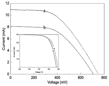
Fig. 2 illustrates the photocurrent–voltage curves for cells with and without blocking-layer of Al2O3. Open circuit voltage (VOC), short circuit photocurrent density (JSC), fill factor (FF), and photoenergy conversion efficiency (η) of the cells are listed in Table 1. We conclude that the Al2O3 overlay results in a significant improvement in Voc, Isc and FF, with an overall 30% improvement in device performance. The improvement in cell voltage is of particular relevance. It should be noted that the control (no overlayer) cells employed in these studies were optimised for compatibility with transient spectroscopy rather than device efficiency. As shown elsewhere, further improvements in device performance should be obtained by the use of scattering metal oxide films, reflective counter electrodes, and reduction in series resistance losses from the electrodes and electrolyte.
 | ||
| Fig. 2 Photocurrent–voltage curves of DSSC with (a) and without (b) the incorporation of an Al2O3 overlayer under AM 1.5 irradiation. The inset illustrates the dark current in both samples. | ||
The dark current data in Fig. 2 (see insert) indicates that the Al2O3 overlayer reduces the dark current arising from the recombination reaction (5) in Scheme 1. This is consistent with the observed 45 mV increase in Voc of the device under illumination and provides further support for the blocking layer function of the Al2O3 overlayer. In addition we find this overlayer results in a significant increase in Isc, as has been previously reported for Nb2O5 overlayers.6 This obervation may in part be attributed to an increase in the yield of electron injection, as we discuss above. It may also arise from other factors such as an improvement in electron transport through the metal oxide, as has previously been discussed in relation to TiCl4 treatments of such films.12
In conclusion we have demonstrated a simple method for the fabrication of conformal Al2O3 overlayer on nanocrystalline TiO2 films, have demonstrated that this overlayer results in a retardation of the kinetics of charge recombination to dye cations (reaction (3)) and a reduction in the dark current (reaction (5)), resulting in 30% overall improvement in device performance under solar illumination.
We gratefully acknowledge the support of the EPSRC and the European Union (Nanomax, NNE5-2001-00192) in funding this research.
Notes and references
- B. O’Regan and M. Grätzel, Nature, 1999, 353, 737 CrossRef.
- K. Tennakone, V. P. S. Perera, I. R. M. Kottegoda and G. R. A. Kum, J. Phys. D: Appl. Phys., 1999, 32, 374 Search PubMed.
- M. K. Nazeeruddin, A. Kay, I. Rodicio, R. Baker Humphry, E. Muller, P. Liska, N. Vlachopoluos and M. Gratzel, J. Am. Chem. Soc., 1993, 115, 6382 CrossRef CAS.
- R. Argazzi, C. A. Bignozzi, T. A. Heimer and G. J. Meyer, Inorg. Chem., 1997, 36, 2 CrossRef CAS.
- B. A. Gregg, F. Pichot, S. Ferrere and C. L. Fields, J. Phys. Chem. B., 2001, 105, 1422 CrossRef CAS.
- A. Zaban, S. G. Chen, S. Chappel and B. A. Gregg, Chem. Commun., 2000, 2231 RSC.
- G. R. R. A. Kummara, K. Tennakone, V. P. S. Perera, V. A. Kono, S. Kaneko and M. Okuya, J. Phys. D: Appl. Phys., 2001, 34, 868 Search PubMed.
- R. L. Willis, C. Olson, B. O’Regan, T. Lutz, J. Nelson and J. R. Durrant, J. Phys. Chem. B, 2002, in press CrossRef CAS.
- S. A. Haque, Y. Tachibana, R. L. Willis, J. E. Moser, M. Grätzel, D. R. Klug and J. R. Durrant, J. Phys. Chem. B, 2000, 104, 538 CrossRef CAS.
- S. A. Haque, Y. Tachibana, D. R. Klug and J. R. Durrant, J. Phys. Chem. B, 1998, 102, 1745 CrossRef CAS.
- Y. Tachibana, J. E. Moser, M. Grätzel, D. R. Klug and J. R. Durrant, J. Phys. Chem., 1996, 100, 20056 CrossRef CAS.
- N.-G. Park, J. Schlichthorl, H. M. van de Lagemaat, A. Cheong, A. J. Mascarenhas and J. Frank, J. Phys. Chem. B, 1999, 103, 3308 CrossRef CAS.
Footnotes |
| † Chemical name: cis-bis(isothiocyanato)bis(2,2′-bipyridyl-4,4′-dicarboxylato)ruthenium(II) bis-tetrabutylammonium. |
| ‡ The electrolyte solution contains 2.216 g of tetrabutylammonium iodide (0.6 M), 0.134 g LiI (0.1 M), 0.253 g I2 (0.1 M) and 0.676 g 4-tert-butylpyridine (0.5 M) in 10 ml of acetonitrile. The counter electrode was made using a solution of chloroplatinic acid (1 g of acid in 40 ml of isopropanol). |
| This journal is © The Royal Society of Chemistry 2002 |
