A six-fold difference in structure results in a six-order difference in conductivity: silica shell nanoarchitectonics on carbon black particles†
Takaaki
Yoshida
a and
Makoto
Ogawa
 *b
*b
aGraduate School of Creative Science and Engineering, Waseda University, Nishiwaseda 1-6-1, Shinjuku-ku, Tokyo 169-8050, Japan
bSchool of Energy Science and Engineering, Vidyasirimedhi Institute of Science and Technology (VISTEC), 555 Moo 1 Payupnai, Wangchan, Rayong 21210, Thailand. E-mail: makoto.ogawa@vistec.ac.th
First published on 20th April 2022
Abstract
Carbon black (Ketchen Black with a particle size of several tens of nm) was coated with silica with a varied thickness of 2 and 12 nm. Carbon/silica core–shell particles were grafted with the γ-methacryloxypropylsilyl group to be homogeneously dispersed into a poly(methyl methacrylate) film. The electrical conductivity of the poly(methyl methacrylate) films containing carbon/silica particles was successfully controlled by the thickness of the silica layer; silica coating with 2 nm thickness gave a conducting film, while that with 12 nm thickness gave a less conducting film with a remarkable difference on the order of 106 (in volume conductivity).
The modification of surface properties by the deposition of a thin layer coating has been a topic of interest from both scientific and practical viewpoints. The coating of particle surfaces with an ultrathin layer led to useful effects such as suppressed particles’ aggregation, the stabilization of the suspension for paint and ink application, and molecular recognition for catalysts and adsorbents, and so on.1–3 For these purposes, coating with a molecular layer (self-assembly) of organic species such as surfactants, silane coupling reagents and polymers has been reported extensively.2,3 Inorganic thin layers have also been prepared on particles’ surface to modify the surface properties.3–7 Among possible coating, the deposition of a thin silica layer on the particle's surface has been reported extensively.8 When homogeneous coating was achieved, the core can be removed by combustion or dissolution to obtain hollow silica particles.8–11 The thickness and homogeneity (or selective deposition) of the coating are factors toward the precise design of the properties of the resulting materials. The variation of the composition and structure of the silica layer designed by hybridization makes the coating more versatile for the preparation of functional composite core–shell particles and the application of the resulting core–shell particles includes bio and medical ones to energy and environmental issues.12–16
In this study, the deposition of a silica layer on carbon black (Ketchen Black) was investigated. Carbon materials of various forms are useful pigments and fillers and have been used in a wide range of applications.17–19 The deposition of metal oxides on carbons has been done in order to modify the surface properties for the materials’ application.20–25 The coating of metal oxides on carbon materials has also been done by means of CVD, PVD, slurry coating and sol–gel reactions.20–31 Metal oxide-coated carbons have also been used as precursors of non-oxide ceramics such as carbides, where the carbon core was used as a reducing reagent in the carbothermal reduction24,25 and the resulting carbide layer is expected to act as a protecting layer from combustion. In addition to the application of the coated carbon for polymer additives, batteries, catalysts, and sensors,20 core–shell particles have been used to obtain oxide tubes or hollow spheres after the removal of the carbon core.28–31
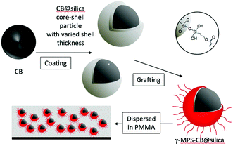
Carbon black has been used as a filler to obtain black polymers with high electrical and thermal conductivity coming from the connection of conducting carbon black particles in the polymers. In order to obtain the homogeneous dispersion of CB in polymers, a stable dispersion of CB has been prepared with the help of a surfactant as a dispersant. Several kinds of dispersants have been developed so far.32–36 In the present study, the preparation of black polymer coating (poly(methylmethacrylate); abbreviated as PMMA) with controlled resistivity was examined by the hybridization of carbon black with the polymer. Surface modification of CB was done to obtain a stable dispersion of carbon black in an organic solvent. A homogeneous dispersion of carbon black particles in PMMA was achieved, without using dispersants, by the coating of carbon black with silica and the subsequent modification of the surface of particles with the γ-methacryloxy group as schematically shown in Fig. 1.
 | ||
| Fig. 1 Schematic representation of the coating, the grafting with γ-MPS, and the dispersion of the modified CB into PMMA. | ||
The carbon black–silica composite particle (hereafter termed CB@silica) was prepared by the deposition of a silica layer on the surface of carbon black from a solution based on the method described in our previous papers on the deposition of a nanoporous silica layer on solids.37–39 Hexadecyltrimethylammonium (abbreviated as CTA) chloride, deionized water (17.7 g), 28% aqueous ammonia solution (7.2 g) and carbon black (CB, 75 mg) were mixed under ultrasonication for 10 minutes. Then, methanol (200 mL) was added and the mixture was ultrasonicated for another 5 minutes. Commercially available carbon black (Ketchen Black) was used. Tetraethoxysilane (abbreviated as TEOS, 0.368 mL) was added to the suspension and the suspension was aged at room temperature for 1 h. The solid particles were collected by suction filtration and dried in air at room temperature for 2 days.
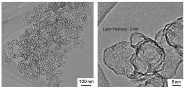
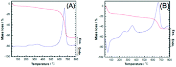
The coating of carbon black with silica was confirmed by TG-DTA as well as TEM images. The TG-DTA curves of the silica-coated CB are shown in Fig. 2. In addition to the weight loss, which accompanied the exothermic reaction in the corresponding DTA curve at around 600–700 °C, due to the oxidative decomposition of CB, exothermic reactions accompanying a weight loss due to the decomposition of the occluded CTA in the coating were observed at around 300 °C. The decomposition was consistent with the coating of the silica-surfactant mesostructured materials on the particle surfaces.37–39 In order to obtain a clearer image of the successful coating, CB@silica was calcined in air at 700 °C to remove CB for the TEM observation. The TEM images of the calcined CB@silica are shown in Fig. 3, where hollow particles with a thickness of a few nm are seen. The shape of the hollow particles is consistent with the shape of CB (the TEM images of pristine CB are shown in Fig. S1†).
 | ||
| Fig. 3 TEM images of CB@silica after calcination at 700 °C. (Left) Low and (right) and high magnification. | ||
A preliminary experiment to disperse CB@silica into a poly(methyl methacrylate) (abbreviated as PMMA) film by mixing the particles in a dimethylformamide solution of PMMA was not successful, due to the poor affinity of CB@silica with PMMA. The photograph of the resulting film is shown in Fig. 4A. In order to modify the surface properties of the silica layer on carbon black to be compatible with the organic polymer (PMMA), the attachment of the γ-methacryloxysilyl group (hereafter abbreviated as γ-MPS) was done taking advantage of the possible grafting of an organic functionality through silylation of the silanol group of silica. The grafting of the γ-MPS group on a layered silicate was done to modify the surface properties of the layered silicate to be hybridized with PMMA.40 CB@silica was allowed to react with γ-methacryloxypropyltrimethoxysilane to immobilize γ-MPS groups on the surface through the hydrolysis and the condensation of γ-methacryloxypropyltrimethoxysilane by the following procedure; CB@silica (150 mg) was mixed with 90 ml of toluene containing 0.51 mL of γ-methacryloxypropyltrimethoxysilane. The mixture was refluxed at 60 °C for 3 days under nitrogen and after the reaction, the solvent was removed using a rotary evaporator at 60 °C under reduced pressure (90 hPa). In the TG-DTA curves (Fig. S2†) of the product, an exothermic reaction and the weight loss in the DTA and TG curves due to the oxidative decomposition of γ-MPS groups were seen, suggesting the successful attachment of γ-MPS groups on CB@silica.
 | ||
| Fig. 4 Photographs of (A) PMMA-CB silica film, (B) suspension of γ-MPS-CB@silica and pristine CB in chloroform, (C) PMMA-CB@silica film, and (D) PMMA-CB@sliica-12 nm film. | ||
The modified CB (designated as γ-MPS-CB@silica, 72 mg) was mixed with chloroform (1.5 mL) under sonication for 10 min and poly(methyl methacrylate) (30 mg) was added and the suspension was mixed with magnetic stirring for 30 min to obtain a homogeneous suspension as shown in Fig. 4B. No sedimentation was seen after the storage of the suspension at room temperature. The suspension was spin-coated (at 2800 rpm) on an aluminum plate and dried at 60 °C for 1 min to obtain a homogeneous black film. The photograph of the film (γ-MPS-CB@silica in PMMA) is shown in Fig. 4C. The conductivity of the film (with a thickness of ca. 1.0 μm) was evaluated by applying the electric field (30 V) with aluminum electrodes. The experimental set-up for the measurement is given in Fig. S3.† The film was conductive with a volume resistivity of ca. 4 × 10⁻⁵ ohm cm as determined from the measured resistivity of 10 ohm (a conductance of 3 A was seen by applying 30 V). This relatively high conductivity was thought to be caused by the connection of the CB particles through the cracking of the silica coating and the tunneling effect41 through a thin silica layer (2 nm thick) between the adjacent CB particles.
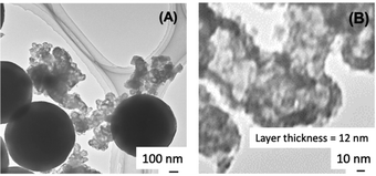
In order to vary the conductivity of the film, which was thought to be caused by the connection of the CB particles, the thickness and the homogeneity of the coating were examined with the expectation that the thicker silica shell will prevent the connection of the CB particles. The thickness of the silica layer on oxide particles has been controlled by changing the TEOS concentration or solvent in the starting solution in the presence of a surfactant and by the repeated coating procedure.14–18 In the present study, the sample preparation was optimized to obtain a thicker layer of silica on CB by employing a larger amount of TEOS for the coating procedure. Details are given as follows: CTA chloride, deionized water (17.7 g), 28% aqueous ammonia solution (7.2 g) and carbon black (CB, 75 mg) were mixed under ultrasonication for 10 minutes; subsequently, methanol (200 mL) was added and the mixture was sonicated for another 5 minutes. Then, TEOS (3.68 mL) was added to the suspension and the suspension was aged at room temperature for 1 day. The solid was collected by suction filtration and dried in air at room temperature for 2 days. The TEM image of the sample after calcination at 700 °C is shown in Fig. 5A, where the coating on carbon black became thick (13 nm) if compared with the sample prepared by the experiment using a low TEOS concentration (Fig. 3).
In addition to the coated CB, as a result of homogeneous nucleation in solution, spherical particles of silica42 formed as shown in the TEM image (Fig. 5A). In order to avoid contamination with the spherical silica particles, the reaction conditions were optimized by shortening the reaction time (from 1 day to 1 h) expecting that TEOS was consumed preferentially on CB for the coating and the excess TEOS subsequently reacted to form the spherical particles of silica. The suspension after the reaction for 1 hour was immediately filtered to separate the silica-coated CB before the homogeneous nucleation of spherical silica particles. The TEM images of the product (after calcination at 700 °C) are shown in Fig. 5B to show that CB was coated with a 12 nm thick silica layer. Hereafter, the sample is named CB@silica-12 nm. The thicker coating was supported by the TG-DTA curves of CB@silica-12 nm, which are shown in Fig. S4,† where weight losses due to the oxidative decomposition of the surfactant and CB were observed at 300 and 600 °C, respectively. The weight of the ash corresponded to the silica content (25 and 55 wt% for CB@silica and CB@silica-12 nm, respectively) in the core–shell particles.
The surface modification of CB@silica-12 nm with γ-methacryloxypropyltrimethoxysilane was done by the procedure mentioned above and the resulting organically modified CB@silica-12 nm was incorporated into the PMMA film by spin-coating the suspension in a chloroform solution of PMMA. In the TG-DTA curves of γ-MPS-CB@silica-12 nm (Fig. S3†), an exothermic reaction and the weight loss in the DTA and TG curves due to the oxidative decomposition of γ-MPS groups were observed, suggesting the successful attachment of γ-MPS groups on CB@silica-12 nm. A hmogeneous black film with a thickness of ca. 1.3 μm was obtained with a similar CB content when γ-MPS-CB@silica was used. The film of PMMA-γ-MPS-CB@silica-12 nm gave a resistivity of over ca. 7 × 10¹¹ ohm cm (no conduction was detected in the set-up given in Fig. S3†), which is low by the order of 106 if compared with the value (4 × 10⁵ ohm cm) obtained for γ-MPS-CB@silica, showing the important role of the shell thickness (2 and 12 nm) on the conductivity. Thus, the material design based on the coating with a precisely designed thickness as well as the organic modification of the surface are applicable to other carbon materials and with varied organic functionalities for versatile material application including optical, thermal and electrical conduction.
In conclusion, carbon black was successfully coated with a homogeneous thin layer of silica. The subsequent grafting with γ-methacryloxypropyltrimethoxysilane through the silylation of a silica shell was possible to achieve the homogeneous dispersion of a carbon black (Ketchen Black) pigment into a poly(methyl methacrylate) film without using an additional dispersant. The conductivity was substantially (six order) modified for the polymer films with a similar carbon black content by changing the thickness of the silica layer from 2 to 12 nm (only 6 times difference), showing the important role of the precise control of the coating in the materials’ performances.
Conflicts of interest
There are no conflicts to declare.Acknowledgements
This work was supported by the Distinguished Professor Grant (grant number N41A640072) from the National Research Council of Thailand (NRCT), Thailand and a Moonshot project (grant number JPNP18016) from the New Energy and Industrial Technology Development Organization (NEDO), Japan.Notes and references
- A. K. Sen, Coated Textiles Principles and Applications, CRC Press, Boca Raton, 2008 Search PubMed; T. Schneller, R. Waser, M. Kosec and D. Payne, Chemical Solution Deposition of Functional Oxide Thin Films, Springer, 2013 Search PubMed.
- A. Ulman, An Introduction to UItrathin Organic Films from Langmuir Blodgett to Self-Assembly, Academic Press Inc., San Diego, 1991 Search PubMed.
- (a) M. Ogawa, Annu. Rep. Prog. Chem., Sect. C: Phys. Chem., 1998, 94, 209 RSC; (b) R. Ghosh Chaudhuri and S. Paria, Chem. Rev., 2012, 112, 2373 CrossRef CAS PubMed.
- R. Ma and T. Sasaki, Acc. Chem. Res., 2015, 48, 136 CrossRef CAS PubMed.
- Y.-H. Yang, C.-H. Liu, Y.-H. Liang, F.-H. Lin and K. C. W. Wu, J. Mater. Chem. B, 2013, 1, 2447 RSC.
- B. P. Bastakoti, Y.-C. Hsu, S.-H. Liao, K. C. W. Wu, M. Inoue, S. Yusa, K. Nakashima and Y. Yamauchi, Chem. – Asian J., 2013, 8, 1301 CrossRef CAS PubMed.
- V. Malgras, Q. Ji, Y. Kamachi, T. Mori, F.-K. Shieh, K. C. W. Wu, K. Ariga and Y. Yamauchi, Bull. Chem. Soc. Jpn., 2015, 88, 1171 CrossRef CAS.
- (a) M. Ogawa, Chem. Rec., 2017, 17, 217 CrossRef CAS PubMed; (b) K. Shiba, T. Takei, G. Yoshikawa and M. Ogawa, Nanoscale, 2017, 9, 16791 RSC.
- Y. Bao, C. Shi, T. Wang, X. Li and J. Ma, Microporous Mesoporous Mater., 2016, 227, 121 CrossRef CAS.
- (a) B. Tan and S. E. Rankin, Langmuir, 2005, 21, 8180 CrossRef CAS PubMed; (b) P. A. Williamson, P. J. Blower and M. A. Green, Chem. Commun., 2011, 47, 1568 RSC.
- N. Shimura and M. Ogawa, J. Colloid Interface Sci., 2007, 312, 311 CrossRef CAS PubMed.
- Y. Zhang, B. Y. W. Hsu, C. Ren, X. Li and J. Wang, Chem. Soc. Rev., 2015, 44, 315 RSC.
- M. B. Gawande, A. Goswami, T. Asefa, H. Guo, A. V. Biradar, D.-L. Peng, R. Zboril and R. S. Varma, Chem. Soc. Rev., 2015, 44, 7540 RSC.
- A. M. El-Toni, M. Habila, J. P. Labis, Z. A. Alothman, M. Alhoshan, A. A. Elzatahry and F. Zhang, Nanoscale, 2016, 8, 2510 RSC.
- (a) R. Hayes, A. Ahmed, T. Edge and H. Zhang, J. Chromatogr. A, 2014, 1357, 36 CrossRef CAS PubMed; (b) S. Sanchez-Salcedo, M. Vallet-Regí, S. A. Shahin, C. A. Glackin and J. I. Zink, Chem. Eng. J., 2018, 340, 114 CrossRef CAS; (c) Y. Li, R. Wang, Y. Xu, W. Zheng and Y. Li, Inorg. Chem., 2018, 57, 8012 CrossRef CAS PubMed.
- (a) S. J. Cheepborisutikul and M. Ogawa, Inorg. Chem., 2021, 60, 6201 CrossRef CAS PubMed; (b) J. Gamonchuang, N. Khaorapapong and M. Ogawa, Colloids Surf., A, 2016, 511, 39 CrossRef CAS.
- K. Kinoshita, Carbon: Electrochemical and Physicochemical Properties, Wiley, 1988 Search PubMed.
- J. E. Morris and K. Iniewski, Graphene, Carbon Nanotubes, and Nanostructures: Techniques and Applications, CRC Press, Boca Raton, 2013 Search PubMed.
- Carbon Black: Science and Technology, ed. J.-B. Donnet, Marcel Dekker, New York, 2nd edn, 1993 Search PubMed.
- G. Arabale, D. Wagh, M. Kulkarni, I. Mulla, S. Vernekar, K. Vijayamohanan and A. Rao, Chem. Phys. Lett., 2003, 376, 207 CrossRef CAS.
- L. Noerochim, J. Z. Wang, S. L. Chou, H. J. Li and H. K. Liu, Electrochim. Acta, 2010, 56, 314 CrossRef CAS.
- A. Gomathi, S. R. C. Vivekchand, A. Govindaraj and C. N. R. Rao, Adv. Mater., 2005, 17, 2757 CrossRef CAS.
- Y. Deslandes and F. N. Sabir, J. Mater. Sci. Lett., 1990, 9, 200 CrossRef CAS.
- R. Gadiou, S. Serverin, P. Gibot and C. Vix-Guterl, J. Eur. Ceram. Soc., 2008, 28, 2265 CrossRef CAS.
- K. Itatani, J. Kita, I. J. Davies and H. Suemasu, Carbon Nanotubes: Res. Appl., 2010, 8, 125–140 Search PubMed.
- W. Wang, P. Serp, P. Kalck and L. J. Faria, Appl. Catal., B, 2005, 56, 305 CrossRef CAS.
- S. A. Ntim and S. Mitra, J. Colloid Interface Sci., 2012, 375, 154 CrossRef PubMed.
- B. C. Satishkumar, A. Govindaraj, E. M. Vogl, L. Basumallick and C. N. R. Rao, J. Mater. Res., 1997, 12, 604 CrossRef CAS.
- M. Zheng, J. Cao, X. Chang, J. Wang, J. Liu and X. Ma, Mater. Lett., 2006, 60, 2991 CrossRef CAS.
- M. Kim, J. Hong, J. Lee, C. K. Hong and S. E. Shim, J. Colloid Interface Sci., 2008, 322, 321 CrossRef CAS PubMed.
- H. Ogihara, S. Masahiro, Y. Nodasaka and W. Ueda, J. Solid State Chem., 2009, 182, 1587 CrossRef CAS.
- K. H. Kuo, W. Y. Chiu, K. H. Hsieh and T. M. Don, Eur. Polym. J., 2009, 45, 474 CrossRef CAS.
- F. Nsib, N. Ayed and Y. Chevalier, Prog. Org. Coat., 2006, 55, 303 CrossRef CAS.
- Z. Wang, Q. Liu, H. Zhu, H. Liu, Y. Chen and M. Yang, Carbon, 2007, 45, 285 CrossRef CAS.
- M. G. C. Kahn, S. Banerjee and S. S. Wong, Nano Lett., 2002, 2, 1215 CrossRef CAS.
- K. A. S. Fernando, Y. Lin and Y.-P. Sun, Langmuir, 2004, 20, 4777 CrossRef CAS PubMed.
- K. Shiba, T. Takei and M. Ogawa, Dalton Trans., 2016, 45, 18742 RSC.
- M. Ogawa, N. Shimura and A. Ayral, Chem. Mater., 2006, 18, 1715 CrossRef CAS.
- Y. Ide, Y. Koike and M. Ogawa, J. Colloid Interface Sci., 2011, 358, 245 CrossRef CAS PubMed.
- K. Isoda, K. Kuroda and M. Ogawa, Chem. Mater., 2000, 12, 1702 CrossRef CAS.
- M. Hiroshima, Jpn. J. Appl. Phys., 1994, 33, 395 CrossRef CAS.
- N. Shimura and M. Ogawa, J. Mater. Sci., 2007, 42, 5299 CrossRef CAS.
Footnote |
| † Electronic supplementary information (ESI) available. See DOI: https://doi.org/10.1039/d2nr01714h |
| This journal is © The Royal Society of Chemistry 2022 |


