DOI:
10.1039/D2NR00060A
(Paper)
Nanoscale, 2022,
14, 6557-6569
Ruthenium nanoparticles integrated bimetallic metal–organic framework electrocatalysts for multifunctional electrode materials and practical water electrolysis in seawater†
Received
5th January 2022
, Accepted 23rd March 2022
First published on 26th March 2022
Abstract
There is still a significant technical hurdle in the integration of better electrocatalysts with coordinated functional units and morphological integrity that improves reversible electrochemical activity, electrical conductivity, and mass transport capabilities. In this work, ruthenium-integrating porous bimetallic transition metal nanoarrays are efficiently generated from metal–organic framework-covered three-dimensional platforms such as carbon cloth using a simple solution-based deposition technique followed by calcination. Heterostructure ruthenium–cobalt–iron hollow nanoarrays are built to permit exceptionally effective multifunctional activities in reactions including the oxygen evolution reaction, hydrogen evolution reaction, and oxygen reduction reaction. As presumed, the as-synthesized porous nanostructured arrays show remarkable electrochemical performance due to the benefits of copious active reaction sites, and efficient electron and ion transport channels. The oxygen reduction reaction of the porous nanostructured array electrocatalyst has a half-wave potential of 0.875 V vs. reversible hydrogen electrode and can achieve a current density of 10 mA cm−2 at low overpotentials of 220 and 50 mV for the oxygen and hydrogen evolution reactions, respectively, and the needed cell voltage for total water splitting is just 1.49 V at a current density of 10 mA cm−2. The fabricated electrolyzer coupling splits seawater at relatively low cell voltages of 1.54 V at ambient temperature.
1. Introduction
As a long-lasting and sustainable clean fuel, hydrogen has been considered a viable candidate to replace declining fossil fuels.1 Because of its remarkable energy density, great energy conversion efficiency, and zero carbon emission, molecular hydrogen is an attractive largest source of energy for addressing future energy concerns.2 Water electrolysis is a well-known process for producing ultrapure hydrogen, and it offers a viable solution to sustainable hydrogen production by utilizing renewable electricity sources.3 Because of the adverse thermodynamics and slow reaction kinetics of both the hydrogen evolution reaction (HER) and oxygen evolution reaction (OER) mechanisms, generating high-performance electrocatalysts that can decrease the activation energy barrier and increase the reaction rate is critical, but is still very much an obstacle.4 Highly developed catalysts, including Pt-based materials and IrO2 with low overpotential and efficient kinetics for the HER and OER, play an increasingly important role in the implementation of water splitting processes.5 Despite their efficiency, exorbitant cost and scarcity in the environment severely limit their wider commercial applicability. These shortcomings need the design of more active and long-lasting catalysts with decreased noble metal load levels.6 As a result, several approaches for generating equally distributed catalysts with diverse nanostructured topologies have been established, such as synthesizing atomically dispersed noble metal catalysts, alloying noble metals with transition metals, and enhancing metal–support connections.7–10
Considerable efforts have been made to investigate cost-effective OER, HER, and ORR electrocatalysts, and many transition-metal-based catalysts have been thoroughly investigated and synthesized.11,12 Notably, transition metal derivatives (TMDs) have sparked the interest of researchers due to several advantages in terms of ease of synthesis, low cost, and easily adjustable structure and composition.13 On the other hand, the intrinsically low electrical conductivity of the majority of the TMD catalysts significantly hampered efficient electron transport, decreasing electrocatalytic OER, HER, and ORR activity.14 Furthermore, active sites are typically situated beneath the surface, resulting in limited access to active sites and low mass activity.15 As a result, deliberately adjusting and enhancing TMD electronic characteristics is an intriguing strategy for improving electrochemical performance. In terms of electrical characteristics and electron transport, heteroatom doping or positive inclusion of active sites is advantageous for changing the electrical properties and improving the catalytic active sites.16 In short, noble metals hosted on foreign templates permit composite entities with altered chemisorptive and catalytic capabilities, thereby removing limitations and increasing the benefits of solitary analogues.17,19 Consequently, selecting an acceptable template and producing the related precious metal nanostructures would be vital. Specifically, ruthenium (Ru) has been demonstrated to have acceptable adsorption energies for adsorbed oxygen (Oads) due to its availability of d-orbital electrons, and it is of low cost, paving the way for the development of high-performance OER and HER electrocatalysts.20,21 It has been observed that alloying noble metals with other TMDs, with the loading of noble metal lowered by a large factor, is a major route to generating exceptionally effective catalysts with a good cost-competitive balance.22 Furthermore, the existing literature has shown that changes in the average energy of the d-band and the width of the d-band are caused by the total combined strain and ligand effects caused by the formation of heteroatom bonds and the modification of the bond length can alter the chemical and physical properties of bimetallic surfaces.23 Thus, the noble-transition bimetallic alloys could greatly enhance the electrocatalytic abilities caused by the change in charge distributions and subsequent adjustment of surface properties during alloy formation.19,24
Metal–organic frameworks (MOFs) derived from transition metal ions and organic ligands have often been used as substrates for the synthesis of a wide range of nanostructures due to their highly modifiable structure, pore size, and metal sites.25 Nonetheless, because of their low conductivity, limited water stability, and lack of accessibility to active metal centers, pure MOFs have been ineffective as electrocatalysts.26 In the case of bulk MOFs that were sensitive to organic linkers and thus exhibited restricted electrolyte accessibility, a significant proportion of active sites were exposed toward the pores or channels.27 To address these drawbacks, 2D structured MOFs with faster electron and mass transport and a larger specific surface have been produced and are receiving more and more attention.28,29 The 2D MOF analogues not only maintain the structural and morphological features of MOFs but also improve the electrical properties, boosting the electrocatalytic ability of multifunctional electrocatalysts.30
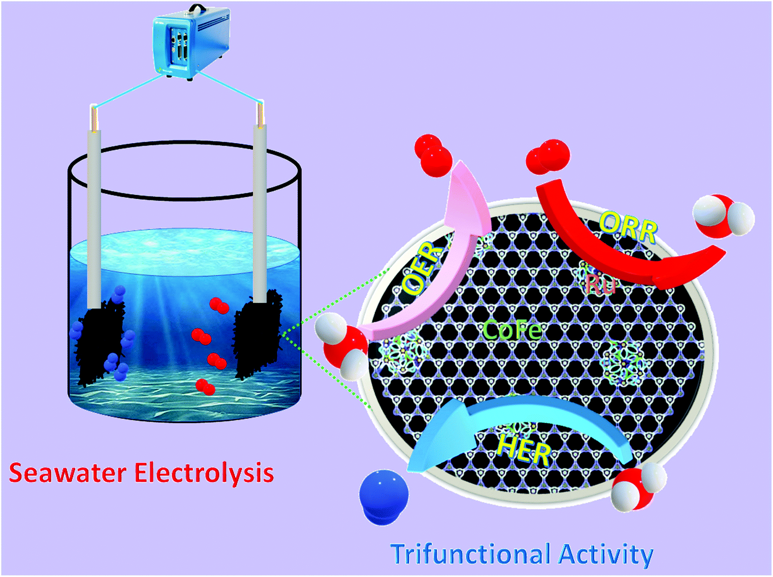
Given that a composite catalyst consisting of Ru doped bimetallic MOFs might have a huge electrochemical specific surface area when appropriately constructed. In this work, Ru doping into CoFe bimetallic nanoarrays generated from 2D MOF nanoarrays on carbon cloth was developed and synthesized using a continuous two-step solution deposition followed by the calcination method. The prepared nanostructure demonstrated enhanced electrocatalytic activity for the OER, HER, and ORR under alkaline conditions, owing to preferential switchable electronic structure-stimulated synergism, which imbues excellent electrical conductivity, adequate water adsorption energy, and faster charge transfer kinetics. Interestingly, the two-electrode water splitting device assembled with Ru doped bimetallic MOFs as electrode materials illustrated extremely high electrocatalytic performance with a cell voltage of 1.49 V at 10 mA cm−2 and extremely good long-term durability. The electrolyzer built on Ru MOF CoFe nanoarrays can perform seawater splitting at 1.54 V at 10 mA cm−2, a minimum cell voltage is necessary to meet industrial production. Our study emphasizes the conceptual design of MOF-derivates and provides an excellent strategy for boosting the intrinsic activity of active species, which may be used to construct even more remarkable multifunctional electrocatalysts (Scheme 1).
 |
| | Scheme 1 Schematic diagram of seawater electrolysis and electrochemical activities toward the OER, HER, and ORR. | |
2. Experimental section
2.1. Chemicals
Cobalt nitrate hexahydrate (Co(NO3)2·6H2O), potassium hexacyanoferrate(III) K3[Fe(CN)6], 99%), 2-methylimidazole (Hmim), and ruthenium chloride (RuCl3·3H2O were purchased from Sigma Aldrich. Ethanol was acquired from Showa Chemical Co. Ltd. All other chemicals were used as received without any further purification.
2.2. Synthesis of MOF Co nanoarrays
To synthesize MOF Co nanoarrays, first, a piece of bare carbon cloth (2 × 5 cm2 CC) was soaked in a mixed solution (1![[thin space (1/6-em)]](https://www.rsc.org/images/entities/char_2009.gif) :1, v/v) of concentrated sulfuric acid and 30% H2O2 with ultrasonic treatment at room temperature for 2 h, after that, the pretreated CC was rinsed with water and ethanol. Separately, aqueous solutions comprising 0.4 M 2-methylimidazole (Hmim) and 50 mM Co(NO3)2·6H2O were each prepared in 40 ml of deionized water with constant stirring at room temperature. Then, the two solutions were quickly mixed and stirred for 10 minutes and a piece of pretreated CC substrate (2 × 5 cm2) was submerged in the mixture solution for 1 h at room temperature. After 1 h of reaction at room temperature, the MOF Co nanoarray growth CC sample was removed, washed with deionized water, and dried overnight in an electrical oven.
:1, v/v) of concentrated sulfuric acid and 30% H2O2 with ultrasonic treatment at room temperature for 2 h, after that, the pretreated CC was rinsed with water and ethanol. Separately, aqueous solutions comprising 0.4 M 2-methylimidazole (Hmim) and 50 mM Co(NO3)2·6H2O were each prepared in 40 ml of deionized water with constant stirring at room temperature. Then, the two solutions were quickly mixed and stirred for 10 minutes and a piece of pretreated CC substrate (2 × 5 cm2) was submerged in the mixture solution for 1 h at room temperature. After 1 h of reaction at room temperature, the MOF Co nanoarray growth CC sample was removed, washed with deionized water, and dried overnight in an electrical oven.
2.3. Synthesis of MOF CoPBA nanoarrays
Typical Prussian blue analogue (PBA) thin-film coated MOF Co nanoarrays@CC synthesis: as-prepared MOF Co nanoarrays@CC was dipped in a solution containing 0.15 mM K3[Fe(CN)6] in 30 ml water for 24 h at 90 °C. After gradually cooling to ambient temperature, the PBA-coated MOF Co nanoarrays were removed, rinsed with ethanol and water, and dried at 80 °C for 12 h to obtain MOF CoPBA nanoarrays.
2.4. Synthesis of Ru MOF CoFe nanoarrays
In a typical synthesis of Ru MOF-assisted CoFe nanoarrays, 5 mg RuCl3·H2O was dispersed in 30 ml ethanol, and the mixture was stirred at room temperature for 1 h. After that, the as-prepared MOF CoFe PBA nanoarrays were immersed in the homogeneous solution, which was then transferred to a 50 ml Teflon-lined stainless-steel autoclave, and maintained at 120 °C for 1 h in an oven. After cooling to room temperature, Ru MOF CoFe nanoarrays were rinsed multiple times with ethanol and then dried in the oven overnight. Finally, pieces of Ru MOF CoFe nanoarrays were placed in porcelain boats in a tube furnace. The sample was subsequently calcined for 2 h at 350 °C in a N2 flow at a heating rate of 2 °C min−1 to obtain Ru MOF CoFe nanoarrays.
2.5. Electrochemical measurements of electrocatalysts
The electrochemical assessment was carried out in a standard three-electrode setup attached to the VersaSTAT 4 analyzers, with the Ru MOF CoFe nanoarrays, a platinum wire, and an Ag/AgCl (filled with saturated KCl) serving as the working electrode, counter electrode, and reference electrode, respectively. In all investigations, the working electrode area is 1 cm × 1 cm. The EIS test was conducted using an alternating current voltage with a 5 mV amplitude and a frequency range of 100 kHz to 0.1 Hz. Polarization measurements were performed at 5 mV s−1, and all observed potentials in the OER, HER, and ORR tests were correlated to the RHE using the given formula: ERHE = EAg/AgCl + 0.059 × pH + 0.197 V. The acquired current density values were all standardized using a geometric surface area. The electrochemical double-layer capacitances (Cdl) of all synthesized materials were evaluated using the equation Cdl = I/v utilizing CV curves in a potential range within the double-layered region (no redox process), where I is the charging current (mA cm−2) and v is the scan rate (mV s−1).
2.6. Material characterizations
Field emission scanning electron microscopy (FESEM) studies, energy dispersive X-ray spectroscopy (EDX), and element mapping were carried out using a Hitachi S7400 scanning electron microscope operating at a voltage of 20 kV. The transmission electron microscopy (TEM), high-resolution transmission electron microscope (HRTEM), and selected area electron diffraction (SAED) images were obtained with a JEOL JEM 2010 (JEOL Ltd, Japan) at a 200 kV acceleration voltage. The powder X-ray diffraction (XRD) pattern was collected using a Rigaku Co., Japan diffractometer (Japan) coupled with graphite monochromatized Cu K radiation (χ = 0.154060 nm), and the associated scan range was 5° to 80° in 2θ. X-ray photoelectron spectroscopy (XPS) measurements were performed using an Escalab 250Xi X-ray photoelectron spectrometer (Thermo Scientific KA 1066) equipped with an Al K monochromatic anode.
2.7. Density functional theory (DFT) measurements
The Vienna ab initio simulation package (VASP) was used to execute all density functional theory (DFT) simulations. The generalized-gradient approximation, in the form of PBE, was used as the correlation and exchange energy functional.11,12 The projector augmented wave (PAW) approach is also used to characterize the interactions between valence electrons and the ion core. The cut-off energy for the plane wave foundation set was decided to be 400 eV. All structural optimizations were subjected to spin-polarization analyses. The energy change threshold was 5 × 10⁻⁵ eV, and the atoms were loosened until the force acting on each atom would be less than 0.05 eV Å−1. At the FeCoO surface, the Monkhorst–Pack mesh k-point was adjusted to (4 × 4 × 1). In the z-direction, a vacuum spacing of 20 Å was introduced.18
3. Results and discussion
3.1. Synthesis and structural characterization of Ru MOF CoFe nanoarrays
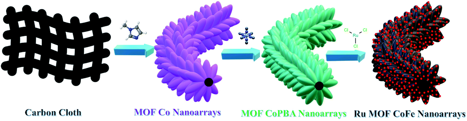
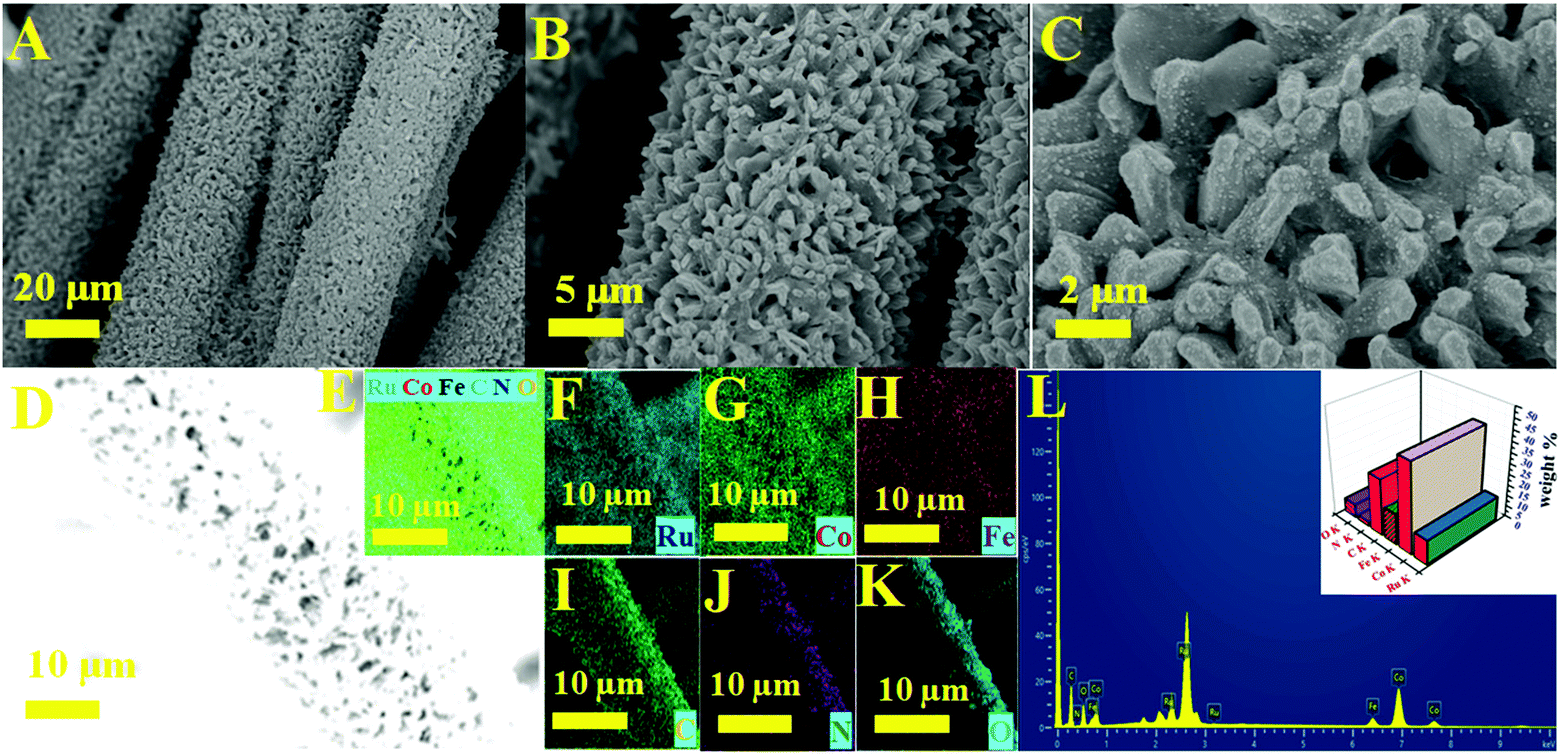
The significant electrocatalytic interface of the electrocatalysts was described in order to validate the successful formation of Ru MOF CoFe nanoarrays on the CC surface. The upper section of Fig. 1 illustrates the Ru MOF CoFe nanoarrays@CC development process. The 2D cobalt-MOF arrays (referred to as MOF-Co) were generated symmetrically on CC in the first stage by the interaction of Co2+ with 2-MeIm in water at ambient temperature. The highly porous Prussian blue analogue Co2[Fe(CN)6] (CoFe(II)-PBA) was formed in the second step by reacting with K3[Fe(CN)6] in an aqueous solution at room temperature for 24 h, using this MOF-Co nanoarray as both the sacrificial template and precursor in the moderately severe integrated component ligand exchange process.31 Third, utilizing RuCl3·3H2O as a source of Ru, the Ru nanoparticles were assembled homogeneously on the surface of MOF CoPBA nanoarrays using a hydrothermal method (Ru MOF CoPBA nanoarrays). Finally, the MOF CoPBA nanoarrays were calcinated in a N2 environment at 350 °C for 2 h, yielding the composite material mesoporous Ru MOF CoFe nanoarrays. Field emission scanning electron microscopy (FESEM) characterization demonstrates the morphology of the Ru MOF CoFe nanoarrays precursor and its analogues. The FESEM image displays that the 2D MOF Co nanoarrays are generated uniformly on CC (Fig. S1A–S1C†). As observed in the enlarged view image shown in Fig. S1C,† an individual MOF nanoarray exhibits a well-defined morphology with a smooth surface and a consistent thickness of 200 nm. These MOF Co nanoarrays are connected to form a three-dimensional network. The EDX spectrum and elemental mapping images indicated the existence and homogenous distribution of Co, C, and O elements on the MOF Co nanoarrays@CC (Fig. S1D–I†). Following the room-temperature post-synthesis ligand exchange reaction, the MOF Co nanoarrays were transformed into mesoporous CoFe(II)-PBA nanoarrays with a rough surface and well-maintained nanoarray shape and vertically stacked basic units. Even during the ligand exchange reaction, relatively tiny ligands may propagate outward from the pure MOF Co nanoarrays, causing the CoFe(II)-PBA shells to gradually expand throughout the whole nanoarrays. As part of this procedure, mesoporous CoFe(II)-PBA with well-defined hollow interiors are furnished.31 As shown in Fig. S2A–S2C,† the EDX and FESEM-mapping techniques were employed to further examine the composition distributions of Co, Fe, C, and N (Fig. S2D–J†). The FESEM images of Ru MOF CoFe nanoarrays indicate a 3D open porous structure with vertically oriented nanoarrays developed on the CC substrate, as shown in Fig. 2A–C. According to the FESEM image shown in Fig. 2B and C, Ru MOF CoFe nanoarrays were largely made up of small Ru particles with irregular shapes and a rough texture. The resulting Ru MOF CoFe nanoarrays certainly preserve their consistently oriented nanoarray structure after calcination in an inert environment, with the exception that the nanoarrays become rougher (Fig. 2C). Furthermore, the related EDX spectrum (Fig. 2L) and elemental mapping show that the elements Ru, Co, Fe, N, C, and O are distributed consistently, demonstrating the effective integration of Ru particles (Fig. 2D–K). The three-dimensional surface topography of the Ru MOF CoFe nanoarrays on CC assessed by atomic force microscopy (AFM) is also shown in Fig. S3,† displaying an absurdly rough texture with vertical elements (dark) and garret regions (bright), resulting in a considerable increase in the number of active sites.
 |
| | Fig. 1 Schematic illustration of the synthesis of Ru MOF CoFe nanoarrays on the CC surface. | |
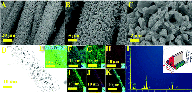 |
| | Fig. 2 (A–C) Low and high magnification FESEM images of Ru MOF CoFe nanoarrays. (D) Electron image and (E) elemental mapping images of Ru (F), Co (G), Fe (H), C (I), N (J), and O (K). (L) EDX spectrum and inset image corresponding to elemental composition images of Ru MOF CoFe nanoarrays. | |
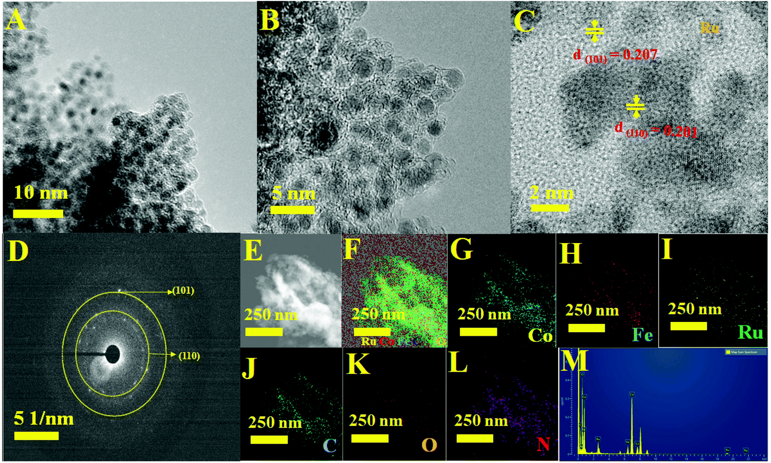
The complete morphological structure of the as-prepared mesoporous Ru MOF CoFe nanoarrays has been investigated using transmission electron microscopy (TEM). TEM images reveal a two-dimensional (2D) nanostructure composed of tiny Ru nanoparticles distributed across the Ru MOF CoFe nanoarrays (Fig. 3A). The nanoarrays are composed of numerous interconnected Ru nanoparticles, as seen in Fig. 3B using high-resolution transmission electron microscopy (HRTEM), with each nanoparticle approximately 2–5 nm in diameter. The high-resolution TEM images (Fig. 3C) of the hierarchical nanostructure demonstrate well-resolved lattice fringes, and the typical interplanar spacings of 0.201 nm and 0.207 nm are well-matched with the (110) and (101) planes of the CoFe nanoparticles, and Ru lattices, respectively.33,34 The selected area electron diffraction (SAED) patterns shown in Fig. 3D were indexed to the (110) and (101) planes of CoFe nanoparticles and Ru lattices for Ru MOF CoFe nanoarrays. To validate the homogenous distribution of each constituent, TEM mapping (Fig. 3E–L) and TEM EDX (Fig. 3M) were used. The EDX mapping images of Ru, Co, Fe, C, O, and N demonstrate that Ru particles were effectively integrated with the MOF CoFe nanoarrays.
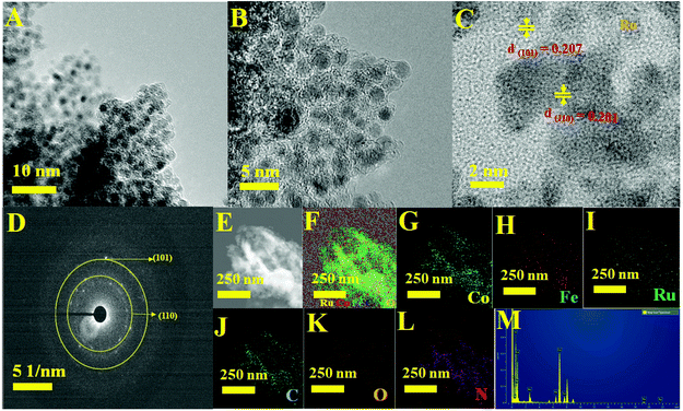 |
| | Fig. 3 (A and B) Different magnification TEM images. (C) High-resolution TEM image with lattice fringe. (D) SAED patterns. (E) STEM image. (F) The corresponding TEM elemental maps of (G) Co, (H) Fe, (I) Ru, (J) C, (K) O and (L) N elements. (M) TEM EDX spectrum of Ru MOF FeCo nanoarrays. | |
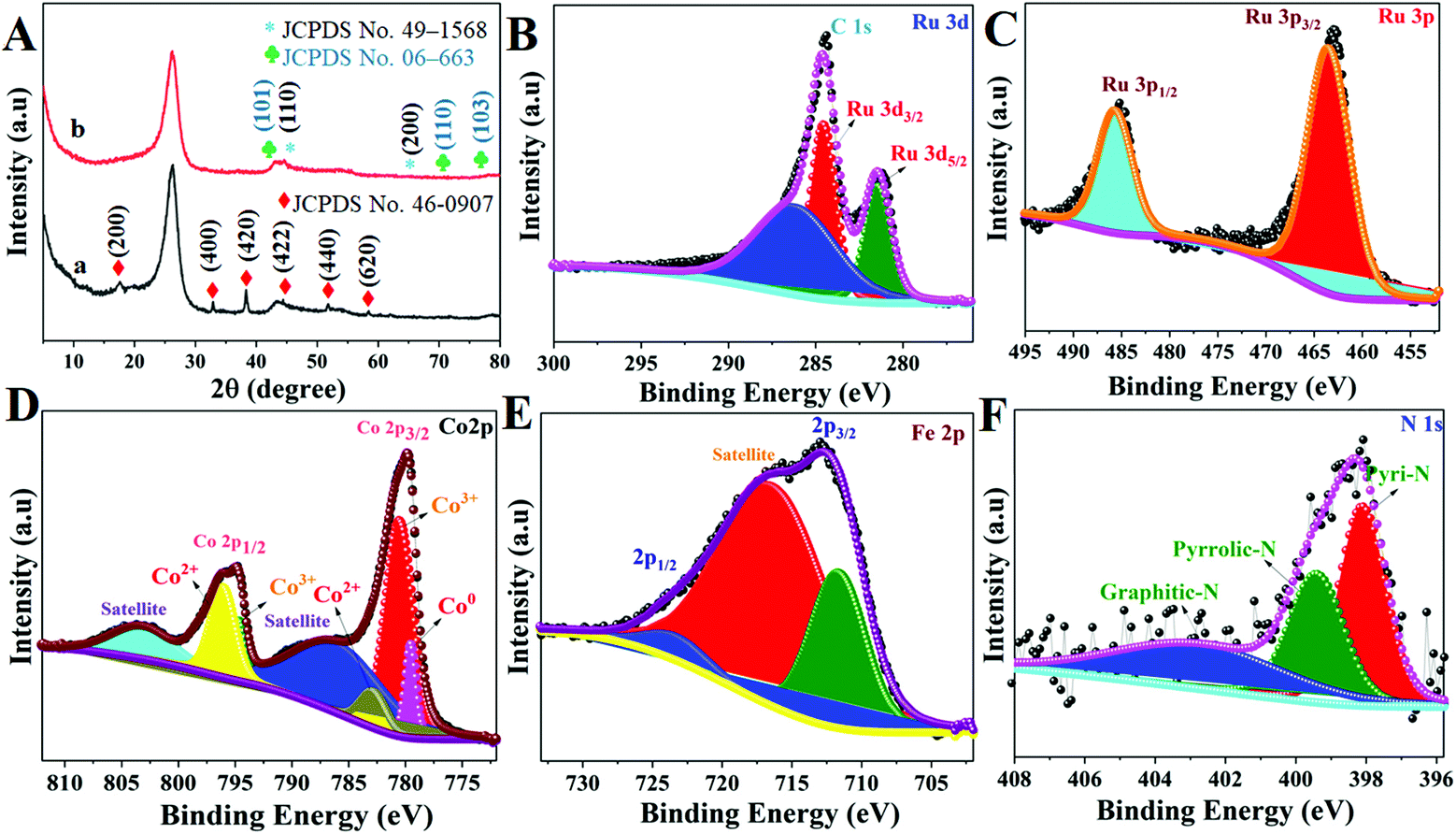
The crystal structure of these Ru MOF CoFe nanoarrays, MOF CoPBA nanoarrays, and MOF Co nanoarrays were further examined using X-ray diffraction (XRD) (Fig. 4). The X-ray diffraction (XRD) pattern of MOF Co nanoarrays fabricated on CC for 1 h is shown in Fig. S4.† The XRD pattern of MOF Co nanoarrays perfectly matches the pattern obtained in previous work, demonstrating that MOF Co nanoarrays are successfully formed on CC.29,30 The XRD data further indicate the effective production of CoFe(II)-PBA. The diffraction patterns strongly suggest that the MOF Co nanoarrays are transformed into CoFe(II)-PBA (Co3[Fe(CN)6], as shown in Fig. 4A(a). Peaks were found at about 2θ values of 17.6° (200), 25.0° (220), 33.4° (400), 38.5° (420), 44.0° (422), 51.0° (440), and 58.5° (620). The observed patterns were strongly correlated with the Co3[Fe(CN)6]·H2O (JCPDS no. 82-2284).32 The powder XRD pattern of Ru MOF CoFe nanoarrays was obtained and is shown in Fig. 4A(b). The prominent diffraction peaks at 2θ values of 44.4° and 65.6° match with the typical (1 1 0) and (2 0 0) planes of CoFe nanoparticles (JCPDS no. 49-1568), which is consistent with the TEM findings.33 Similarly, the observed XRD pattern of these MOF-assisted Ru nanoparticles agrees well with the crystalline character of the Ru nanoparticles. The diffraction peaks are centered at 2θ values of 43.6° and 69.1° which are similar to those found in face-centered cubic (101) and (110) Ru(0) crystals (JCPDS no. 06-663) indicating that Ru might be associated with MOF CoFe nanoarrays to create heterogeneous Ru MOF CoFe nanoarrays entities.34 The surface oxidation states of Ru MOF CoFe nanoarray catalysts can be detected by XPS, which is significant for assessing catalytic activity. The survey XPS spectrum of Ru MOF CoFe nanoarray catalysts is shown in Fig. S5,† indicating the coexistence of Ru, Co, Fe, O, C, and N components. Fig. 4B displays the high-resolution XPS spectrum of the Ru 3d, in which strong binding energy peaks at 284.1 and 280.9 eV can be associated with Ru 3d3/2 and Ru 3d5/2, respectively. Furthermore, the binding energy of Ru is 286.4 eV, which could be allocated to a part of Ru with an oxidation state less than Ru4+ but greater than 0.24 The high-resolution Ru 3p spectrum, as can be seen in Fig. 4C, exhibits two peaks at 485.4 eV (Ru 3p1/2) and 463.2 eV (Ru 3p3/2), which correlate to the metallic form Ru0.34,35 The high-resolution Co 2p XPS segment (Fig. 4D) reveals one spin–orbit pair at 779.2, 780.5, and 782.9 eV corresponding to Co0, Co3+, and Co2+ of Co 2p3/2. The binding energy peaks at 794.43, and 796.17 eV correspond to the Co3+ and Co2+ of Co 2p1/2, respectively.34,36 The high-resolution Fe 2p XPS spectrum shown in Fig. 4E reveals the Fe 2p3/2 and Fe 2p1/2 peaks at 711.5 eV and 723.9 eV, respectively, suggesting the existence of Fe3+, which might be the effect of surface oxidation.37 The N 1s XPS spectrum is shown in Fig. 4F, and it demonstrates that the doped N heteroatoms in carbon appear in three types of moieties including pyridinic N (398.0 eV), pyrrolic N (399.4 eV), and graphitic N. (401.8 eV). These occurrences imply that N atoms are efficiently incorporated into graphitic carbon. Interestingly, pyridinic N is the dominating form that has also been shown to associate with transition metals to increase the ORR and HER.38 As a result, the abundant pyridinic N in Ru-MOF CoFe nanoarrays might have a beneficial impact on the ORR and HER.
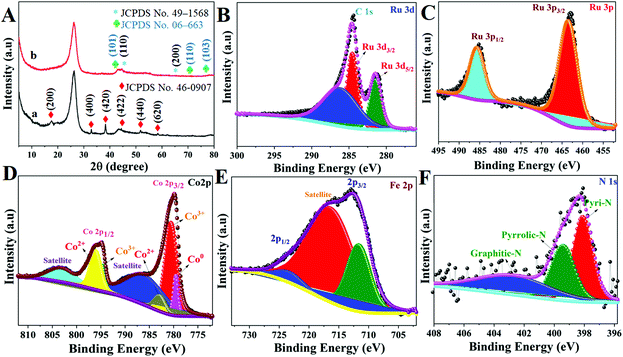 |
| | Fig. 4 (A) XRD patterns of MOF CoPBA nanoarrays@CC (a) and Ru MOF CoFe nanoarrays@CC (b). High-resolution XPS spectra of Ru 3d (B), Ru 3p (C), Co 2p (D), Fe 2p (E) and N 1s (F) of Ru MOF CoFe@CC nanoarrays. | |
3.2. Electrocatalytic performances of Ru MOF CoFe nanoarrays
3.2.1. Electrocatalytic ORR activity of Ru MOF CoFe nanoarrays.
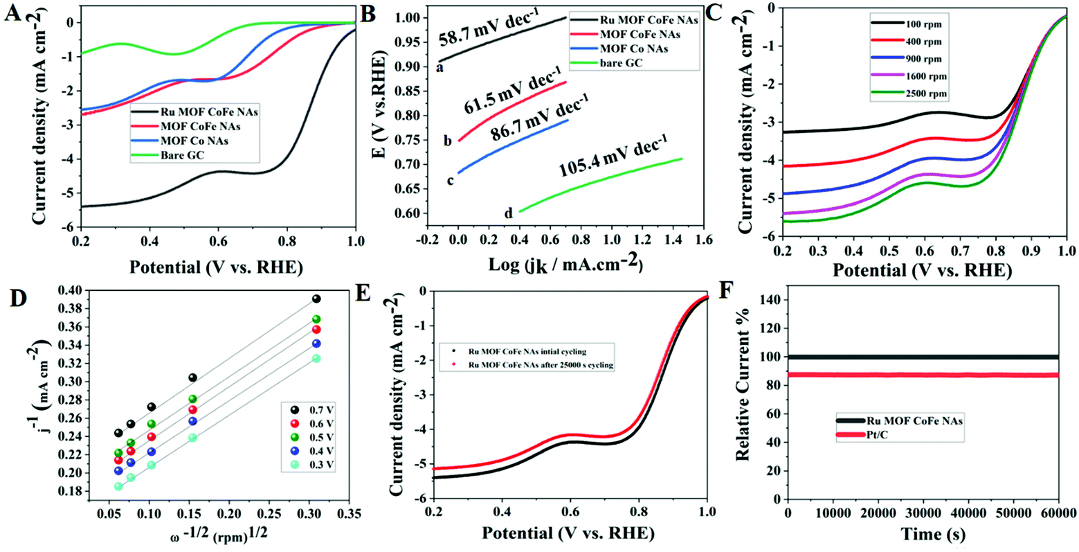
To analyze the electrocatalytic properties of the synthesized Ru-MOF CoFe nanoarrays, the cyclic voltammetry (CV) test was first carried out in a 0.1 M KOH solution saturated with O2 and N2 at a scan rate of 5 mV s−1. MOF CoFe nanoarrays and MOF Co nanoarrays were also used under identical conditions for comparison. In cyclic voltammetry, the oxygen reduction peak of Ru MOF CoFe nanoarrays was observed in the O2-saturated electrolyte, in contrast to the double-layer current recorded when the O2-saturated electrolyte was replaced with the N2 saturated electrolyte (Fig. S6†). It is worth noting that the reduction peak of Ru MOF CoFe nanoarrays is at 0.75 V, which is a more positive value than that of MOF CoFe nanoarrays (0.66 V) and MOF Co nanoarrays (0.62 V), and bare GC (0.55 V). These findings support that Ru MOF CoFe nanoarrays dramatically increased ORR activity. The onset potential, half-wave potential (E1/2), and diffusion limit current are the significant factors for assessing catalytic activity towards the ORR.15 As demonstrated in Fig. 5A, the Ru MOF CoFe nanoarray catalyst exhibits the best catalytic activity with an onset potential of 0.98 V (against RHE) at 0.4 mA cm−2 and a limiting current density of 5.39 mA cm−2 to 0.2 V (1600 rpm). With all other materials, the onset potential and limiting current steadily drop from MOF CoFe nanoarrays (0.85 V, 2.87 mA cm−2@1600 rpm), MOF Co nanoarrays (0.80 V, 2.53 mA cm−2@1600 rpm), and bare GC (0.74 V, 0.875 mA cm−2@1600 rpm). The plateau is inclined in all composite materials, implying a few diffusion barriers or nonuniform distribution of active sites at the electrode.31 The E1/2 values can accommodate the capacity required by a fuel cell cathode while maintaining a high operating voltage to provide excellent energy conversion efficiency. The Ru composite has the highest E1/2 value (0.875 V), suggesting the notably active character of the Ru MOF CoFe nanoarrays in the area of the ORR. These results show that the transition metal and MOFs have a significant impact on the ORR activity within the Ru MOF CoFe nanoarrays. Linear sweep voltammetry (LSV) curves indicate that the Ru MOF CoFe nanoarray catalyst exhibits extremely strong ORR activity and is similar to standard Pt/C catalysts, with an onset potential of around 0.99 V. As a result, the difference in the onset ability between Ru MOF CoFe nanoarrays and conventional Pt/C is just 10 mV. The mass activities are used to additionally analyze the ORR efficiency at 0.8 V vs. RHE, as shown in Fig. S7.† Ru MOF CoFe nanoarrays can offer a mass activity of 24.08 mA mg−1, which is higher than the mass activity of MOF CoFe nanoarrays (11.12 mA mg−1) and MOF Co nanoarrays (10.01 mA mg−1). Tafel slope is a critical parameter in understanding the basic catalytic kinetics of the ORR. As indicated in Fig. 5B, the Tafel slope for Ru MOF CoFe nanoarrays is around 58.7 mV dec−1, which is less than that of MOF CoFe nanoarrays (86.7 mV dec−1), MOF Co nanoarrays (105.4 mV dec−1), and Pt/C (56.9 mV dec−1) (Fig. S8†). The enhanced reaction kinetics are indicated by a lower Tafel slope of the MOF CoFe nanoarrays. As shown in Fig. 5C, LSV curves were obtained at various rotational speeds ranging from 100 to 2500 rpm in order to completely investigate the catalytic kinetics of the Ru MOF CoFe nanoarrays. As shown in Fig. S9,† MOF CoFe nanoarrays, MOF Co nanoarrays, bare GCE, and Pt/C (Fig. S10†) were also evaluated under the same conditions for comparison. According to the Koutecky–Levich (K–L) equation, the estimated electron transfer number (n) of the Ru MOF CoFe nanoarrays is around 3.93 (Fig. 5D). This is comparable to Pt/C (3.97, Fig. S11†), indicating that the ORR on the Ru MOF CoFe nanoarrays follows the 4e− pathway. The stability of advanced catalysts is an important factor to consider when evaluating their implementation in practical applications. Even after 25000 cycles of scanning, there is a modest negative shift of the E1/2 (ca. 14 mV) on the LSV curves, as shown in Fig. 5E, implying that the Ru MOF CoFe nanoarrays are more stable. Additionally, the corresponding chronoamperometric curve was also recorded at a rotation rate of 1600 rpm and a potential of 0.6 V was used to examine the long-term durability. After 50000 s of continuous mode, the current for the Ru MOF CoFe nanoarrays sustains 96% of its initial value (Fig. 5F), but the current for the Pt/C retains only 85% of its initial value under identical circumstances, illustrating the higher stability of the Ru MOF CoFe nanoarrays.
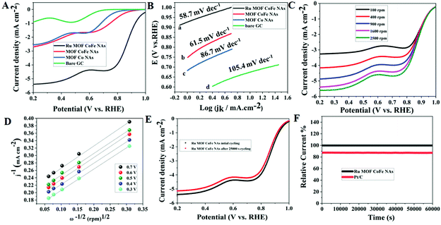 |
| | Fig. 5 (A) LSV curves of the various catalysts in O2-saturated 0.1 M KOH solution. (B) Corresponding Tafel plots for various catalysts. (C) LSV curves of the Ru MOF CoFe nanoarray catalyst in O2-saturated 0.1 M KOH solution at different rotation rates. (D) K–L plots measured at various potential values from 0.3 to 0.7 V vs. RHE. (E) Polarization curves of Ru MOF CoFe nanoarray catalyst before and after 25000 s. (F) Long-term stability studies of Ru MOF CoFe nanoarrays and Pt/C catalyst in O2-saturated 0.1 M KOH. | |
3.2.2. Electrocatalytic HER activity of Ru MOF CoFe nanoarrays.
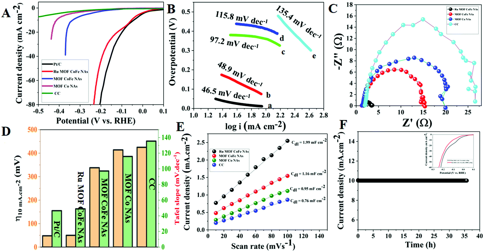
The electrocatalytic HER performance was evaluated in 1 M KOH solution using a typical three-electrode system. All potentials in this study are calibrated to the reversible hydrogen electrode (RHE). Fig. 6A depicts the relevant polarization curves with iR rectification for Ru MOF CoFe nanoarrays, MOF CoFe nanoarrays, MOF Co nanoarrays, bare CC, and commercial Pt/C. The LSV curve of Ru MOF CoFe nanoarrays clearly illustrates their excellent HER activity, which is comparable to the commercial Pt/C@CC catalyst. The fabricated Ru MOF CoFe nanoarray catalyst exhibits a low overpotential of only 50 mV at a derived current density of 10 mA cm−2, which is very close to Pt/C@CC (48 mV). This measured overpotential for the HER is lower than that found in the other MOF-CoFe nanoarrays (338 mV@10 mA cm−2), MOF-Co nanoarrays (414 mV@10 mA cm−2), and bare CC (425 mV@5 mA cm−2). The Tafel slope is used to examine the rate-determining step (RDS) to gain a better understanding of the catalytic kinetics of the HER mechanism.4Fig. 6B displays the Tafel plots generated from the LSV polarization curves. It can be found that Ru-MOF CoFe nanoarray catalyst displays a lower Tafel slope of 58.9 mV dec−1, while MOF-CoFe nanoarrays, MOF-Co nanoarrays, and bare CC exhibited Tafel slopes of 97.2 mV dec−1, 115.8 mV dec−1, and 135.4 mV dec−1 which were slightly higher than the value of 51.5 mV dec−1 of Pt/C. According to the previous finding, the Tafel slope indicates that the HER on Ru MOF CoFe nanoarray catalyst adopts the Volmer–Heyrovsky mechanism, and subsequently, the reaction rate is determined by the electrodesorption step (H2O discharge and desorption of H from the Ru MOF CoFe nanoarray surface).7,19 In addition, the electrochemical impedance spectroscopy (EIS) method was then used to investigate the electrode kinetics of the synthesized samples (Fig. 6C). The charge-transfer resistance (Rct) of materials assessed by EIS revealed that Ru-MOF CoFe nanoarrays show a lower Rct (1.80 Ω) than MOF-CoFe nanoarrays (14.55 Ω), MOF-Co nanoarrays (18.98 Ω), and bare CC (25.80 Ω), indicating their high conductivity among prepared materials. The smaller charge-transfer resistance indicates that electron transport is particularly efficient and that HER kinetics is anticipated at the electrode and electrolyte interface.12Fig. 6D indicates that the Ru MOF CoFe nanoarrays had significantly better catalytic performance than the other catalysts. Besides, a CV technique was then utilized to determine the ECSA by measuring the double-layer capacitance (Cdl) (Fig. S12†). As demonstrated in Fig. 6E, Ru MOF CoFe nanoarrays show a Cdl of 1.99 mF cm−2, which is greater than MOF CoFe nanoarrays (1.16 mF cm−2) and MOF-Co nanoarrays (0.95 mF cm−2) and bare CC (0.76 mF cm−2). The considerable ECSA implies that the Ru MOF CoFe nanoarray catalyst possesses superior HER activity. Chronoamperometry was utilized to evaluate the electrocatalytic durability of the Ru-MOF CoFe nanoarray catalyst at a constant potential of 50 mV in 1 M KOH (Fig. 6F). This catalyst remained stable for more than 35 h with a relatively constant current density. To further assess the cyclic stability of Ru MOF CoFe nanoarrays, cyclic voltammetry (CV) was performed 10000 times (inset in Fig. 6F). The polarization curves reveal a slight drop in the overpotential with a current density of 10 mA cm−2 in the before and after 10000 CV scans.
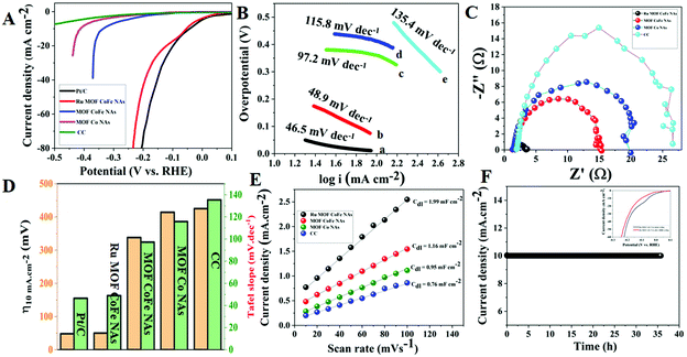 |
| | Fig. 6 (A) LSV curves of different HER electrocatalysts at the scan rate of 5 mV s−1 in 1.0 M KOH solution. (B) Tafel plots of corresponding electrocatalysts. (C) EIS curves of various HER electrocatalysts. (D) Bar graph for overpotential versus Tafel slope of the as-synthesized electrocatalysts. (E) Cdl for Ru-MOF CoFe nanoarrays and other comparative electrocatalysts. (F) CA stability curve of the Ru-MOF CoFe nanoarrays at an overpotential of 50 mV and inset graph cyclic stability curves before and after 10000 CV cycles. | |
3.2.3. Electrocatalytic OER activity of Ru MOF CoFe nanoarrays.
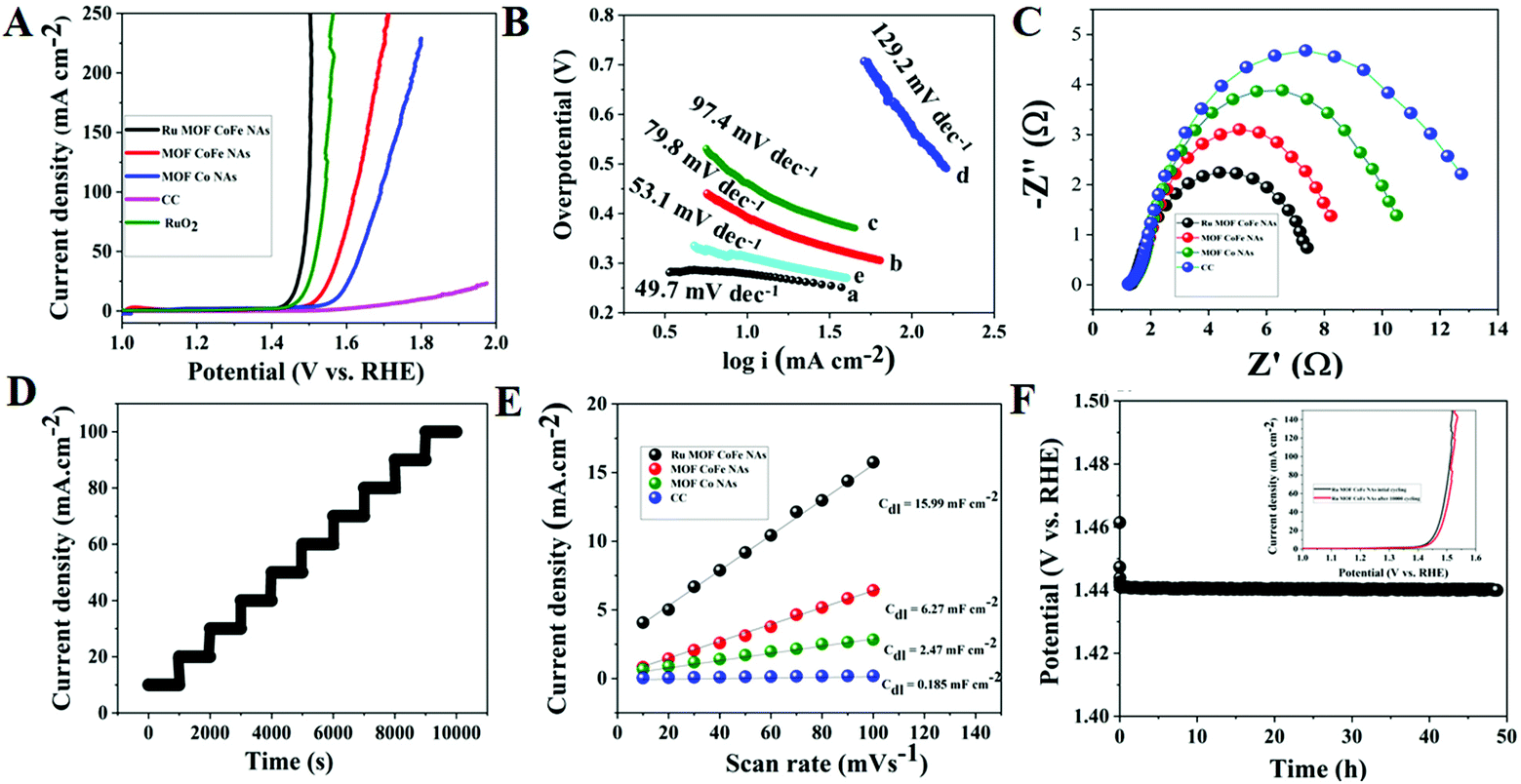
The OER electrocatalytic activity of Ru-MOF CoFe nanoarrays was further investigated in 1 M KOH solutions using a conventional three-electrode method. The OER activities of discrete MOF-CoFe nanoarrays and MOF-Co nanoarrays, bare CC, and RuO2@CC were also investigated for comparison. The LSV curves reveal that the Ru MOF CoFe nanoarrays have the lowest OER onset potential and the maximum current density among all materials, as illustrated in Fig. 7A, showing superior catalytic activity. On the other hand, the electrocatalytic OER activity of Ru MOF CoFe nanoarrays is superior to that of RuO2@CC as benchmark electrocatalysts. It could also easily achieve a geometrical current density (j) of 10 mA cm−2 at a smaller overpotential of 220 mV, which is 20 mV lower than that of the precious RuO2@CC (240 mV) but significantly exceeds the overpotential values of MOF-CoFe nanoarrays (290 mV), MOF-Co nanoarrays (340 mV), and bare CC (570 mV) at the same current density. This demonstrates that significant electrocatalytic OER activity is achieved in Ru MOF CoFe nanoarrays via integrity coupling and pragmatic unsaturated site and pore-inducing MOF crystallization and ruthenium incorporation.18 It emphasizes the importance of integrity coupling, pragmatic unsaturated sites, pore-inducing MOF architecture, and ruthenium integration for obtaining significant electrocatalytic OER activity in Ru-MOF CoFe nanoarrays.18,19 By plotting overpotential (η) vs. log(j), the electrocatalytic OER kinetics are investigated over their respective Tafel plots obtained from the polarization curves (j) (Fig. 7B). The Tafel slope of Ru-MOF CoFe nanoarrays was 49.7 mV dec−1, compared to 79.8, 97.4, and 129.2 mV dec−1 for MOF-CoFe nanoarrays, MOF-Co nanoarrays, and bare CC, respectively, indicating plausible reaction kinetics toward the OER. The Tafel slope of Ru MOF CoFe nanoarrays is particularly lower than that of RuO2@CC (51.8 mV dec−1). Furthermore, as proven by EIS, the increased activity of Ru MOF CoFe nanoarrays contrasted to those of MOF-CoFe nanoarrays, MOF-Co nanoarrays, and bare CC and can be attributed to their higher conductivity (Fig. 7C). According to Nyquist plots, it possesses a significantly low charge transfer resistance, which is especially important given the following 3D interconnected structural arrangement.18 This guarantees high conductivity over the CC surface to the Ru MOF CoFe nanoarrays and effective charge transfer kinetics throughout the electrocatalytic processes. The multi-potential operation curve for the Ru MOF CoFe nanoarray catalyst is illustrated in Fig. 7D, with a continuously increasing constant potential from 0.24 to 0.40 V with a potential of 0.02 V rise every 1000 s without iR rectification. At a starting potential of 0.24 V, the current density instantly balances off at 10 mA cm−2 and is maintained static for the next 1000 seconds, confirming the exceptional mass transport properties and mechanical stability. To acquire a better knowledge of performances of various catalysts, their intrinsic electrocatalytic capabilities are fully investigated by assessing electrochemically active surface areas (ECSAs). To evaluate the ECSA, double-layer capacitances (Cdl) of the electrocatalysts are measured using cyclic voltammetry (Fig. S13†). As depicted in Fig. 7E, the Ru-MOF CoFe nanoarrays exhibit the largest active surface area with a Cdl of 44 mF cm−2, which is more than the MOF CoFe nanoarrays, MOF Co nanoarrays, and CC respectively. This is because the highly permeable and 3D interconnected structure provides the catalyst with a more accessible catalytic surface, confirming its potential OER capabilities. A chronopotentiometry (CP) study at 10 mA cm−2 was used to determine the durability of the electrocatalyst (Fig. 7F). The Ru MOF CoFe nanoarray catalyst working overpotential after 35 h of testing denotes that the catalyst was more stable in the alkaline medium. Importantly, after 10000 cycles, the Ru MOF CoFe nanoarray catalyst followed a similar polarization curve to the initial one, with almost minimal deterioration of anodic current density (inset Fig. 7F).
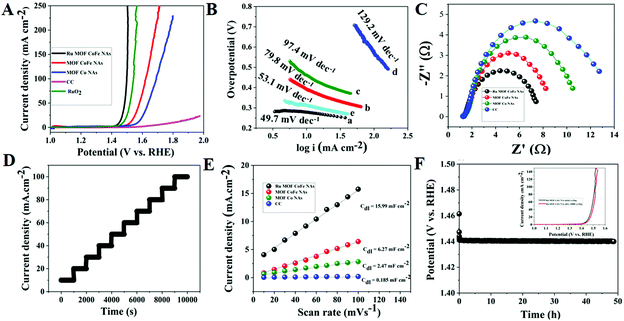 |
| | Fig. 7 (A) LSV curves of different OER electrocatalysts at a scan rate of 5 mV s−1 in 1.0 M KOH alkaline solution. (B) Tafel plots of corresponding electrocatalysts. (C) EIS curves of various OER electrocatalyst, (D) multi steps CP curves of Ru MOF CoFe nanoarray electrocatalysts. (E) Cdl for Ru MOF CoFe nanoarrays and other comparative electrocatalysts. (F) CP stability curve of the Ru MOF CoFe nanoarrays at a constant current density of 10 mA cm−2 and inset graph cyclic stability curves before and after 10000 CV cycles. | |
3.2.4. Overall electrocatalytic water splitting of Ru MOF CoFe nanoarrays.
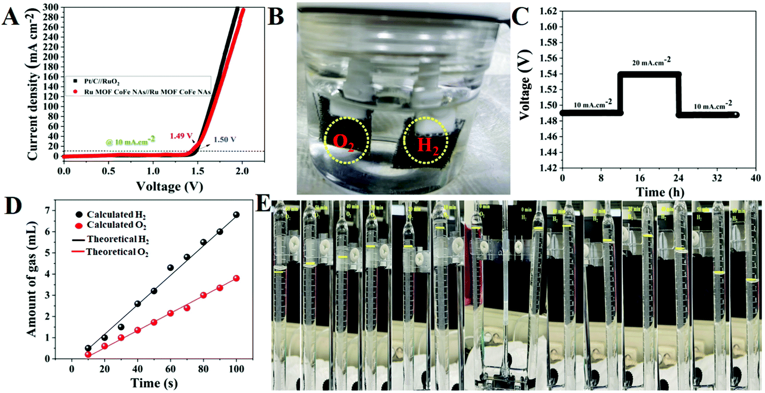
Based on the optimistic HER and OER behaviors of the Ru MOF CoFe nanoarrays, it is presumed that the Ru MOF CoFe nanoarrays will be a suitable bifunctional electrocatalyst for overall water splitting in a basic medium. As a result, an electrolyzer is constructed by employing the Ru MOF CoFe nanoarray electrodes as both the anode and cathode in 1 M KOH. As a comparison, an alkaline electrolyzer built with Pt/C@CC as the cathode and RuO2@CC as the anode (Pt/C@CC (−) & RuO2@CC (+)) was also investigated. The total water splitting performance of a two-electrode device is depicted in Fig. 8A. Notably, Ru-MOF CoFe nanoarray pair yields outstanding catalytic activity, as evidenced by the requirement of a low cell voltage of 1.49 V to achieve a current density of 10 mA cm−2 which is 10 mV lower than that estimated for the Pt/C@CC (−) and RuO2@CC (+) cell (1.50 V). At 1.49 V, rapidly formed hydrogen and oxygen bubbles may be seen on the anode and cathode, as seen in Fig. 8B. Meanwhile, the long-term electrochemical durability of the Ru-MOF CoFe nanoarray pair is also being examined utilizing chronopotentiometry testing with consecutive current densities of 10, 20, and 10 mA cm−2 and analyzing fluctuations in the original resulting potentials after 35 h of uninterrupted electrolysis (Fig. 8C). The Ru MOF CoFe nanoarray pair demonstrates outstanding long-term stability for total water splitting, revealing that it is not only extremely active but also has a very reliable overall water spotting performance. The Faradaic efficiency of the Ru MOF CoFe nanoarray catalyst was determined by correlating the quantity of empirically observed gas with the quantity of theoretically estimated gas. Using a typical runoff technique, the experimentally generated gas (H2 and O2) was measured in a U-type electrolytic cell with a unique anode and cathode. The homemade U-type electrolytic cell for overall water splitting, as illustrated in Fig. S14† used Ru-MOF CoFe nanoarrays on both sides as the anode and cathode. For every 10 minutes, the volume of O2 and H2 released at 20 mA cm−2 was measured by monitoring the measurement tube. The experimentally measured gas, both O2 and H2 produced at the anode and cathode, as shown in Fig. 8D, was perfectly consistent with the theoretical values, exhibiting almost 99% Faradaic efficiency for both the OER and HER. The digital photographic images of the U-type electrolytic cells are displayed in Fig. 8E and the volume ratio of O2 to H2 was changing approximately 0.5 mL at 10, 20, 30, 40, 50, and 60 minutes, respectively. Furthermore, when compared to the more difficult chemical synthesis procedures detailed in Table S1,† designing and implementing these electrocatalysts is quite inexpensive.
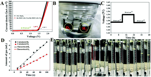 |
| | Fig. 8 (A) Two electrode LSV curves of the Ru MOF CoFe nanoarrays (+) || Ru MOF CoFe nanoarrays (−) and Pt/C@CC (−) || RuO2@CC (+) devices in 1.0 M KOH. (B) Digital photographic images of the electrochemical water splitting cell. (C) Time dependence voltage curves under constant current densities of 10 and 20 mA cm−2 over 35 h of continuous performance for the Ru MOF CoFe nanoarrays (+) || Ru MOF CoFe nanoarray (−) cell. (D) Amounts of gas were theoretically measured and experimentally measured for overall water splitting at 20 mA cm−2. (E) The digital photographic images allow for the monitoring of H2 and O2 production during water electrolysis. The yellow mark indicates that oxygen and hydrogen gases were collected at various time intervals. | |
3.2.5. Seawater electrocatalytic activity of Ru MOF CoFe nanoarrays.
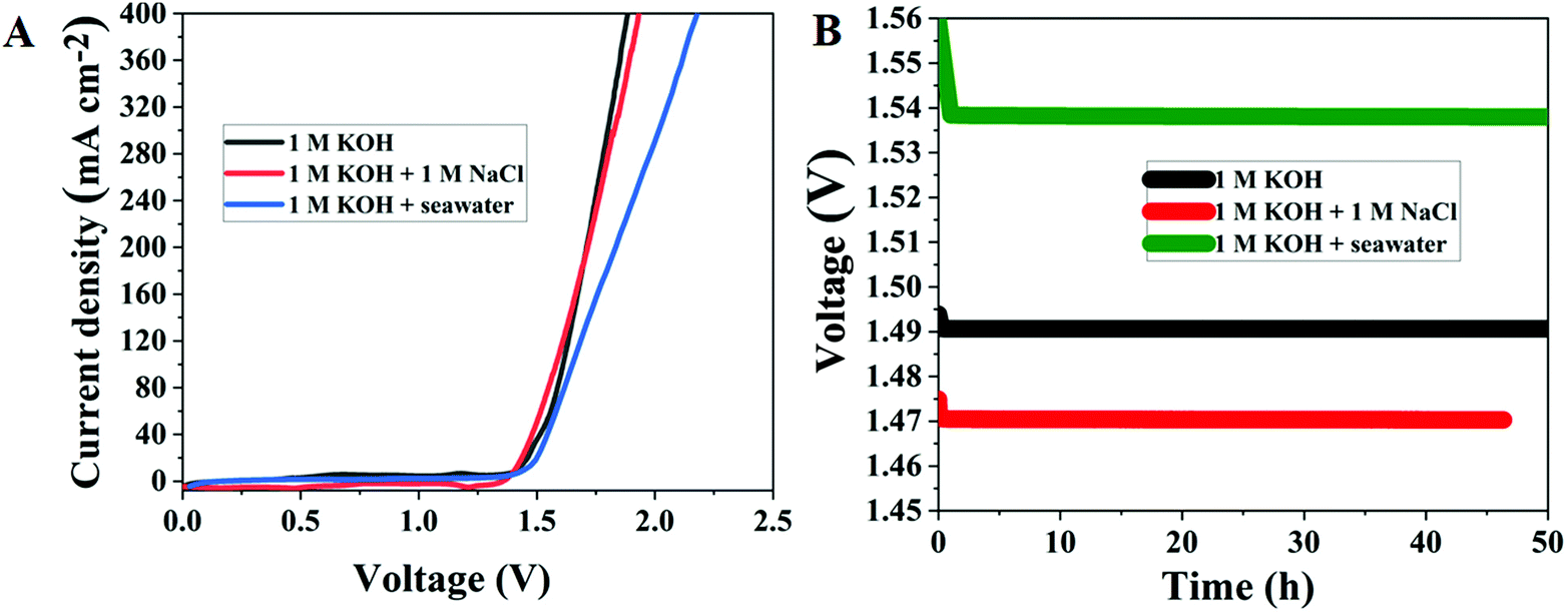
Motivated by the exceptional electrocatalytic activity of Ru MOF CoFe nanoarrays for overall water splitting reactions, artificial and seawater splitting are then used in a two-electrode configuration with the same electrolyzer. This catalyst manufacturing approach is rapid, and low-cost, with little need for experimental equipment and the ability to attain production potential, lowering production costs significantly. Furthermore, in order to investigate whether the Ru-MOF CoFe nanoarray catalyst can be employed for large-scale industrial hydrogen evolution, and oxygen evolution, the catalyst was directly used for seawater electrolysis. Accordingly, the performance of a 10 mg cm−2 Ru MOF CoFe nanoarrays coated CC-based catalyst toward the HER in 1.0 M KOH electrolyte was assessed. Motivated by the exceptional electrocatalytic activity of Ru MOF CoFe nanoarrays for overall water splitting reactions, artificial and seawater splitting are then used in a two-electrode configuration with the same electrolyzer (Fig. 9A). In alkaline artificial seawater, the Ru MOF CoFe nanoarray electrolyzer needed cell voltages of 1.47 V to obtain current densities of 10 mA cm−2, which was lower than that in 1 M KOH. This is owing to the fact that the addition of NaCl enhances the ionic conductivity of the electrolyte.39 In alkaline natural seawater, the electrocatalytic activity of the as-fabricated electrolyzer is slightly reduced, achieving current densities of 10 mA cm−2 at 1.54 V. The observed current densities of the electrolyzer continue to progress in 1 M KOH and alkaline natural and simulated seawater, as shown in Fig. 9B, exhibiting great durability. After 50 h of operation in alkaline natural seawater, the current density barely decreases by 0.02 mV, demonstrating strong potential for hydrogen generation via seawater splitting. The minor decrease in electrocatalytic activity most likely leads to the formation and deposition of metal hydroxides at the cathode.39 Because of all these difficulties, pure saline water generated with 1 M NaCl is commonly used for laboratory investigations.
 |
| | Fig. 9 (A) LSV curves of Ru MOF CoFe nanoarray performance in artificial seawater and natural seawater electrolysis. (B) Long-term stability measurements of Ru MOF CoFe nanoarrays performed at a constant current cell voltage in different electrolytes. | |
3.2.6. Post characterization and mechanistic insight into Ru MOF CoFe nanoarrays.
According to the findings, the Ru MOF CoFe nanoarray catalyst is an excellent choice for water electrolysis, with increased activity and long-term stability. Furthermore, FESEM, TEM, XRD, and XPS were used to study the morphology, crystal structure, and element valence states of the Ru MOF CoFe nanoarray electrode after total water splitting. The XRD analyses of the post-OER catalyst clearly demonstrate that the surface is partially changed into the oxyhydroxide phase, revealing a surface composition change under the oxidative conditions of the OER.17 The XRD results show that the Ru MOF CoFe nanoarrays were completely preserved after the overall water splitting reaction, with no new XRD diffraction peaks detected, demonstrating their better stability for water splitting (Fig. S15†). The XPS survey spectrum is shown in Fig. S16A,† which shows the existence of Ru, Co, Fe, C, and O in the samples. In addition, the high-resolution Co 2p3/2 spectrum (Fig. S16B†) with a dominant binding energy peak at 780.1 eV may be correlated to the Co species in CoOOH species.29 The high-resolution Fe 2p3/2 spectrum (Fig. S16C†) with a wide peak located at around 711.8 eV may be ascribed to Fe species in FeOOH.31 Peaks at 486.1 and 464.1 eV in the high-resolution Ru 3p XPS spectra (Fig. S16D†) were attributed to oxidized Ru species, which might explain the slight reduction in electrocatalytic performance.35 The FESEM images of the Ru MOF CoFe nanoarray catalyst after electrochemical cycling show that the CC was entirely encased in a layer of Ru-MOF CoFe nanoarrays (Fig. S17†), proving no noticeable change in surface chemical components which is supported by HRTEM of the post catalytic sample (Fig. S18†).
We also undertook electronic structural investigations, such as density of states (DOS), to better understand the synergistic effects of Ru incorporation and MOF CoFe nanoarrays on electrochemical performance and intrinsic activity. To build rational models, the Ru incorporation is specified as MOF CoFe nanoarrays, as illustrated in Fig. S19.† In comparison with pristine CoFe, the Ru incorporated CoFe has a more delocalized density of states (DOS) distribution and a minimum energy level of the d-band center of Co and Fe atoms.40 It is important to keep in mind that the low spin state of pure CoFe is more stable than the high spin state, while the high spin state is more stable than the low spin state of Ru-integrating CoFe. The downshift of the Co and Fe d-band centers in Ru-integrating CoFe compared to CoFe is beneficial for reducing the binding capacity of the *OH, *O, and *OOH intermediates on the active site and, as a result, boosting OER, HER, and ORR activity.40 The presence of Ru species can alter the spin states of Co and Fe atoms in CoFe, promoting the catalytic capabilities of the Co and Fe centers.41,42 Furthermore, a theoretical study reveals that Ru integration can increase electron delocalization, as seen by Co and Fe atom spin state changes and thus, Ru integration not only provides new catalytic active sites (Ru site) but also boosts the activity of existing sites. Additionally, the significant hybridization of Co 3d, Fe 3d, and Ru 3d implies that Ru-MOF CoFe nanoarrays possess excellent electrical conductivity.35 The observations are mostly consistent with the EIS results, which show that the presence of Ru atoms increases the electrical conductivity of Ru MOF CoFe nanoarrays and speeds up electron transport in the electrocatalyst reaction.23 According to the abovementioned experimental observations and computational methods, the outstanding catalytic activity and distinct stability of Ru-MOF CoFe nanoarrays for the HER, OER, ORR, and total water splitting under all circumstances are mostly ascribed to the following circumstances: (1) the inclusion of Ru may affect the electronic structure and d states of CoFe, boosting its catalytic activity sites and facilitating OH− entrapment and O2 desorption. (2) The abundance of Ru species in CoFe may result in strong electron couplings, resulting in enhanced conductivity. (3) Another benefit of the construction of 2D nanoarrays is that they provide the reactants with more accessible active sites, which dramatically improve electron transfer and mass transport during electrochemical reactions. (4) The interfacial synergy effect was efficiently created by the multimodal nanointerface within the heterostructured Ru MOF CoFe nanoarrays, boosting water electrolysis even further.
4. Conclusions
In summary, we designed a robust room-temperature method for developing porous Ru-MOF CoFe nanoarrays that includes a moderate post-synthetic ligand exchange reaction followed by a simple calcination process. Surprisingly, Ru integration and chemical conversion considerably caused efficient interface architecture, generating high-quality Ru-MOF CoFe nanoarrays. Because of their excellent structural and functional features, ideal electronic states, considerable interfacial synergistic activity, and porosity, the nanocatalysts might be desirable electrocatalysts for the OER, HER, ORR, and overall water splitting. Under basic conditions, Ru-MOF CoFe nanoarrays offer an exceptionally low overpotential and a modest Tafel slope. In a nutshell, the Ru MOF CoFe nanoarrays may be employed in an alkaline electrolytic cell and also work as an excellent bifunctional electrocatalyst for total water splitting and seawater electrolysis. Given the strong catalytic activity of the as-synthesized catalyst and the effortlessness of the preparation process, this study significantly contributes to the formation of the hydrogen fuel cell and presents a new avenue for meticulous processing and utilization of saltwater electrolysis. Importantly, the suggested cooperative methodology is shown to be broad enough for the emergence of unique interlinked metal–organic transition metals, which might be used for a variety of possible applications such as lithium–air and zinc–air batteries.
Conflicts of interest
There are no conflicts to declare.
Acknowledgements
The authors acknowledge the Basic Science Research Program through the National Research Foundation of Korea (NRF) grant funded by the Ministry and Education (2021R1/1AA0104667811). This work is supported by the BK21 FOUR Program by Jeonbuk National University Research Grant.
Notes and references
- Y. Shi and B. Zhang, Chem. Soc. Rev., 2016, 45, 1529–1541 RSC.
- T. Wang, X. Wang, Y. Liu, J. Zheng and X. Li, Nano Energy, 2016, 22, 111–119 CrossRef CAS.
- P. Zhai, M. Xia, Y. Wu, G. Zhang, J. Gao, B. Zhang, S. Cao, Y. Zhang, Z. Li, Z. Fan, C. Wang, X. Zhang, J. T. Miller, L. Sun and J. Hou, Nat. Commun., 2021, 12, 1–11 CrossRef PubMed.
- C. Liang, P. Zou, A. Nairan, Y. Zhang, J. Liu, K. Liu, S. Hu, F. Kang, H. J. Fan and C. Yang, Energy Environ. Sci., 2020, 13, 86–95 RSC.
- L. Yu, L. Wu, B. McElhenny, S. Song, D. Luo, F. Zhang, Y. Yu, S. Chen and Z. Ren, Energy Environ. Sci., 2020, 13, 3439–3445 RSC.
- L. Li, B. Wang, G. Zhang, G. Yang, T. Yang, S. Yang and S. Yang, Adv. Energy Mater., 2020, 10, 2001600 CrossRef CAS.
- Y. Pei, S. Guo, Q. Ju, Z. Li, P. Zhuang, R. Ma, Y. Hu, Y. Zhu, M. Yang, Y. Zhou, J. Shen and J. Wang, ACS Appl. Mater. Interfaces, 2020, 12, 36177–36185 CrossRef CAS PubMed.
- J. Lim, D. Park, S. S. Jeon, C. W. Roh, J. Choi, D. Yoon, M. Park, H. Jung and H. Lee, Adv. Funct. Mater., 2018, 28, 1704796 CrossRef.
- P. Jiang, Y. Yang, R. Shi, G. Xia, J. Chen, J. Su and Q. Chen, J. Mater. Chem. A, 2017, 5, 5475–5485 RSC.
- Y. Feng, C. Yang, W. Fang, B. Huang, Q. Shao and X. Huang, Nano Energy, 2019, 58, 234–243 CrossRef CAS.
- X. Li, J. Wei, Q. Li, S. Zheng, Y. Xu, P. Du, C. Chen, J. Zhao, H. Xue, Q. Xu and H. Pang, Adv. Funct. Mater., 2018, 28, 1800886 CrossRef.
- S. H. Chae, A. Muthurasu, T. Kim, J. S. Kim, M. S. Khil, M. Lee, H. Kim, J. Y. Lee and H. Y. Kim, Appl. Catal., B, 2021, 293, 120209 CrossRef CAS.
- Y. Li, M. Cui, Z. Yin, S. Chen and T. Ma, Chem. Sci., 2020, 11, 11646–11671 RSC.
- S. T. Rahman, K. Y. Rhee and S. J. Park, Nanotechnol. Rev., 2021, 10, 137–157 CrossRef CAS.
- S. Surendran, S. Shanmugapriya, A. Sivanantham, S. Shanmugam and R. Kalai Selvan, Adv. Energy Mater., 2018, 8, 1800555 CrossRef.
- A. Sivanantham, P. Ganesan, A. Vinu and S. Shanmugam, ACS Catal., 2020, 10, 463–493 CrossRef CAS.
- J. Zhang, J. Liu, L. Xi, Y. Yu, N. Chen, S. Sun, W. Wang, K. M. Lange and B. Zhang, J. Am. Chem. Soc., 2018, 140, 3876–3879 CrossRef CAS PubMed.
- P. Li, M. Wang, X. Duan, L. Zheng, X. Cheng, Y. Zhang, Y. Kuang, Y. Li, Q. Ma, Z. Feng, W. Liu and X. Sun, Nat. Commun., 2019, 10, 1711 CrossRef PubMed.
- Y. Lin, M. Zhang, L. Zhao, L. Wang, D. Cao and Y. Gong, Appl. Surf. Sci., 2021, 536, 147952 CrossRef CAS.
- J. Xu, T. Liu, J. Li, B. Li, Y. Liu, B. Zhang, D. Xiong, I. Amorim, W. Li and L. Liu, Energy Environ. Sci., 2018, 11, 1819–1827 RSC.
- J. Zhang, X. Xu, L. Yang, D. Cheng and D. Cao, Small Methods, 2019, 3, 1900653 CrossRef CAS.
- J. Su, Y. Yang, G. Xia, J. Chen, P. Jiang and Q. Chen, Nat. Commun., 2017, 8, 14969 CrossRef PubMed.
- D. Chen, Z. Pu, R. Lu, P. Ji, P. Wang, J. Zhu, C. Lin, H. W. Li, X. Zhou, Z. Hu, F. Xia, J. Wu and S. Mu, Adv. Energy Mater., 2020, 10, 2000814 CrossRef CAS.
- M. Kuang, Y. Wang, W. Fang, H. Tan, M. Chen, J. Yao, C. Liu, J. Xu, K. Zhou and Q. Yan, Adv. Mater., 2020, 32, 2002189 CrossRef CAS PubMed.
- S. Zheng, Y. Sun, H. Xue, P. Braunstein, W. Huang and H. Pang, Natl. Sci. Rev., 2021, nwab197 CrossRef.
- A. Muthurasu, A. P. Tiwari, K. Chhetri, B. Dahal and H. Y. Kim, Nano Energy, 2021, 88, 106238 CrossRef CAS.
- T. Mukhiya, A. Muthurasu, A. P. Tiwari, K. Chhetri, S. H. Chae, H. Kim, B. Dahal, B. M. Lee and H. Y. Kim, ACS Appl. Mater. Interfaces, 2021, 13, 23732–23742 CrossRef CAS PubMed.
- W. Li, X. Guo, P. Geng, M. Du, Q. Jing, X. Chen, G. Zhang, H. Li, Q. Xu, P. Braunstein and H. Pang, Adv. Mater., 2021, 33, 2105163 CrossRef CAS PubMed.
- A. Muthurasu, G. P. Ojha, M. Lee and H. Y. Kim, J. Phys. Chem. C, 2020, 124, 14465–14476 CrossRef CAS.
- A. Muthurasu, V. Maruthapandian and H. Y. Kim, Appl. Catal., B, 2019, 248, 202–210 CrossRef CAS.
- A. Muthurasu, B. Dahal, T. Mukhiya, K. Chhetri and H. Y. Kim, ACS Appl. Mater. Interfaces, 2020, 12, 41704–41717 CrossRef PubMed.
- G. Zhang, Y. Li, X. Xiao, Y. Shan, Y. Bai, H. G. Xue, H. Pang, Z. Tian and Q. Xu, Nano Lett., 2021, 21, 3016–3025 CrossRef CAS PubMed.
- Y. Fan, Y. Sun, X. Zhang and J. Guo, Chem. Eng. J., 2021, 426, 131922 CrossRef CAS.
- A. Biswas, S. Paul and A. Banerjee, J. Mater. Chem. A, 2015, 3, 15074–15081 RSC.
- D. Chen, R. Lu, Z. Pu, J. Zhu, H. W. Li, F. Liu, S. Hu, X. Luo, J. Wu, Y. Zhao and S. Mu, Appl. Catal., B, 2020, 279, 119396 CrossRef CAS.
- D. Ji, L. Fan, L. Li, N. Mao, X. Qin, S. Peng and S. Ramakrishna, Carbon, 2019, 142, 379–387 CrossRef CAS.
- A. K. Kaveev, N. S. Sokolov, S. M. Suturin, N. S. Zhiltsov, V. A. Golyashov, K. A. Kokh, I. P. Prosvirin, O. E. Tereshchenko and M. Sawada, CrystEngComm, 2018, 20, 3419–3427 RSC.
- D. Zhao, K. Sun, W. C. Cheong, L. Zheng, C. Zhang, S. Liu, X. Cao, K. Wu, Y. Pan, Z. Zhuang, B. Hu, D. Wang, Q. Peng, C. Chen and Y. Li, Angew. Chem., Int. Ed., 2020, 59, 8982–8990 CrossRef CAS PubMed.
- B. Debnath, S. Parvin, H. Dixit and S. Bhattacharyya, ChemSusChem, 2020, 13, 3875–3886 CrossRef CAS PubMed.
- M. Qu, Y. Jiang, M. Yang, S. Liu, Q. Guo, W. Shen, M. Li and R. He, Appl. Catal., B, 2020, 263, 118324 CrossRef CAS.
- X. Zhang, R. Sa, S. Yang, F. Zhou, Z. Jiang and R. Wang, Nano Energy, 2020, 75, 104981 CrossRef CAS.
- K. Chhetri, A. Muthurasu, B. Dahal, T. Kim, T. Mukhiya, S.-H. Chae, T. H. Ko, Y. C. Choi and H. Y. Kim, Mater. Today Nano, 2022, 17, 100146 CrossRef CAS.
|
| This journal is © The Royal Society of Chemistry 2022 |
Click here to see how this site uses Cookies. View our privacy policy here. 
 a,
Bipeen
Dahal
a and
Hak Yong
Kim
a,
Bipeen
Dahal
a and
Hak Yong
Kim