Insight into atomically dispersed porous M–N–C single-site catalysts for electrochemical CO2 reduction†
Leta
Takele Menisa‡
ab,
Ping
Cheng‡
c,
Chang
Long
abd,
Xueying
Qiu
abd,
Yonglong
Zheng
 ab,
Jianyu
Han
ab,
Yin
Zhang
ab,
Yan
Gao
ab,
Jianyu
Han
ab,
Yin
Zhang
ab,
Yan
Gao
 *ab and
Zhiyong
Tang
 *abd
*abd
aCAS Key Laboratory of Nanosystem and Hierarchical Fabrication, CAS Center for Excellence in Nanoscience, National Center for Nanoscience and Technology, Beijing, 100190, P. R. China. E-mail: gaoyan@nanoctr.cn; zytang@nanoctr.cn
bSchool of Nanoscience and Technology, University of Chinese Academy of Sciences, Beijing 100049, P. R. China
cCollege of Science, University of Shanghai for Science and Technology, Shanghai 200093, China
dSchool of Materials Science and Engineering, Harbin Institute of Technology, Harbin 150080, China
First published on 10th July 2020
Abstract
Transition metal single-site catalysts have unique activities for electrochemical CO2 reduction. However, the exact active center and reaction mechanism remain unclear due to a number of challenges in the controllable synthesis of single-atom catalysts (SACs) and defects in metal supports. Here we combine both experimental and theoretical calculations to systematically explore the mechanistic reaction path of selected transition metal single sites on nitrogen-doped porous carbon. Facile pyrolysis was employed to prepare a fullerene type carbon with 0.35 nm interlayer distances to support the family of M–N–C (M = Ni, Fe, Co and Cu). Experimentally, Ni and Fe outperform the other metals with high faradaic efficiency up to >97% and 86.8%, respectively. The theoretical calculations reveal that Ni–N–C exhibits optimum activity for CO2 reduction to CO at a higher overpotential because of the moderate *CO binding energy at the Ni site, which accommodates *COOH formation and *CO desorption. Furthermore, the strong binding energy of *CO on the Fe site enables the catalyst to reduce CO2 beyond CO. A remarkable current density of 17.6 mA cm−2 has been achieved with the Ni–N–C catalyst and a record of 5.74 s−1 TOF has been realized at −0.8 V vs. RHE for the Ni–N–C catalyst.
1. Introduction
Converting CO2 to value-added chemicals is crucial to realize energy and environmental sustainability.1–3 Renewable energy-powered electrochemical CO2 reduction is considered as a promising technology to convert CO2 to useful chemicals due to high efficiency and mild reaction conditions.4–6 In the past, noble metals were the preferred groups as heterogeneous electrocatalysts for carbon dioxide reduction reactions (CO2RR).7–10 Noble metals exhibit appropriate electronic properties, which not only favor the CO2RR pathway, but also have the capability to suppress the competitive hydrogen evolution reaction (HER).11–13 However, noble metal-based electrocatalysts suffer from large overpotentials and poor stability, and they are very expensive to use practically.14–16 Therefore, low-cost, durable and Earth abundant catalytic materials for high-performance CO2RR need to be extensively explored to replace those noble metals for practical applications.17–21Single-atom catalysts (SACs) of transition metals are an excellent candidate due to their remarkable catalytic performances and maximized atom utilization.22,23 In particular, many single-metal (M = Fe, Co, Ni, Cu, Mn)–nitrogen (N)-doped carbon (C) electrocatalysts for CO2RR have been reported with M–Nx as the active sites.24–29 It has been shown that, Ni,30,31 Fe,32–34 and Co35,36 single-atom catalysts selectively reduce CO2 to CO. In particular, by regulating the coordination number, they form different structures with nitrogen moieties (M–Nx, x = 2–4), which impacts the intrinsic properties of the key reaction intermediate for CO2RR. However, despite their promising performance, their feasibility for commercialization is still at the infant stage. In the past few years, graphene-supported SACs and zeolitic imidazolate frameworks containing Co (ZIF-67) and Zn (ZIF-8)37,38 have gained extensive attention, but the complex synthesis method and their low yield limit their practical applications.
Furthermore, due to a number of challenges in the controllable synthesis of SACs and defects in supports, it is difficult to clearly locate the active site and deduce a clear reaction mechanism. Other materials such as molecular catalysts,39 metal–organic frameworks40 and immobilized porphyrins41 severely suffer from low electrical conductivity and hence are not suitable as CO2 reduction catalysts at large current densities. Exploration of a simple, low cost and scalable synthesis of single metal atoms remains challenging.42,43 Recently, a density functional theory (DFT) study on metal porphyrins showed that based on the metal center it is possible to reduce CO2.44,45 But, the detailed reaction mechanism is still missing.
Herein, we have synthesized well-defined M–N–C electrocatalysts with a M–N4 structure supported on cheap and scalable carbon with a variety of transition metals (Fe, Co, Ni, and Cu) for highly efficient CO2RR. Carbon black not only provides excellent conductivity, but also a large surface area to support those individual metal atoms. Experimentally, we found that Ni–N–C outperforms other metals with >97% FE toward CO at larger overpotentials, while Fe–N–C exhibits better activity at −1.5 V vs. RHE. Cu–N–C is considered as an efficient H2 producer as it shows over 75% FE toward H2 for the entire potential scan. An excellent turnover factor (5.74 s−1) and large current density are also achieved with the Ni center. Furthermore, we combine both experimental and theoretical studies to identify the active site and the reaction path of the immobilized single metal atom on the surface of the support. Systematic DFT studies on the reaction system show that both Ni–N–C and Cu–N–C have a moderate *CO binding energy, which is favorable for the reaction steps of *COOH formation, making them the optimum catalysts for the selective electrocatalytic reduction of CO2 toward CO at higher overpotentials. While due to the strong *CO binding to the Fe catalyst, the Fe–N–C catalysts work better at lower overpotentials. Simulation indicated the tendency of Fe–N–C catalysts to withhold adsorbed CO for further dissociation and protonation to form methane (CH4), further supporting our experimental analysis.
2. Results and discussion
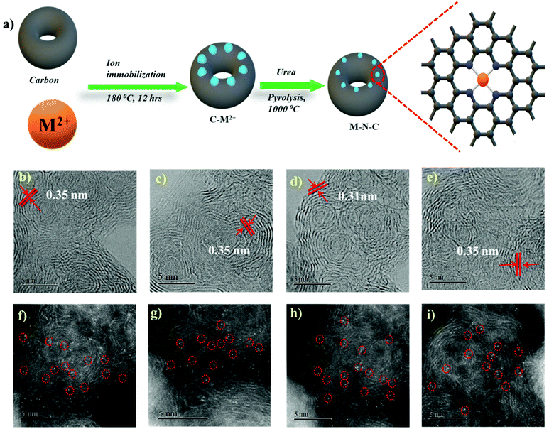
In order to form a similar coordination environment and active sites for CO2 to CO conversion, commercially available carbon black with an activated surface to trap metal atoms was used. Due to the presence of defects and oxygen-containing functional groups on the surface, activated carbon black possesses a high adsorption capacity to metal cations in aqueous solution. An illustration of the synthetic process for the catalyst is shown in Fig. 1a. The surface morphology of the catalysts was examined by SEM and TEM. SEM images show the morphology of the immobilized catalyst as a porous nature with a ball-like structure (Fig. S1†). High-resolution TEM (HRTEM) combined with XRD diffraction analysis confirmed the absence of aggregation of metals to either nanoparticles or clusters. The amorphous carbon support is predominant in all samples. The absence of peaks associated with oxide-derived particles of the metals further assures the strong confinement of the metal center with the nitrogen of carbon (Fig. S2 and S3†). The presence of all elements and atomic dispersion of the metal were verified by elemental mapping (Fig. S4†). Aberration-corrected bright-field STEM image analysis (Fig. 1b–e) revealed a typical multi-shell structure with interlayer distances of 0.35 nm after annealing on defective graphene layers of carbon. This may act as a coordination matrix for metal ion immobilization. Further investigation of the atomic distribution of the metals by aberration-corrected HAADF-STEM image analysis in the sub-angstrom size (Fig. 1f–i) confirmed the good dispersion of isolated metal atoms on carbon support, all the bright circled dots represent the individual metal atoms on the carbon matrix, which further justifies the strong anchoring of the metal atoms on carbon and assures the absence of nanoparticles or clusters on the carbon support. All these together provide evidence for the strong confinement of metals with the carbon support.The catalyst surface chemical composition and state were investigated by X-ray photoelectron spectroscopy (XPS) (Fig. 2). High-resolution N 1s spectra for Co, Ni, Fe, and Cu–N–C show that the N 1s spectrum was deconvoluted into pyridinic N (∼398.5 eV), Nx–M (∼399.4 eV), pyrrolic N (∼400.3 eV), quaternary (∼401.2 eV), and N–Ox (∼402.9 eV) species19,20,42,46 It was noted that the atomic concentration in all four catalysts is dominated by pyrrolic nitrogen (Table S1 in the ESI†). The oxidation states of the respective metals were further analyzed by a 2p photoelectron signal (Fig. S8†). Two peaks associated with metal 2p1/2 and 2p3/2 at their respective binding energies for each metal with their respective satellite peaks are shown. Metal 2p3/2 shake-up provides an insight into the chemical state of these metals, which is consistent with M2+ species except for Fe–N–C, which shows that the majority of Fe2+ were oxidized to Fe3+.
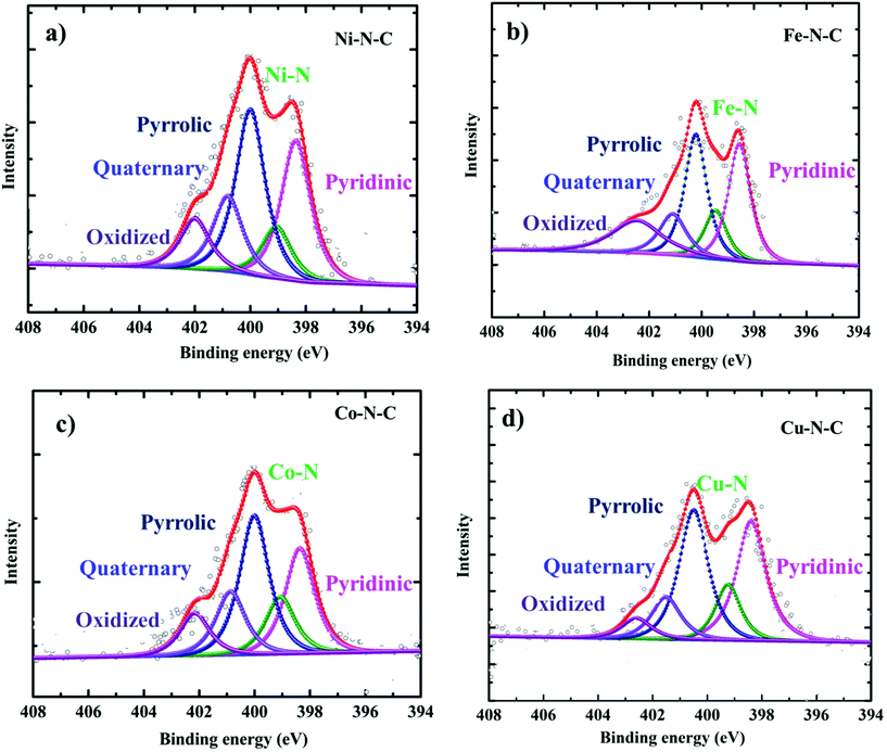 | ||
| Fig. 2 High-resolution XPS characterization. N 1s XPS core level region of (a) Ni–N–C, (b) Fe–N–C, (c) Co–N–C and (d) Cu–N–C catalysts. | ||
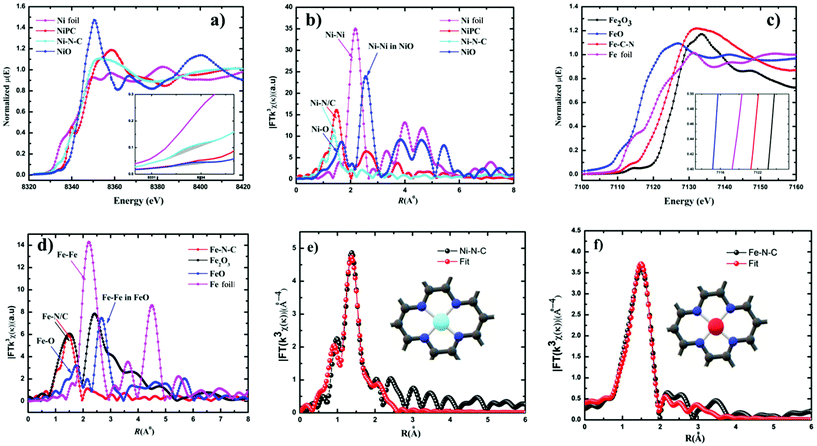
Furthermore, additional detailed structural information about the valence state and local coordination of the metal centers was obtained from X-ray absorption near-edge spectroscopy (XANES) and extended X-ray absorption fine structure (EXAFS) spectroscopy. The Fourier transform (FT) k3-weighted χ(k) function of the EXAFS spectra for Ni–N–C and Fe–N–C exhibited dominant Ni–N and Fe–N coordination with a peak at 1.42 Å and 1.46 Å, respectively (Fig. 3b and d). No peaks corresponding to Ni–Ni and Fe–Fe interactions were observed in either Ni–C–N or Fe–N–C catalysts, confirming that the Ni and Fe species were dispersed as single atoms. The X-ray absorption near-edge structure (XANES) spectrum of Ni–C–N (Fig. 3a) showed that the intensity of the line is located between those for the Ni foil and nickel phthalocyanine (NiPc), suggesting that Ni in our catalyst is an intermediate valence state between Ni0 and Ni2+, while the binding and edge energies of Fe–N–C in XANES (Fig. 3c) resemble Fe2O3, indicating that the Fe ions in the as-synthesized Fe–N–C were in the +3 oxidation state. This further justifies our XPS results, which are also in agreement with previous reports.32,47–49 From the inset (Fig. 3a), the pre-edge of the XANES spectra, the peak at 8.334 eV is assigned to the transition (1s → 3d),48 which signals 3d and 4p orbital hybridizations of the Ni central atoms (Fig. S10†).
Furthermore, the Fourier-transformed EXAFS spectra of both Cu–N–C and Co–N–C showed a main peak at ∼1.5 Å, which could be assigned to the Cu–N and Co–N bonds. Notably, the peak related to Cu–Cu and Co–Co bonds at ∼2.2 Å was absent (Fig. S12†), in both Cu and Co–N–C catalysts. This suggests the presence of individually distributed Cu and Co atoms. Thus, based on the combined HAADF-STEM and EXAFS results, both Cu and Co species were atomically dispersed on the carbon support. The threshold energy of the Cu K-edge XANES spectrum of Cu–N–C showed similar features to that of CuII phthalocyanine (Fig. S12†). This further supports a predominant +II oxidation state of the Cu centers. Co K-edges show that Co–N–C has an intermediate oxidation state between Co and Co(II) (Fig. S12†).
The least-squares EXAFS curve fitting for the first coordination shell without a background correction for both Ni–N–C and Fe–N–C was performed (Fig. 3e and f); the results indicated that both Ni and Fe centers adopt a planar structure with average coordination numbers of Ni–N and Fe–N paths with 3.4 and 3.6, respectively. Furthermore, no metal–metal bond was detected in both catalysts. Both fitting spectra of Ni–N–C and Fe–N–C prove the atomic dispersion of Ni and Fe sites in Ni2+–N–C and Fe3+–N–C, respectively. Furthermore, the fitted results showed both Ni and Fe are coordinated to four N atoms at distances of ∼1.85 Å and ∼1.97 Å, respectively (Table S4†).
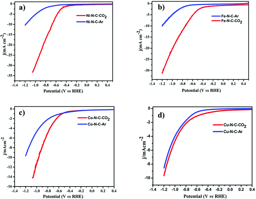
To evaluate the catalytic activity and selectivity for CO2 conversion, linear scanning voltammetry (LSV) values were obtained at a cathodic sweeping rate of 5 mV s−1 in both Ar-saturated and CO2-saturated 0.1 M KHCO3 electrolytes (Fig. 4). Except Co–N–C which showed an onset potential with a significant current increase in N2-saturated 0.1 M KHCO3, which originated from the hydrogen evolution reaction, other catalysts exhibited a higher current density over the entire potential range in the CO2-saturated electrolyte because of the activation of CO2. Reductive current increases as the potential sweeps to a more negative value than −0.3 V vs. reversible hydrogen electrode (RHE) for Fe–N–C reaching a jCO up to 2.7 mA cm−2 at −0.5 V vs. RHE equal to an overpotential of 390 mV, while for Ni–N–C the cathodic current density reaches up to 17.6 mA cm−2 at −0.8 V vs. RHE. Compared to Co–N–C and Cu–N–C, the current density obtained using Ni is far superior. The CO2RR catalytic activity of the M–N–C catalyst, prepared by drop-casting onto 1 cm × 1 cm carbon paper, was evaluated in a standard three-electrode H-cell configuration in CO2-saturated 0.1 M KHCO3 as the electrolyte by gas chromatographic analysis for the gas products and by 1H-NMR analysis for the liquid products. H2 and CO are the major gas products in 2-electron coupled proton/electron transfer reactions according to:
| 2H+(sol) + 2e− + CO2(sol) → H2O(l) + CO(g), | (1) |
| 2H+(sol) + 2e− → H2(g). | (2) |
All the catalytic tests were conducted under a controlled potential for 1 h to understand the fundamental mechanistic reactions of CO2 electroreduction on single-site motifs. Hence, we focus on the trends in the reactivity of different M–N–C catalysts at different potentials. The CO2 electroreduction exhibits strong dependence on the nature of transition metals not only in syngas production but also on overpotentials at which maximum CO efficiencies were observed. During electrolysis, Ni–N–C showed a maximum faradaic efficiency >97% at −0.8 V vs. RHE, while Fe–N–C showed a maximum faradaic efficiency of 86.8% at a lower potential which is −0.5 V vs. RHE (Fig. 5). The partial current and faradaic efficiency showed by Ni–N–C are comparable to those of monodisperse Au nanoparticles and Au nanowires in previous reports.50,51 Thus, Fe–N–C selectively reduces CO2 at lower overpotentials, while Ni–N–C reduces CO2 at higher overpotentials. Cu–N–C is considered as an efficient H2 producer as it showed a H2 FE over 75% during the entire potential range. This makes Cu–N–C a catalyst with poor selectivity toward CO2RR (Fig. 5b). Furthermore, due to the competitive HER at higher overpotentials, the FEs drop gradually in all catalysts.
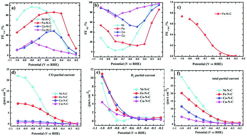 | ||
| Fig. 5 Electrocatalytic CO2RR performance of M–N–C in the H-cell. (a–c) FEs of CO, H2 and CH4 and (d–f) the corresponding steady-state current densities of M–N–C in CO2-saturated 0.1 M KHCO3. | ||
We also noted that the Fe–N–C catalyst has the ability to catalyze the protonation of CO to methane (CH4) like the copper-based catalyst as a small fraction of methane was detected at a potential more negative than −0.3 V vs. RHE (Fig. 5c). A series of control samples with bare carbon (C) and N–C were analyzed to fully understand the catalytic mechanism and path of the CO2RR. M–N–C shows a much larger current density than that on C and N–C (Fig. S14†). Based on this fact, it can be seen that the large response of M–N–C to CO2RR could be mainly attributed to the central metal atoms. To further elucidate the outstanding performance, we carried out electrochemical surface area (ECSA) measurements (Fig. S15 and S16†). The double layer capacitance as a reference of ECSA showed that Ni–N–C possess five times higher ECSA than Cu–N–C, while that of Fe–N–C is three times higher than Cu–N–C. Fe–N–C catalyst showed an ECSA which is six times higher than that of Co–N–C. Thus, the high double layer capacitance of Ni and Fe–N–C was attributed to the higher porosity of these two series of catalysts.
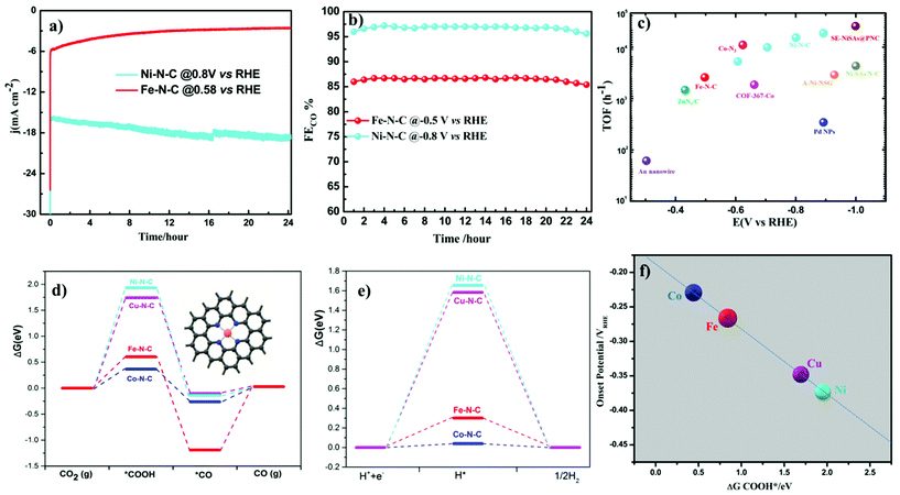
Turnover frequencies (TOFs) for CO production from CO2RR at respective potentials where maximum faradaic efficiency was exhibited based on the partial CO current densities were calculated to confirm the high activity of this family of catalysts. A high TOF of 5.74 s−1 was achieved for the Ni–N–C-based catalyst at −0.8 V vs. RHE which is higher than that of some previously reported state-of-the-art heterogeneous electrocatalysts for CO2 reduction to CO (Fig. 6c and Table S3†). We further analyze the stability of Ni- and Fe-based catalysts at −0.8 V and −0.5 V vs. RHE potentials, respectively. 24 h electrolysis tests were carried out. Partial CO current and CO efficiency versus time were plotted (Fig. 6a and b). We noted a minor drop of CO partial current, while CO FE was held above 95% for Ni–N–C and maximum CO faradaic efficiency was maintained above 80% for the Fe–N–C catalysts. To understand the observed durability of the catalysts, we obtained the XPS spectra and HRTEM image for Fe–N–C and Ni–N–C after CO2RR for 12 h and 24 h, at −0.5 V and −0.8 V vs. RHE, respectively (Fig. S17 and Table S2†). The content of M–Nx shows negligible variation, which is consistent with the observed stable FECO during the prolonged stability test (Fig. 6a and b). HRTEM further shows the absence of nanoparticles or clusters on carbon after the 24 h reactions. All these results indicate that the observed remarkable durability of Fe–N–C and Ni–N–C for CO2RR (Fig. 6a and b) could be due to the remarkable durability of the active component of M–Nx on the catalyst.
Density Functional Theory (DFT) calculations were performed to understand more about the atomistic insight into the origin of improved performance and activity–selectivity trends of M–N–C catalysts. Based on the Ni–N and Fe–N EXAFS curve fitting (Table S4†), Ni and Fe single atoms coordinated by three and four nitrogen atom species embedded in carbon were both considered in DFT calculations. From the DFT calculations (Fig. 6 and Fig. S20†), we noted that the catalytic activity shows different rates of dependence on the nature of metal center and applied potentials. Our experimental results also pinpoint the order in the change of catalytic activity at different potentials indicating that the activity of CO2RR strongly depends up on the nature of the metal center. During CO2RR, the main rate-determining step is the formation of COOH*, which determines the required overpotential. As shown in the Gibbs free energy diagrams in Fig. 6d, the binding of COOH is strong on Fe–N–C and Co–N–C, indicating that only a low overpotential is needed for the electroreduction of CO2 to CO, while the binding of COOH on both Ni–N–C and Cu–N–C systems is very weak, indicating that these two systems need a relatively large overpotential for CO2RR. These results further proved by our experimental findings show that at lower overpotentials (near the onset) Fe–N–C and Co–N–C start to reduce CO2, while Ni–N–C and Cu–N–C need more potential, as evidenced by the relationship between ΔGCOOHvs. onset potentials (Fig. 6e). Desorption of *CO is the other main rate-determining step for CO2RR. In order to achieve high rates of CO2 reduction, desorption of *CO should be fast, i.e. the CO binding should be weak. At 0 eV potential (Fig. 6d and Fig. S20†), CO cannot adsorb on the Ni–N–C and Cu–N–C catalysts. The binding of CO on Co–N–C is very weak (ΔG is −0.263 and 0.165 eV for 4-coordinated and 3-coordinated Co–N–C, respectively), while the binding of CO on 4-coordinated Fe–N–C is much stronger with a ΔG of −1.193 eV. The strong binding makes the desorption of CO difficult on 4-coordinated Fe–N–C and has been fully supported by our experimental results. Among all the catalysts, Fe–N–C is the only one to produce CH4, which requires CO to bind strong enough and long enough on the catalyst to undergo dissociation and hydrogenation steps to give CH4. For the other catalysts, no CH4 is found because the desorption of CO is fast and it prevents CO from further transformation. To further understand what happens at the intermediate potentials we calculated the free energy at −0.5 V vs. RHE, and it was observed that at a potential around −0.5 V vs. RHE, Fe–N–C and Co–N–C reach their maximum CO production (Fig. S19†). The overall CO2 reduction reaction was limited by a non-faradaic chemical reaction, i.e. CO* → CO(g) at this potential (−0.5 V vs. RHE), while Ni–N–C and Cu–N–C started to generate CO. The limiting step is the formation of *COOH, indicating that an increase of applied potentials can increase the CO yield of Ni–N–C and Cu–N–C. These results exactly explain why the CO yield increases in the range of −0.5 to −0.8 vs. RHE for Ni–N–C and Cu–N–C. At very high over potentials >0.9 vs. RHE, with a further increase of the applied potentials, the CO yield and the jCO decrease because the competition process of HER becomes more relevant (Fig. 5a).
Cu–N–C was found to be the most efficient catalyst for H2 formation over the entire potential range and we found experimentally that the reactivity trend of Cu–N–C does not follow that of Ni. This is due to the thermodynamic instability of Cu moieties under strongly reducing potentials <−0.7 V vs. RHE. Thus, the Cu–N–C atoms spontaneously reduce to metallic Cu nanoparticles.52 As a result, Cu–N–C showed lower CO efficiency, lower jCO and high faradaic efficiency for H2. In contrast, Ni centers exhibited very weak binding energy toward *H making the HER thermodynamically unfavorable and resulting in the observed low production of H2 and high CO selectivity. The Ni–N–C catalyst continues to increase its CO production rate at a very high faradaic CO efficiency, significantly outperforming all other single-site catalysts. The mechanistic DFT calculations shown in Fig. 6 concisely explain all the experimental findings evidencing that Fe and Co catalysts start to strongly catalyze the HER as illustrated by their low ΔG of H*. To elucidate the mechanism, the adsorption of CO2 molecules initially occurs with proton-coupled electron transfer reduction to form adsorbed *COOH (CO2 + * + H+ + e− → *COOH). Then, the formed M–N–C–COOH intermediate undergoes further proton–electron transfer reduction to form a *CO intermediate and release the H2O molecule (*COOH + H+ + e− → *CO + H2O). Finally CO is generated from the weak dissociation of *CO intermediates (*CO → CO + *). Thus, the DFT predictions of the CO2RR pathway at 0 V vs. RHE complete the mechanistic picture proposed (Fig. 7).
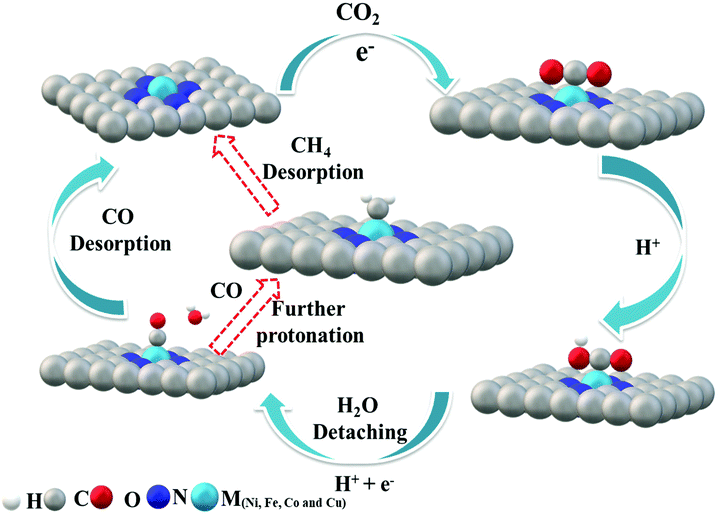 | ||
| Fig. 7 Proposed reaction paths for CO2 electroreduction by M–N–C. Fe–N–C follows the red arrow to further undergo protonation to give methane (CH4). | ||
3. Conclusion
In this article, we have demonstrated a simple, scalable and low-cost immobilization of well-defined SACs for electrocatalytic CO2 reduction to CO. An immobilized Ni single metal reduces CO2 at higher overpotentials with high selectivity and TOF compared to other catalysts, while Fe–N–C works better at lower overpotentials. We pointed out the importance of metal centers during electroreduction. DFT-based computational analysis revealed the mechanistic origin of the reactivity–selectivity trends between Ni–N–C, Fe–N–C, Co–N–C and Cu–N–C catalyst surfaces. The selective reduction of CO2 strongly depends on the nature of the metal center as different metal centers selectively reduce CO2 at different potentials. Further, we confirmed our experimental results with regard to the ability of the Fe–N–C catalyst to reduce CO2 to a hydrocarbon, methane, through computational simulation in which *CO strongly adsorbed and bound to the Fe site for further protonation. In general, the family of metal/nitrogen doped carbons also features a large, to-date unexplored set of choices for the central metal ion M, which holds an alternative promise of more efficient catalyst candidates.Conflicts of interest
The authors declare that they have no conflict of interest.Acknowledgements
The authors acknowledge financial support from the Strategic Priority Research Program of the Chinese Academy of Sciences (XDB36000000, Z. Y. T.), the National Key Basic Research Program of China (2016YFA0200700, Z. Y. T.), the National Natural Science Foundation of China (51772957, Y. G.; 21890381 and 21721002, Z. Y. T.), the Frontier Science Key Project of the Chinese Academy of Sciences (QYZDJ-SSW-SLH038, Z. Y. T.), and the K. C. Wong Education Foundation (Z. Y. T.).References
- L. Wang, W. Chen, D. Zhang, Y. Du, R. Amal, S. Qiao, J. Wu and Z. Yin, Chem. Soc. Rev., 2019, 48, 5310–5349 RSC.
- A. Vasileff, Y. Zheng and S. Z. Qiao, Adv. Energy Mater., 2017, 7, 1700759 CrossRef.
- L. Hou, J. Yan, L. Takele, Y. Wang, X. Yan and Y. Gao, Inorg. Chem. Front., 2019, 6, 3363–3380 RSC.
- Z. W. Seh, J. Kibsgaard, C. F. Dickens, I. B. Chorkendorff, J. K. Nørskov and T. F. Jaramillo, Science, 2017, 355, eaad4998 CrossRef PubMed.
- X. Jiang, H. Li, J. Xiao, D. Gao, R. Si, F. Yang, Y. Li, G. Wang and X. Bao, Nano Energy, 2018, 52, 345–350 CrossRef CAS.
- M. G. Kibria, J. P. Edwards, C. M. Gabardo, C. T. Dinh, A. Seifitokaldani, D. Sinton and E. H. Sargent, Adv. Mater., 2019, 31, 1807166 CrossRef PubMed.
- Y. Cheng, S. Yang, S. P. Jiang and S. Wang, Small Methods, 2019, 3, 1800440 CrossRef.
- S. Back, M. S. Yeom and Y. Jung, ACS Catal., 2015, 5, 5089–5096 CrossRef CAS.
- M. Ma, K. Liu, J. Shen, R. Kas and W. A. Smith, ACS Energy Lett., 2018, 3, 1301–1306 CrossRef CAS PubMed.
- C. Kim, H. S. Jeon, T. Eom, M. S. Jee, H. Kim, C. M. Friend, B. K. Min and Y. J. Hwang, J. Am. Chem. Soc., 2015, 137, 13844–13850 CrossRef CAS PubMed.
- W. Luc, C. Collins, S. Wang, H. Xin, K. He, Y. Kang and F. Jiao, J. Am. Chem. Soc., 2017, 139, 1885–1893 CrossRef CAS PubMed.
- D. Kim, J. Resasco, Y. Yu, A. M. Asiri and P. Yang, Nat. Commun., 2014, 5, 1–8 Search PubMed.
- Q. Lu, J. Rosen, Y. Zhou, G. S. Hutchings, Y. C. Kimmel, J. G. Chen and F. Jiao, Nat. Commun., 2014, 5, 1–6 Search PubMed.
- Y. Hori, H. Wakebe, T. Tsukamoto and O. Koga, Electrochim. Acta, 1994, 39, 1833–1839 CrossRef CAS.
- Z.-L. Wang, C. Li and Y. Yamauchi, Nano Today, 2016, 11, 373–391 CrossRef CAS.
- H. Mitta, P. Balla, N. Nekkala, K. M. Bhaskara, R. Boddula, V. Kannekanti and R. R. Kokkerapati, Recent Progress of Carbon Dioxide Conversion into Renewable Fuels and Chemicals Using Nanomaterials, Springer, 2019, pp. 271–293 Search PubMed.
- A. S. Varela, N. Ranjbar Sahraie, J. Steinberg, W. Ju, H. S. Oh and P. Strasser, Angew. Chem., Int. Ed., 2015, 54, 10758–10762 CrossRef CAS PubMed.
- P. P. Sharma, J. Wu, R. M. Yadav, M. Liu, C. J. Wright, C. S. Tiwary, B. I. Yakobson, J. Lou, P. M. Ajayan and X. D. Zhou, Angew. Chem., Int. Ed., 2015, 54, 13701–13705 CrossRef CAS PubMed.
- K. Jiang, S. Siahrostami, T. Zheng, Y. Hu, S. Hwang, E. Stavitski, Y. Peng, J. Dynes, M. Gangisetty and D. Su, Energy Environ. Sci., 2018, 11, 893–903 RSC.
- T. Möller, W. Ju, A. Bagger, X. Wang, F. Luo, T. N. Thanh, A. S. Varela, J. Rossmeisl and P. Strasser, Energy Environ. Sci., 2019, 12, 640–647 RSC.
- K. Niu, Y. Xu, H. Wang, R. Ye, H. L. Xin, F. Lin, C. Tian, Y. Lum, K. C. Bustillo and M. M. Doeff, Sci. Adv., 2017, 3, e1700921 CrossRef PubMed.
- C. Zhao, X. Dai, T. Yao, W. Chen, X. Wang, J. Wang, J. Yang, S. Wei, Y. Wu and Y. Li, J. Am. Chem. Soc., 2017, 139, 8078–8081 CrossRef CAS PubMed.
- X. Li, W. Bi, M. Chen, Y. Sun, H. Ju, W. Yan, J. Zhu, X. Wu, W. Chu and C. Wu, J. Am. Chem. Soc., 2017, 139, 14889–14892 CrossRef CAS PubMed.
- P. Su, K. Iwase, S. Nakanishi, K. Hashimoto and K. Kamiya, Small, 2016, 12, 6083–6089 CrossRef CAS PubMed.
- F. Yang, P. Song, X. Liu, B. Mei, W. Xing, Z. Jiang, L. Gu and W. Xu, Angew. Chem., Int. Ed., 2018, 57, 12303–12307 CrossRef CAS PubMed.
- C. Zhu, Q. Shi, B. Z. Xu, S. Fu, G. Wan, C. Yang, S. Yao, J. Song, H. Zhou and D. Du, Adv. Energy Mater., 2018, 8, 1801956 CrossRef.
- B. Zhang, J. Zhang, J. Shi, D. Tan, L. Liu, F. Zhang, C. Lu, Z. Su, X. Tan and X. Cheng, Nat. Commun., 2019, 10, 1–8 CrossRef PubMed.
- C. Zhang, S. Yang, J. Wu, M. Liu, S. Yazdi, M. Ren, J. Sha, J. Zhong, K. Nie and A. S. Jalilov, Adv. Energy Mater., 2018, 8, 1703487 CrossRef.
- T. Asset, S. T. Garcia, S. Herrera, N. Andersen, Y. Chen, E. J. Peterson, I. Matanovic, K. Artyushkova, J. Lee and S. D. Minteer, ACS Catal., 2019, 9, 7668–7678 CrossRef CAS.
- Q. Fan, P. Hou, C. Choi, T. S. Wu, S. Hong, F. Li, Y. L. Soo, P. Kang, Y. Jung and Z. Sun, Adv. Energy Mater., 2020, 10, 1903068 CrossRef CAS.
- P. Lu, Y. Yang, J. Yao, M. Wang, S. Dipazir, M. Yuan, J. Zhang, X. Wang, Z. Xie and G. Zhang, Appl. Catal., B, 2019, 241, 113–119 CrossRef CAS.
- J. Gu, C.-S. Hsu, L. Bai, H. M. Chen and X. Hu, Science, 2019, 364, 1091–1094 CrossRef CAS PubMed.
- F. Pan, H. Zhang, K. Liu, D. Cullen, K. More, M. Wang, Z. Feng, G. Wang, G. Wu and Y. Li, ACS Catal., 2018, 8, 3116–3122 CrossRef CAS.
- H. Zhang, J. Li, S. Xi, Y. Du, X. Hai, J. Wang, H. Xu, G. Wu, J. Zhang and J. Lu, Angew. Chem., 2019, 131, 15013–15018 CrossRef.
- Y. Pan, R. Lin, Y. Chen, S. Liu, W. Zhu, X. Cao, W. Chen, K. Wu, W.-C. Cheong and Y. Wang, J. Am. Chem. Soc., 2018, 140, 4218–4221 CrossRef CAS PubMed.
- X. Wang, Z. Chen, X. Zhao, T. Yao, W. Chen, R. You, C. Zhao, G. Wu, J. Wang and W. Huang, Angew. Chem., Int. Ed., 2018, 57, 1944–1948 CrossRef CAS PubMed.
- L. Shang, H. Yu, X. Huang, T. Bian, R. Shi, Y. Zhao, G. I. N. Waterhouse, L. Z. Wu, C. H. Tung and T. Zhang, Adv. Mater., 2016, 28, 1668–1674 CrossRef CAS PubMed.
- Y. Chen, S. Ji, Y. Wang, J. Dong, W. Chen, Z. Li, R. Shen, L. Zheng, Z. Zhuang and D. Wang, Angew. Chem., Int. Ed., 2017, 56, 6937–6941 CrossRef CAS PubMed.
- C. Costentin, S. Drouet, M. Robert and J.-M. Savéant, Science, 2012, 338, 90–94 CrossRef CAS PubMed.
- N. Kornienko, Y. Zhao, C. S. Kley, C. Zhu, D. Kim, S. Lin, C. J. Chang, O. M. Yaghi and P. Yang, J. Am. Chem. Soc., 2015, 137, 14129–14135 CrossRef CAS PubMed.
- J. Shen, R. Kortlever, R. Kas, Y. Y. Birdja, O. Diaz-Morales, Y. Kwon, I. Ledezma-Yanez, K. J. P. Schouten, G. Mul and M. T. M. Koper, Nat. Commun., 2015, 6, 1–8 Search PubMed.
- T. Zheng, K. Jiang, N. Ta, Y. Hu, J. Zeng, J. Liu and H. Wang, Joule, 2019, 3, 265–278 CrossRef CAS.
- W. Ju, A. Bagger, G.-P. Hao, A. S. Varela, I. Sinev, V. Bon, B. R. Cuenya, S. Kaskel, J. Rossmeisl and P. Strasser, Nat. Commun., 2017, 8, 1–9 CrossRef CAS PubMed.
- V. Tripkovic, M. Vanin, M. Karamad, M. R. E. Björketun, K. W. Jacobsen, K. S. Thygesen and J. Rossmeisl, J. Phys. Chem. C, 2013, 117, 9187–9195 CrossRef CAS.
- A. Bagger, W. Ju, A. S. Varela, P. Strasser and J. Rossmeisl, Catal. Today, 2017, 288, 74–78 CrossRef CAS.
- K. Artyushkova, B. Kiefer, B. Halevi, A. Knop-Gericke, R. Schlogl and P. Atanassov, Chem. Commun., 2013, 49, 2539–2541 RSC.
- T. N. Huan, N. Ranjbar, G. Rousse, M. Sougrati, A. Zitolo, V. Mougel, F. Jaouen and M. Fontecave, ACS Catal., 2017, 7, 1520–1525 CrossRef CAS.
- H. B. Yang, S.-F. Hung, S. Liu, K. Yuan, S. Miao, L. Zhang, X. Huang, H.-Y. Wang, W. Cai and R. Chen, Nat. Energy, 2018, 3, 140–147 CrossRef CAS.
- W. Liu, L. Zhang, X. Liu, X. Liu, X. Yang, S. Miao, W. Wang, A. Wang and T. Zhang, J. Am. Chem. Soc., 2017, 139, 10790–10798 CrossRef CAS PubMed.
- W. Zhu, R. Michalsky, O. N. Metin, H. Lv, S. Guo, C. J. Wright, X. Sun, A. A. Peterson and S. Sun, J. Am. Chem. Soc., 2013, 135, 16833–16836 CrossRef CAS PubMed.
- W. Zhu, Y.-J. Zhang, H. Zhang, H. Lv, Q. Li, R. Michalsky, A. A. Peterson and S. Sun, J. Am. Chem. Soc., 2014, 136, 16132–16135 CrossRef CAS PubMed.
- Y. Hori, A. Murata and R. Takahashi, J. Chem. Soc., Faraday Trans., 1989, 85, 2309–2326 RSC.
Footnotes |
| † Electronic supplementary information (ESI) available. See DOI: 10.1039/d0nr03044a |
| ‡ These authors contributed equally to this work. |
| This journal is © The Royal Society of Chemistry 2020 |

