
 Open Access Article
 This Open Access Article is licensed under a Creative Commons Attribution-Non Commercial 3.0 Unported Licence
Step-induced double-row pattern of interfacial water on rutile TiO2(110) under electrochemical conditions†
Yan
Sun
a,
Cheng-Rong
Wu
a,
Feng
Wang
a,
Rui-Hao
Bi
a,
Yong-Bin
Zhuang
 a,
Shuai
Liu
a,
Ming-Shu
Chen
a,
Kelvin H.-L.
Zhang
*a,
Jia-Wei
Yan
*a,
Bing-Wei
Mao
a,
Zhong-Qun
Tian
ab and
Jun
Cheng
*abc
a,
Shuai
Liu
a,
Ming-Shu
Chen
a,
Kelvin H.-L.
Zhang
*a,
Jia-Wei
Yan
*a,
Bing-Wei
Mao
a,
Zhong-Qun
Tian
ab and
Jun
Cheng
*abc
aState Key Laboratory of Physical Chemistry of Solid Surfaces, iChEM, College of Chemistry and Chemical Engineering, Xiamen University, Xiamen 361005, China. E-mail: kelvinzhang@xmu.edu.cn; jwyan@xmu.edu.cn; chengjun@xmu.edu.cn
bLaboratory of AI for Electrochemistry (AI4EC), IKKEM, Xiamen 361005, China
cInstitute of Artificial Intelligence, Xiamen University, Xiamen 361005, China
First published on 24th May 2024
Abstract
Metal oxides are promising (photo)electrocatalysts for sustainable energy technologies due to their good activity and abundant resources. Their applications such as photocatalytic water splitting predominantly involve aqueous interfaces under electrochemical conditions, but in situ probing oxide–water interfaces is proven to be extremely challenging. Here, we present an electrochemical scanning tunneling microscopy (EC-STM) study on the rutile TiO2(110)–water interface, and by tuning surface redox chemistry with careful potential control we are able to obtain high quality images of interfacial structures with atomic details. It is interesting to find that the interfacial water exhibits an unexpected double-row pattern that has never been observed. This finding is confirmed by performing a large scale simulation of a stepped interface model enabled by machine learning accelerated molecular dynamics (MLMD) with ab initio accuracy. Furthermore, we show that this pattern is induced by the steps present on the surface, which can propagate across the terraces through interfacial hydrogen bonds. Our work demonstrates that by combining EC-STM and MLMD we can obtain new atomic details of interfacial structures that are valuable to understand the activity of oxides under realistic conditions.
Earth-abundant metal oxides are among the most promising (photo)electrocatalysts in a wide range of environmental and energy applications owing to their excellent activity, low costs and high stability under reactive conditions.1–4 Since the vast majority of these reactions operate in solution, understanding oxide–water interfaces at the atomic level is a prerequisite for elucidating fundamental mechanisms and rationally optimising catalytic performances.5 Thus, tremendous efforts, both experimentally and computationally, have been devoted to revealing the microscopic details of the interfaces. For example, X-ray absorption,6 Raman7 and sum frequency generation spectroscopies8,9 have been developed to in situ probe the interfaces, and can provide valuable interfacial information, often helped by density functional theory (DFT) calculation for interpreting spectra.10,11
Among those techniques, scanning tunneling microscopy (STM) has a prominent position and can directly offer images of atomic structures of the surfaces. The combination of STM and DFT has been the workhorse for development of oxide surface science in ultrahigh vacuum (UHV), most notably on the all-important model system TiO2.12–17 Somewhat in parallel, electrochemical STM (EC-STM) has been developed by the electrochemistry community for probing interfacial structures on metal electrodes.18–22 However, it is very challenging to operate EC-STM on oxides, due to various difficulties such as low electrical conductivity, preparation of clean, atomically flat surfaces and potential control of imaging conditions. As a result, EC-STM studies on oxides are rare, and limited information can be extracted.23–25
Here, we present a combined EC-STM and machine learning accelerated molecular dynamics (MLMD) study on the single crystal rutile TiO2(110) surface under electrochemical conditions (Fig. 1). Fine-tuning the electrode potential condition of the oxide substrate enables us to play with the surface redox chemistry, leading to high quality STM images with atomic details of interfacial structures. We discover that the TiO2(110) surface under electrochemical conditions exhibits an unexpected double-row pattern, which has not been observed under UHV and low vapor pressure conditions. We then utilize MLMD that affords long time scale simulations26–28 of large interface models with ab initio accuracy (Fig. 1(c)), to reveal that this special pattern can be assigned to the adsorbed water at the five-coordinated Ti (Ti5c) trough that shows a universal shift away from the centre to the row of bridging oxygen. What is surprising is that this asymmetric structure results from the biased water configurations at the [1![[1 with combining macron]](https://www.rsc.org/images/entities/char_0031_0304.gif) 1] steps present at the edges of terraces of width of hundreds of nanometers on the single crystal TiO2(110) surface. Our work demonstrates that distinct from that in a vacuum, the interfacial water structure on TiO2(110) is subjected to a long range effect due to the symmetry breaking boundary of step edges, which are expected to be widely applicable to nanostructures with finite facets in realistic environments.
1] steps present at the edges of terraces of width of hundreds of nanometers on the single crystal TiO2(110) surface. Our work demonstrates that distinct from that in a vacuum, the interfacial water structure on TiO2(110) is subjected to a long range effect due to the symmetry breaking boundary of step edges, which are expected to be widely applicable to nanostructures with finite facets in realistic environments.
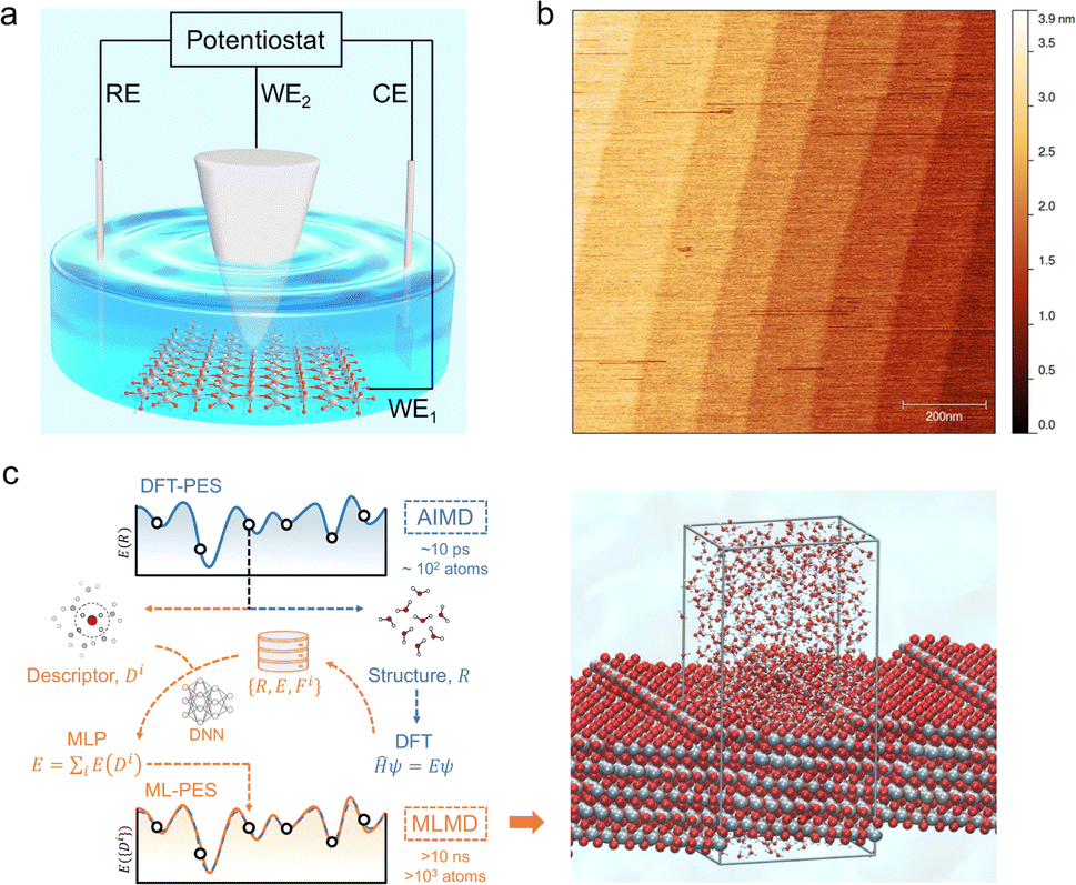 | ||
| Fig. 1 (a) Schematic illustration of the EC-STM cell. The four-electrode setup consists of a working oxide substrate (WE1), STM tip (WE2), counter electrode (CE) and quasi-reference electrode (RE). (b) AFM image of the rutile TiO2 (110) surface with a size of 1 × 1 μm2. The measured step height is 3.2 ± 0.5 Å. (c) Schematic illustration of the MLMD simulation of the rutile TiO2(110)–water interface with a [11] step, where Ti, O and H atoms are coloured in grey, red and white, respectively. The high computational costs of DFT calculation limit ab initio molecular dynamics (AIMD) to simulate models of ∼102 atoms at a time scale of ∼10 ps. When trained with a deep neural network (DNN) on a relative small set of data generated from DFT, energies and forces can be predicted by machine learning potentials (MLP) from structural descriptors with ab initio accuracy. The difference between the machine learned potential energy surface (ML-PES) and DFT-PES is negligible. Due to the high efficiency, MLMD enables much longer simulations of larger models at lower costs. | ||
The rutile TiO2(110) surface was prepared by HF etching, followed by annealing at 950 °C in oxygen flow. This treatment29 can give a very high-quality, atomically flat surface with a terrace width of ∼200 nm and an atomic step height of 3.2 ± 0.5 Å, as shown by the atomic force microscopy (AFM) image (see Fig. 1(b) and also Fig. S1 in the ESI†). We first investigated the electrochemistry of the rutile TiO2(110) in 0.1 M HClO4 using cyclic voltammetry (CV). As shown in Fig. 2(a), a pair of redox peaks at around −0.25 V vs. Saturated Calomel Electrode (SCE) are clearly observed, which can be assigned to the surface redox process (TiIVO2 + e− ↔ TiIIIO2).30 Note that these peaks are detected at a faster scan rate of 1 V s−1 and disappear at a lower scan rate of 0.02 V s−1 because the peak current is proportional to the scan rate and becomes too small at a low scan rate to be distinguished.31 The EC-STM measurements were carried out in a four-electrode cell setup consisting of a working oxide substrate (WE1), STM tip (WE2), counter electrode (CE) and quasi-reference electrode (RE). Unlike STM operation under UHV conditions, EC-STM images are obtained by controlling the potential of the oxide substrate and STM tip independently (see Fig. 1(a)). Interestingly, we find that high resolution STM images of the TiO2 surface can be obtained when the substrate potential is tuned to −0.38 to −0.18 V vs. SCE, and at the same time the tip potential is maintained in the range of 0.27–1.32 V vs. SCE, as illustrated in Fig. 2(b)–(d).
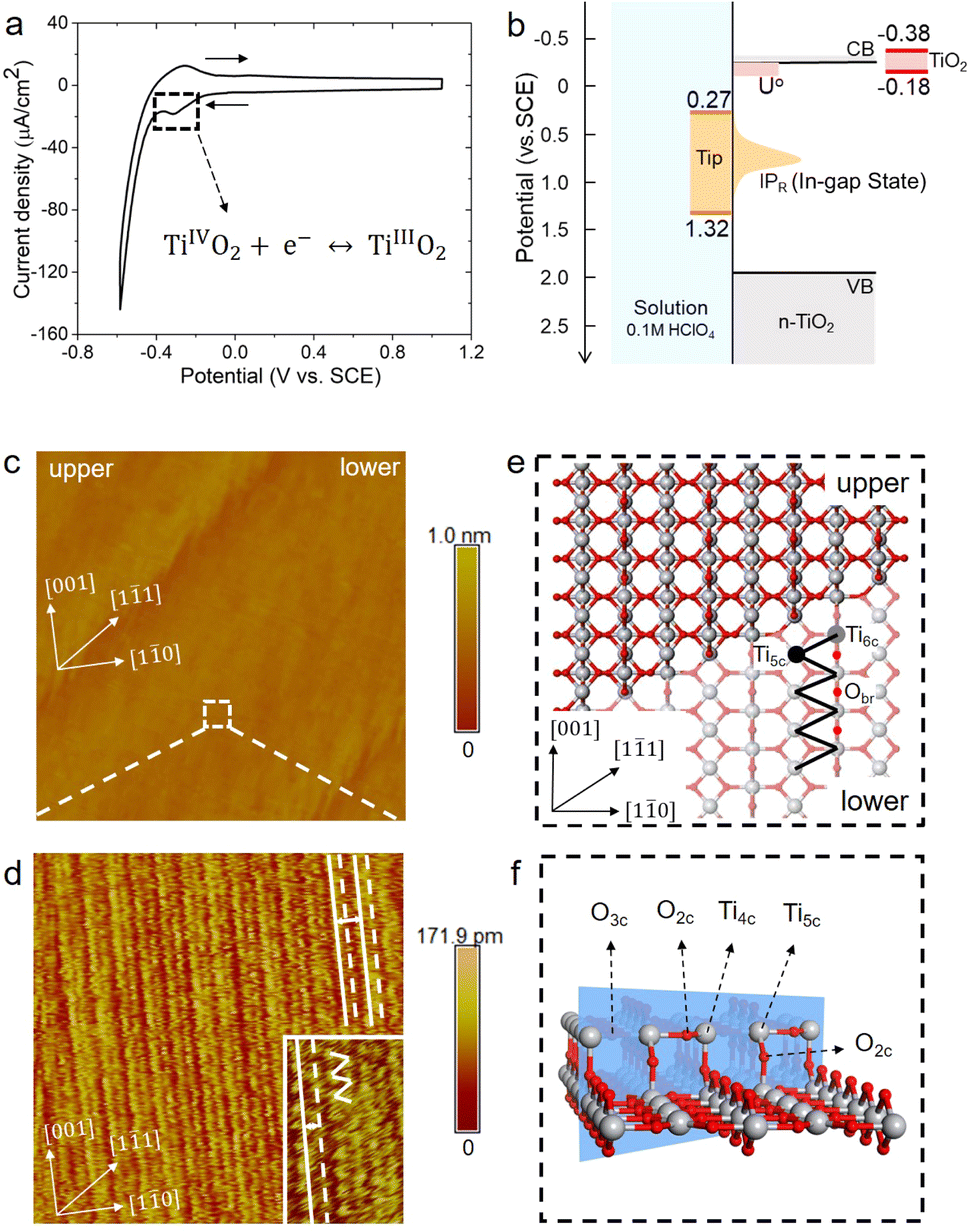 | ||
| Fig. 2 (a) Cyclic voltammogram of the rutile TiO2(110) electrode in 0.1 M HClO4 at a scan rate of 1 V s−1. (b) Level diagram at the TiO2 water interface in the EC-STM configuration. The light red and orange regions indicate the reduction potential of surface TiIV/TiIII states (U°) and the vertical ionization potential of the corresponding reduced TiIII state (IPR), respectively. The red and orange range solid bars show the potential ranges of the oxide sample and the STM tip adjusted to give high quality images. (c) Large area (150 × 150 nm2) of the EC-STM image of the rutile TiO2(110) in 0.1 M HClO4. EC-STM parameters are Esample = −0.38 V vs. SCE, Etip = 1.27 V vs. SCE, and Itunnel = 1 nA, respectively. (d) Magnified area (10 × 10 nm2) with atomic resolution of the white dashed square in (c). The inset shows a further magnified area of 3 × 5 nm2. (e) Top view of the atomistic model of the rutile TiO2(110) surface with a [11] step. (f) Atomistic structure of the [11] step. Ti and O atoms are coloured in grey and red, respectively. | ||
Before interpreting the STM images, it would be informative to first answer two important questions; (i) why do the two potentials have to be tuned to these values? And (ii) why do they have to be set simultaneously? It is worth noting that the tuned substrate potential exactly overlaps with the reduction peak of CV in Fig. 2(a), indicating that the TiO2 surface just undergoes reduction to form surface TiIII. On the other hand, it is well known that on defective TiO2 a band-gap state can be observed in X-ray photoelectron spectroscopy (XPS) around 0.9 eV below the conduction band minimum (CBM), which is associated with an excess electron occupying the Ti 3d state.32,33 By employing an accurate hybrid density functional, Cheng and co-workers34 calculated a number of reduced TiIII states near the TiO2 surface, and found that the redox levels of these states are near or just below the CBM while the corresponding vertical ionization potentials are about 0.6–1.5 eV below the CBM. Putting all these levels together, we draw a level diagram as shown in Fig. 2(b), and note that the band positions are adjusted to the pH = 1 condition according to the Nernstian relation. The two questions above can now be resolved as follows. Scanning the substrate potential to more negative than the reduction peak of the TiO2 surface around −0.25 V vs. SCE, the surface will be reduced to form band-gap states associated with Ti 3d states. These reduced, in-gap states, lying in about 1 eV range centered around 1 eV below the CBM (i.e. 0.3–1.3 V vs. SCE), can then resonate with the STM tip adjusted to the same potential so that high resolution STM images can be collected. It should be noted that if the substrate potential is too negative, i.e. < −0.38 V vs. SCE, the hydrogen evolution current becomes too large to obtain stable STM images (see Fig. S3†).
Fig. 2(d) shows a high resolution STM image of the aqueous rutile TiO2(110), as taken and magnified from the white dashed square on the terrace in Fig. 2(c). Considering the dynamic electrochemical environment at ambient temperature, the image quality is excellent and adequate for analyzing the interfacial structure. Under the imaging conditions mentioned above, the STM image obtained corresponds to the occupied in-gap states, suggesting that the bright rows represent the density of the excess electrons at reduced surface Ti sites along the [001] direction. As shown by the magnified area in the inset of Fig. 2(d), the zig-zag pattern from the underlying terminal and bridge Ti sites in the adjacent rows (Fig. 2(e)) is also visible. Similar STM images were observed on defective TiO2 under UHV conditions.35–37 There is however a noticeable difference in the STM pattern between the two conditions; the bright rows are evenly spaced in UHV, while under electrochemical conditions a doubly alternating pattern of the bright rows can be clearly identified, which was not recognizable in previous STM studies on the aqueous TiO2 surface.24,25 It should be stressed that this double-row pattern has excellent reproducibility, and more high resolution STM images with the same double-row spacing obtained by different tips from different experiments are illustrated in Fig. S4.† The good repeatability of the double-row spacing can effectively eliminate the possibility that the double-row pattern may be caused by the double tip,38 because the spacing of the double row caused by the double tip would change with the spacing of the double tip in different experiments. It is also worth mentioning that this pattern is distinctly different from the double-stranded structure of (1 × 2) on TiO2(110) observed in UHV-STM, which has been ascribed to the Ti2O3 added row.39,40 The distance between two vicinal double-rows, i.e. two solid white lines in Fig. 2(d), is calibrated to be 6.60 ± 0.30 Å, which is further confirmed by the fast Fourier transform (FFT) in Fig. S14.† This value is very close to the lattice constant, 6.50 Å, of the rutile TiO2(110) surface along the [10] direction, and is much less than the spacing of double strands of the Ti2O3 added row (about 13 Å).39,40 Intriguingly, the distance between two adjacent bright rows (i.e. solid and dashed white lines) within a repeating unit is only 3.08 Å, which is considerably shorter than half of the lattice constant of 3.25 Å.
It is unlikely that the alternating double-row pattern reflects the actual distortion of the underlying lattice of TiO2, and thus we tentatively hypothesize that it results from the interfacial water interacting with the oxide surface. However, it is still puzzling why neither has a similar pattern been observed on rutile TiO2(110) in a vacuum or at low water vapor pressures by STM experiments,41–43 nor by ab initio molecular dynamics (AIMD) calculation of the TiO2 water interface.44–46 To resolve this puzzle, we train a machine learning potential (MLP) with an iterative concurrent learning protocol47 for describing the TiO2 water interface with ab initio accuracy, and the training procedure and validation of the MLP can be found in the ESI.† The commonly used model of rutile TiO2(110) was first simulated with MLMD, and owing to the efficiency of MLP, we can readily afford a significantly longer time scale of tens of ns, in contrast to tens of ps for AIMD. The finding is however the same; we do not see systematically biased configurations of surface water adsorbed at the terminal Ti sites. As illustrated in Fig. 3(b), the horizontal distances between the adsorbed water and the bridging O atoms on the left (d(l)) and right (d(r)) are indeed the same, i.e. d(l) = d(r) = 3.25 Å, from the MLMD trajectory.
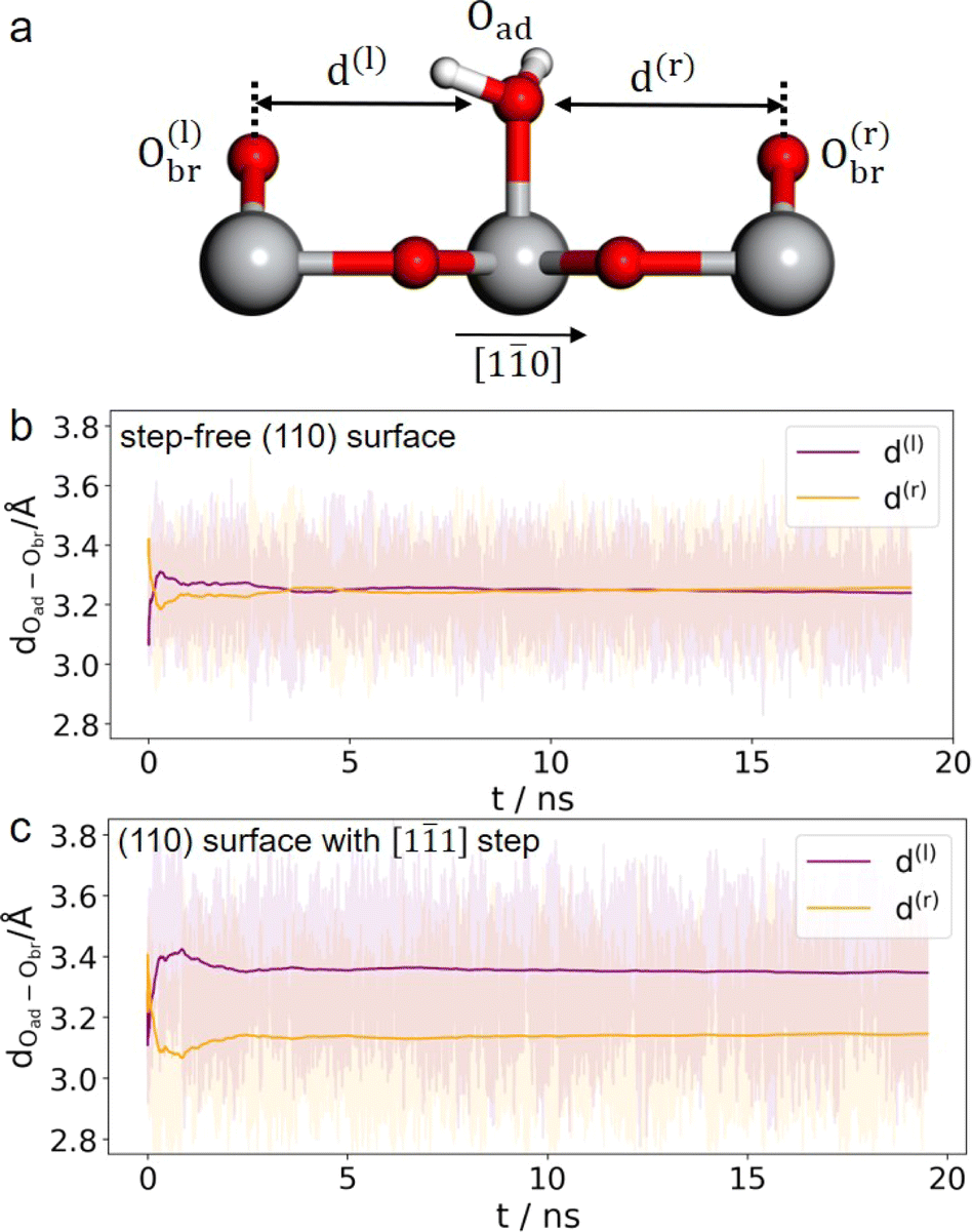 | ||
| Fig. 3 (a) Illustration of the horizontal distances between adsorbed water and the neighboring bridging O atoms. Time evolution of the O–O distances in the step-free rutile TiO2(110) model (b) and that with a [11] step (c) from 20 ns MLMD trajectories. Ti, O and H atoms are coloured in grey, red and white, respectively. | ||
Considering that a large single crystal surface often contains some steps separating narrow terraces (see Fig. 1(b)), we speculate that the symmetry breaking steps might play a role in forming the asymmetric double-row pattern. We thus build a large rutile TiO2(110) surface model with an atomic [11] step separating terraces with 8 terminal Ti sites in a row (see Fig. 1(c) and 2(e), (f)) according to previous studies.38,48 By comparing atomic resolved STM images between 0.1 mol L−1 (Fig. 2(d)) and 0.01 mol L−1 HClO4 (Fig. S17†), we found that the concentration of protons and ClO−4 did not affect the double-row pattern observed. Therefore, the electrolyte used in the MLMD simulation contains only water molecules. Including water molecules, the interface model with a step consists of ∼2000 atoms, about 10 times larger than the commonly used step-free model affordable to AIMD calculation. Somewhat unexpectedly, shortly after starting the MLMD run of the step model with unbiased configurations of surface water, all the adsorbed water molecules spontaneously shift away from the center to one side, and the horizontal distances to the left bridge oxygen and right become significantly different, d(l) = 3.35 Å and d(r) = 3.14 Å in Fig. 3(c). To further validate the long range effect of the atomic step, we double the terrace width to about 5 nm with 16 terminal Ti sites, and this significantly larger model gives the same asymmetric structure of surface water (see more details in ESI†). To remove the effect of uncertainty in distance calibration in STM, we measure the ratio between the spacing of the two nearest rows in a double-row unit and the lattice of the repeating double-row pattern to be 0.47, which is essentially the same as that from MLMD calculation. This quantitative agreement is remarkable; not only does the MLMD calculation correctly represent the interfacial structure of the stepped surface, but also the combination of experiment and theory strongly supports that the presence of the [11] steps on TiO2(110) causes the universal side shift of surface water.
The question then to be answered is why steps can shift adsorbed water on terraces. Carefully examining the water structure on the stepped surface from the MLMD trajectory, we notice that two terminal water molecules at the two ends of the Ti5c trough may play a key role in shifting the whole row of surface water: one is located at the lower terrace of the step edge (“watA” in Fig. 4(a)) and the other at the upper terrace (“watB” in Fig. 4(b)). Near watA, there is a water adsorbed at the Ti4c site of the step edge (“watC” in Fig. 4(a)) forming strong hydrogen bonds (shorter distances than that in bulk water) with the step O2c and the Obr at the lower terrace, as illustrated in Fig. 4(a). The position of watC casts steric repulsion to watA, “pushing” it from the top site of octahedral coordination to the right along the [10] direction (Fig. 4(c)). Also, watB can form a strong hydrogen bond with the bridge water at the step edge (“watD” in Fig. 4(b)), thus being “pulled” to the right. Thus, the “push and pull” effect of the two edge terminal water triggers the side shift of the whole water row. Furthermore, this effect needs to be long-ranged as only a small fraction of steps are present on the surface. It can be proposed that the hydrogen bond network formed within the terminal water row propagates the shifting effect across the whole terraces. We have performed the machine learning molecular dynamics of TiO2–vacuum interfaces with one layer of water adsorbed on the TiO2 surface. As shown in Fig. S10,† this model also exhibits the same shifting behavior of adsorbed water as in the bulk water model, which means that the long-ranged effect would cross the H-bond network between the ordered adsorbed water on the TiO2 surface. Furthermore, to validate the contribution of the H-bond network, 3 water molecules adsorbed on the initial and terminal Ti5c sites are removed from each trough to break the H-bond network between the water adsorbed at the step edge and terrace. As shown in Fig. S11,† the asymmetric distances of adsorbed water molecules are absent with the broken H-bond network, which can prove that the shift of adsorbed water is induced by step defects and propagates through the H-bond network between adsorbed water. In addition, since this continuous H-bond network is absent under UHV and low water vapor pressure conditions, it can be understood why the step-induced double-row pattern has not been observed in experiments carried out under these ideal conditions.
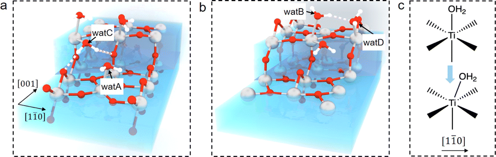 | ||
| Fig. 4 Schematic illustration of water structures at the [11] step on rutile TiO2(110): (a) lower terrace and (b) upper terrace. (c) Illustration of distortion of the octahedral coordination for adsorbed terminal water along [10]. Ti, O and H atoms are coloured in grey, red and white, respectively. | ||
To summarize, by combining EC-STM and MLMD, we show that the interfacial water on rutile TiO2(110) exhibits a doubly alternating pattern due to the presence of a small fraction of steps on the surface. This long range effect results from interfacial hydrogen bonds in aqueous environments, and is missing in previous studies in a vacuum and at low water vapor pressures. Thus, our finding offers a new perspective on the long-ranged H-bond network on the aqueous TiO2 interface, whose tilt characteristics are different from the reported interfacial structure.49 Furthermore, the geometry and strength of the H-bond are essential for proton-coupled electron transfer (PCET) mechanisms.50,51 This strong H-bond network could accelerate charge transfer events for an efficient PCET process,52–54 which may have important implications for understanding catalysis in realistic environments. We also show that by fine-tuning the potential of the sample and STM tip, high resolution images of interfacial structures of oxides can be obtained under electrochemical conditions through surface redox chemistry. Therefore, our work opens up new opportunities for elucidating the atomic structures of oxide–water interfaces with STM and MLMD, and we expect that such a surface redox mediated STM imaging mechanism could be developed for applications to interfaces under realistic conditions in a wider context.
Data availability
Extra data has been included in ESI.†Author contributions
J. C. conceived and designed the project. J. C., J.-W. Y. and K. H.-L. Z. supervised the experiment and calculation. Y. S. performed the EC-STM and AFM experiment, C.-R. W. prepared the single crystal samples, Y. S. and S. L. carried out the CV experiment. R.-H. B., Y.-B. Z. and F. W. performed the calculations. All the authors analysed the results and co-wrote the manuscript.Conflicts of interest
There are no conflicts to declare.Acknowledgements
We acknowledge the funding support by the National Natural Science Foundation of China (grant no. 22225302, 21991151, 21991150, 22021001, 92161113, 21861132015, 91945301, 22072123 and 21872116), the Fundamental Research Funds for the Central Universities (20720220009 and 20720230090), Laboratory of AI for Electrochemistry (AI4EC), and IKKEM (grant no. RD2023100101 and RD2022070501). We thank J. Wang, Y. J. Liu and T. Y. Ding for the help with illustration. Y. S. thanks J. Wang, Y.-J. Liu and T.-Y. Ding for the support on figure preparation.Notes and references
- A. Fujishima and K. Honda, Nature, 1972, 238, 37–38 CrossRef CAS PubMed.
- M. Chen and D. Goodman, Science, 2004, 306, 252–255 CrossRef CAS PubMed.
- J. Suntivich, K. J. May, H. A. Gasteiger, J. B. Goodenough and Y. Shao-Horn, Science, 2011, 334, 1383–1385 CrossRef CAS PubMed.
- J. Schneider, M. Matsuoka, M. Takeuchi, J. Zhang, Y. Horiuchi, M. Anpo and D. W. Bahnemann, Chem. Rev., 2014, 114, 9919–9986 CrossRef CAS PubMed.
- L. R. Baker, U. Diebold, J. Y. Park and A. Selloni, J. Chem. Phys., 2020, 153, 050401 CrossRef CAS PubMed.
- J. J. Velasco Velez, C. H. Wu, T. A. Pascal, L. F. Wan, J. Guo, D. Prendergast and M. Salmeron, Science, 2014, 346, 831–834 CrossRef CAS PubMed.
- Y. Wang, S. Zheng, W. Yang, R. Zhou, Q. He, P. Radjenovic, J. Dong, S. Li, J. Zheng, Z. Yang, G. Attard, F. Pan, Z. Tian and J. Li, Nature, 2021, 600, 81–85 CrossRef CAS PubMed.
- J. A. McGuire and Y. R. Shen, Science, 2006, 313, 1945–1948 CrossRef CAS PubMed.
- D. Yang, Y. Li, X. Liu, Y. Cao, Y. Gao, Y. R. Shen and W.-T. Liu, Proc. Natl. Acad. Sci. U. S. A., 2018, 115, E3888–E3894 CrossRef CAS PubMed.
- M.-P. Gaigeot, M. Sprik and M. Sulpizi, J. Phys.: Condens.Matter, 2012, 24, 124106 CrossRef PubMed.
- C. Li, J. Le, Y. Wang, S. Chen, Z. Yang, J. Li, J. Cheng and Z. Tian, Nat. Mater., 2019, 18, 697–701 CrossRef CAS PubMed.
- R. Schaub, P. Thostrup, N. Lopez, E. Lægsgaard, I. Stensgaard, J. K. Nørskov and F. Besenbacher, Phys. Rev. Lett., 2001, 87, 266104 CrossRef CAS PubMed.
- U. Diebold, Surf. Sci. Rep., 2003, 48, 53–229 CrossRef CAS.
- O. Bikondoa, C. L. Pang, R. Ithnin, C. A. Muryn, H. Onishi and G. Thornton, Nat. Mater., 2006, 5, 189–192 CrossRef CAS.
- M. A. Henderson and I. Lyubinetsky, Chem. Rev., 2013, 113, 4428–4455 CrossRef CAS PubMed.
- H. Hussain, G. Tocci, T. Woolcot, X. Torrelles, C. Pang, D. Humphrey, C. Yim, D. Grinter, G. Cabailh and O. Bikondoa, et al. , Nat. Mater., 2017, 16, 461–466 CrossRef CAS PubMed.
- J. Balajka, M. A. Hines, W. J. DeBenedetti, M. Komora, J. Pavelec, M. Schmid and U. Diebold, Science, 2018, 361, 786–789 CrossRef CAS PubMed.
- N. Tao, Phys. Rev. Lett., 1996, 76, 4066 CrossRef CAS PubMed.
- Y. Fu, Y. Su, D. Wu, J. Yan, Z. Xie and B. Mao, J. Am. Chem. Soc., 2009, 131, 14728–14737 CrossRef CAS PubMed.
- J. H. Pfisterer, Y. Liang, O. Schneider and A. S. Bandarenka, Nature, 2017, 549, 74–77 CrossRef CAS PubMed.
- L. Jacobse, Y. Huang, M. Koper and M. J. Rost, Nat. Mater., 2018, 17, 277–282 CrossRef CAS PubMed.
- X. Wang, Z. Cai, Y. Wang, Y. Feng, H. Yan, D. Wang and L. Wan, Angew. Chem., Int. Ed., 2020, 59, 16098–16103 CrossRef CAS PubMed.
- K. Itaya and E. Tomita, Chem. Lett., 1989, 18, 285–288 CrossRef.
- G. Serrano, B. Bonanni, M. Di Giovannantonio, T. Kosmala, M. Schmid, U. Diebold, A. Di Carlo, J. Cheng, J. VandeVondele and K. Wandelt, et al. , Adv. Mater. Interfaces, 2015, 2, 1500246 CrossRef.
- M. Müllner, J. Balajka, M. Schmid, U. Diebold and S. F. Mertens, J. Phys. Chem. C, 2017, 121, 19743–19750 CrossRef PubMed.
- J. Behler and M. Parrinello, Phys. Rev. Lett., 2007, 98, 146401 CrossRef PubMed.
- A. P. Bartók, M. C. Payne, R. Kondor and G. Csányi, Phys. Rev. Lett., 2010, 104, 136403 CrossRef PubMed.
- L. Zhang, J. Han, H. Wang, R. Car and W. E, Phys. Rev. Lett., 2018, 120, 143001 CrossRef CAS PubMed.
- Y. Yamamoto, K. Nakajima, T. Ohsawa, Y. Matsumoto and H. Koinuma, Jpn. J. Appl. Phys., 2005, 44, L511 CrossRef CAS.
- H. Wang, J. He, G. Boschloo, H. Lindström, A. Hagfeldt and S.-E. Lindquist, J. Phys. Chem. B, 2001, 105, 2529–2533 CrossRef CAS.
- T. Berger, T. Lana-Villarreal, D. Monllor-Satoca and R. Gómez, J. Phys. Chem. C, 2007, 111, 9936–9942 CrossRef CAS.
- V. E. Henrich, G. Dresselhaus and H. Zeiger, Phys. Rev. Lett., 1976, 36, 1335 CrossRef CAS.
- S. Wendt, P. T. Sprunger, E. Lira, G. K. Madsen, Z. Li, J. Ø. Hansen, J. Matthiesen, A. Blekinge-Rasmussen, E. Lægsgaard and B. Hammer, et al. , Science, 2008, 320, 1755–1759 CrossRef CAS PubMed.
- J. Cheng, X. Liu, J. VandeVondele and M. Sprik, Electrochim. Acta, 2015, 179, 658–667 CrossRef CAS.
- T. Minato, Y. Sainoo, Y. Kim, H. S. Kato, K.-i. Aika, M. Kawai, J. Zhao, H. Petek, T. Huang and W. He, et al. , J. Chem. Phys., 2009, 130, 124502 CrossRef PubMed.
- C. Yim, M. Watkins, M. Wolf, C. Pang, K. Hermansson and G. Thornton, Phys. Rev. Lett., 2016, 117, 116402 CrossRef CAS PubMed.
- C. Guo, X. Meng, H. Fu, Q. Wang, H. Wang, Y. Tian, J. Peng, R. Ma, Y. Weng and S. Meng, et al. , Phys. Rev. Lett., 2020, 124, 206801 CrossRef CAS PubMed.
- U. Diebold, J. Lehman, T. Mahmoud, M. Kuhn, G. Leonardelli, W. Hebenstreit, M. Schmid and P. Varga, Surf. Sci., 1998, 411, 137–153 CrossRef CAS.
- H. Onishi, K.-i. Fukui and Y. Iwasawa, Bull. Chem. Soc. Jpn., 1995, 68, 2447–2458 CrossRef CAS.
- S. Takakusagi, K.-i. Fukui, F. Nariyuki and Y. Iwasawa, Surf. Sci., 2003, 523, L41–L46 CrossRef CAS.
- C. L. Pang, R. Lindsay and G. Thornton, Chem. Rev., 2013, 113, 3887–3948 CrossRef CAS PubMed.
- S. Wendt, R. Schaub, J. Matthiesen, E. K. Vestergaard, E. Wahlström, M. D. Rasmussen, P. Thostrup, L. Molina, E. Lægsgaard and I. Stensgaard, et al. , Surf. Sci., 2005, 598, 226–245 CrossRef CAS.
- Z.-T. Wang, Y.-G. Wang, R. Mu, Y. Yoon, A. Dahal, G. K. Schenter, V.-A. Glezakou, R. Rousseau, I. Lyubinetsky and Z. Dohnálek, Proc. Natl. Acad. Sci. U. S. A., 2017, 114, 1801–1805 CrossRef CAS PubMed.
- L. Liu, C. Zhang, G. Thornton and A. Michaelides, Phys. Rev. B: Condens. Matter Mater. Phys., 2010, 82, 161415 CrossRef.
- J. Cheng and M. Sprik, Phys. Rev. B: Condens. Matter Mater. Phys., 2010, 82, 081406 CrossRef.
- M. F. Calegari Andrade, H. Ko, R. Car and A. Selloni, J. Phys. Chem. Lett., 2018, 9, 6716–6721 CrossRef CAS PubMed.
- Y. Zhang, H. Wang, W. Chen, J. Zeng, L. Zhang, H. Wang and E. Weinan, Comput. Phys. Commun., 2020, 253, 107206 CrossRef CAS.
- T. Zheng, C. Wu, M. Chen, Y. Zhang and P. T. Cummings, J. Chem. Phys., 2016, 145, 044702 CrossRef PubMed.
- J. Lee, D. C. Sorescu, X. Deng and K. D. Jordan, J. Phys. Chem. Lett., 2013, 4, 53–57 CrossRef CAS PubMed.
- J. M. Mayer, D. A. Hrovat, J. L. Thomas and W. T. Borden, J. Am. Chem. Soc., 2002, 124, 11142–11147 CrossRef CAS PubMed.
- J. H. Skone, A. V. Soudackov and S. Hammes-Schiffer, J. Am. Chem. Soc., 2006, 128, 16655–16663 CrossRef CAS PubMed.
- N. Berg, S. Bergwinkl, P. Nuernberger, D. Horinek and R. M. Gschwind, J. Am. Chem. Soc., 2021, 143, 724–735 CrossRef CAS PubMed.
- S. Pullanchery, S. Kulik, B. Rehl, A. Hassanali and S. Roke, Science, 2021, 374, 1366–1370 CrossRef CAS PubMed.
- P. Li, Y. Jiang, Y. Hu, Y. Men, Y. Liu, W. Cai and S. Chen, Nat. Catal., 2022, 5, 900–911 CrossRef CAS.
Footnote |
| † Electronic supplementary information (ESI) available. See DOI: https://doi.org/10.1039/d4sc01952k |
| This journal is © The Royal Society of Chemistry 2024 |