Morphology and performance of poly(ether sulfone)/sulfonated poly(ether ether ketone) blend porous membranes for vanadium flow battery application
Wanxing Xuab,
Xianfeng Li*a,
Jingyu Caoab,
Zhizhang Yuanab and
Huamin Zhang*a
aDivision of Energy Storage, Dalian Institute of Chemical Physics, Chinese Academy of Sciences, Zhongshan Road 457, Dalian 116023, China. E-mail: lixianfeng@dicp.ac.cn; zhanghm@dicp.ac.cn; Fax: +86-411-84375057; Tel: +86-411-84379669
bUniversity of Chinese Academy of Sciences, Beijing 100039, China
First published on 15th August 2014
Abstract
Poly(ether sulfone) (PES) porous membranes with tunable morphology were fabricated via a phase inversion method and applied in vanadium flow batteries (VFBs). The morphology of the PES membrane was adjusted by changing the polymer concentration and blending with hydrophilic sulfonated poly(ether ether ketone) (SPEEK) in the cast solution. The relationship between the membrane morphology and the performance in VFBs was investigated in detail. The results indicated that with increasing polymer concentration of the cast solution, the number of macrovoids gradually decreased and the finger-like pores became larger. A higher coulombic efficiency (CE) can be obtained due to the lower vanadium permeability, while the voltage efficiency (VE) decreased. In addition, the introduction of SPEEK in cast solution will induce the transformation of membrane structures from finger-like to spongy-like pores. The CE decreased with the higher vanadium permeability, while the VE increased due to the increased proton conductivity. As a result, optimized VFB performance of the PES membranes was obtained, showing a CE of 92.8% and an energy efficiency (EE) of 78.4%. The battery assembled with the prepared membranes showed a stable battery performance after running for more than 200 cycles, showing good oxidation stability. This work presents an effective and facile method to fabricate PES membranes with tunable battery performance.
Introduction
With the rapid exhaustion of fossil fuel around the world, extensive attention has been focused on the development of renewable energy sources like solar and wind power.1–3 However, the random and intermittent nature of these renewable energy sources makes it quite challenging for their integration in the grid. The electrical energy storage technique is expected to provide an established and valuable approach to improve the stability and reliability of the grid.4 Electrochemical energy storage technologies, which provide direct conversion between chemical energy and electricity via the oxidation or reduction of active species, are particularly suitable for the storage of electrical energy.5 Among them, vanadium flow battery (VFB) is one of the most promising candidates for large-scale energy storage because of its attractive features like independence of output power and energy capacity, high efficiency, high safety as well as long cycle life.3,6Typically, a VFB consists of two external reservoirs containing active species of vanadium ions in different oxidation states, a flow circulation system and a battery cell.7–9 All active species are dissolved in a sulfuric acid medium. During the charge and discharge process, the conversion between chemical energy and electricity is realized by changing the oxidation state of active species. The external electric circuit is completed by the protons transport across the membranes in the electrolytes.10 As one of the key components of a VFB, a membrane plays the role of isolating the active species of electrolytes, while still allowing the protons transport across the membranes. Thus, an ideal membrane for VFB should have a unique combination of low permeability of vanadium ions, high proton conductivity, excellent mechanical and chemical stability and low cost.11
Currently, the most commonly employed membranes in VFB are perflourinated membranes such as Dupont's Nafion. They exhibit high proton conductivity and chemical stability, but still suffer from low ion selectivity and high cost, which limit the further VFB commercialization.12,13 Non fluorinated polymer membranes, like sulfonated poly(aryl ether ketone) and poly(aryl ether sulfone), have received broad attention in VFB due to their low vanadium permeability, high ion conductivity and low cost.14–16 However, their chemical and mechanical stability need to be further improved. Hence, urgent needs are still in the development of substitute membranes for VFB application. Recently, porous nanofiltration membranes were successfully prepared and applied in VFB based on the concept of tuning V/H selectivity via pore size exclusion.17 Different types of porous membranes have already been prepared and investigated in VFB application, which showed comparable performance to the commercialized Nafion.17–19 Among them, PES membrane shows promising battery performance as well as excellent chemical stability.
Actually, PES membrane is widely used in many separation processes like ultrafiltration and nanofiltration owing to its excellent chemical resistance, good thermal and mechanical properties. The membrane performance can be effectively tuned via different methods, such as tuning the fabricating parameters, interfacial polymerization and polymer blending.20–22 Among all the methods, hydrophilic treatment is an effective way to improve the conductivity of PES membranes and further their overall performance. Li et al. introduced the sodium p-styrene sulfonate on the surface of PSF porous membranes via UV-initiated polymerization to improve its hydrophilicity.23 However, UV-irradiation during the polymerization could possibly destroy the structure of polymer and lower its chemical stability.
Blending with another polymer is a convenient way to control the membrane morphology and their performance. SPEEK is a highly hydrophilic polymer coupled with fairly good proton conductivity and has a wide range of miscibility with various polymers.24 The blending of SPEEK with different polymers, like polysulfone, poly(ether imide) and poly(vinylidene fluoride), has already been investigated and applied in the fuel cell applications.25–27 For example, Lim et al. investigated the effect of SPEEK on the morphology and performance of PES membranes for microbial fuel cells.28 They concluded that the addition of SPEEK into the cast solution affected the phase inversion process and further changed the membrane substructures from macrovoids and finger-like structures to sponge-like structures. The thermodynamic properties of cast solution lie on the compatibility between hydrophilic SPEEK and hydropholic PES, which determines the phase inversion process. Thus, it could tune the morphology of PES porous membrane as well as improve its hydrophilicity via blending with hydrophilic SPEEK.
The focus of the present study was on the fabrication of a series of PES porous membrane with different morphologies by varying the SPEEK content in cast solution. Membranes were made from cast solution with different concentration to investigate the effect of polymer concentration on membrane properties. The VFB single cell performance and their other properties were investigated in detail, suggesting a simple way to further control the membrane morphology. Efforts have been devoted to link membranes morphology with their VFB performance, therefore providing an effective method of fabricating high performance porous membrane for VFB application.
Results and discussion
Morphology
Scanning electronic microscopy (SEM) was carried out to investigate the cross-section morphology of PES porous membranes. Fig. 1 showed the cross-section morphology of PES porous membrane prepared from different polymer concentration. The polymer concentration was varied from 25% to 37%. During the phase inversion process, the kinetic aspect relating to the increase in the polymer concentration played a significant role in determining the final membrane morphology. The viscosity of cast solution increased with increasing polymer concentration, which lowered the exchange rate between solvent and non-solvent and thus slowed down the demixing. With this delayed demixing, a denser skin layer was formed.22 The denser layer further hindered the diffusion of solvent into the cast solution, which suppressed the formation of macrovoids and favoured the formation of the finger-like pores. Therefore, with the increased polymer concentration in the cast solution, the number of macrovoids gradually decreased, and the finger-like pores became larger.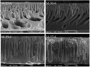 | ||
| Fig. 1 Cross-section morphology of PES porous membrane prepared with different polymer concentration. | ||
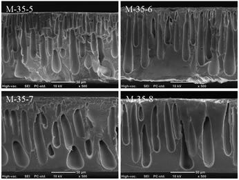
At a certain polymer concentration, the morphology of PES porous membranes was tuned via varying the SPEEK content. The cross-section morphologies of PES porous membranes prepared from different SPEEK content were shown in Fig. 2. The SPEEK content in the polymer increased from 5% to 8%. In this system, the low miscibility between PES and SPEEK could affect the thermodynamic properties of cast solution and further played a significant role on the final morphology and performance of resulted membranes.29 Due to the excellent hydrophilicity, the solvent molecules can diffuse more easily into the solvent/non-solvent interface, favouring the formation of porous skin layer. This porous skin layer was beneficial to the diffusion of more solvent into the cast solution, and thus the pores with similar structure to the skin layer were formed inside the membrane.30 In addition, the organic networks formed by the strong interaction between the sulfonic groups of SPEEK also favoured the formation of sponge-like pores. Therefore, with increasing the SPEEK content in the polymer, the membrane structure was prone to transfer from finger-like pores to spongy-like pores.
Transmission electronic microscopy (TEM) was carried out to investigate the distribution of negatively charged sulfonic groups from SPEEK on the cross-section of PES porous membrane M-35-6. As shown in Fig. 3, the dark spots were ascribed to clusters formed by the interaction between Pb2+ and negatively charged sulfonic groups of SPEEK, showing the uniform distribution of charged SPEEK on the cross-section of PES porous membrane.
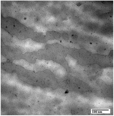 | ||
Fig. 3 Distribution of charged groups of prepared PES porous membrane M-35-6 (with a Mag. of 200![[thin space (1/6-em)]](https://www.rsc.org/images/entities/char_2009.gif) 000). 000). | ||
Mechanical property
Mechanical property is an important parameter of evaluating the membranes. As indicated in Fig. 4, the tensile strength and Young's modulus of PES porous membranes decreased slightly with increasing the SPEEK content in the cast solution. As discussed above, the addition of SPEEK was benefit to the formation of spongy-like pores. The thinner pore wall further weakens the inter-connecting force of the pores. Thus, the mechanical property of the prepared membranes declined slightly when the SPEEK content increased.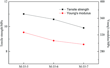 | ||
| Fig. 4 Tensile strength and Young's modulus of PES porous membranes prepared with different SPEEK content. | ||
Pure water flux
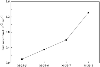
As a criterion of average pore size, the pure water flux of prepared membranes was measured at a certain pressure to link the average pore size of membrane with their morphology. As reported in Fig. 5, the pure water flux of PES porous membranes decreased as the polymer concentration increased. This was due to the formation of the denser skin layer with the polymer concentration increased, which enhanced mass transfer resistance, and consequently lowered the pure water flux. The pure water flux of PES porous membranes prepared with different SPEEK content was shown in Fig. 6. With the addition of SPEEK in the cast solution, the porous skin layer was formed, which increased the pure water flux. Thus, the average pore size can be considered to exhibit the same change trend.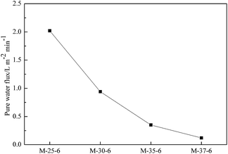 | ||
| Fig. 5 Pure water flux of PES porous membranes prepared from polymer solutions with different concentration. | ||
Vanadium permeability
In a VFB, vanadium ions transport across the membranes will induce the self-discharge and capacity fading. Thus, the permeability of different vanadium ions will have great effect on the VFB single cell performance. As published in the previous literature, the permeability of various vanadium ions is in the order of V2+ > VO2+> VO2+> V3+.31 Due to the fact that V2+ can easily be oxidized by the oxygen gas in air, the permeability of VO2+ was usually detected to link the ions selectivity of membranes with their morphology. As indicated in Fig. 7, the permeability of VO2+ decreased with increasing the polymer concentration. As the polymer concentration increasing, the skin layer of membranes became thicker, which limited the transport of VO2+ across the membrane. Fig. 8 showed the permeability of VO2+ through PES porous membranes prepared from different SPEEK content. The permeability of VO2+ increased with the increased SPEEK content. This was due to the more continuous spongy-like pores induced by the increase of SPEEK content. For example, the permeability of VO2+ increased from 1.05 × 10⁻¹² m2 s−1 to 5.48 × 10⁻¹² m2 s−1 with the SPEEK content increasing from 5% to 6%. The greater liquid absorbility of spongy-like pore was benefit for the ions conductivity of electrolytes, improving the permeability of VO2+. The permeability change is reasonable since the permeability of VO2+ is largely related to the average pore size of prepared membranes. In this system, the permeability of VO2+ of PES porous membrane is comparable than that of Nafion115.14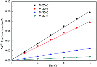 | ||
| Fig. 7 VO2+ concentration in the deficiency side of the diffusion cell with PES porous membrane prepared with different polymer concentration. | ||
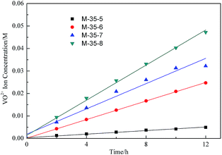 | ||
| Fig. 8 VO2+ concentration in the deficiency side of the diffusion cell with PES porous membrane prepared with different SPEEK content. | ||
Area resistance
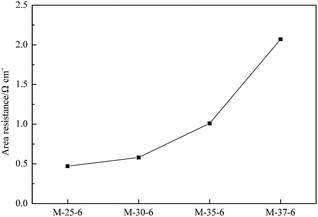
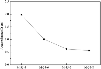
The area resistance of a membrane was closely related to the ion conductivity and finally determined the internal resistance of a battery. Based on the Ohmic law, the resistance is inversely proportional to its cross-section area. Assuming that the resistivity of proton transporting in the solution and membrane is constant, the area resistance of a membrane will increase with the decrease in the cross-section area induced by the decreased pore size. The area resistance of PES membranes prepared with different polymer concentration was indicated in Fig. 9. A denser skin layer can be formed due to the increased polymer concentration, which lowered the cross-section area of pores, and thus a higher area resistance can be obtained. In addition, Fig. 10 showed the area resistance of PES membranes prepared with different SPEEK content. The addition of SPEEK was benefit to the formation of porous skin layer. Meanwhile, the increased number of spongy-like pores and the increased pore size favoured the proton transport, and thus the area resistance decreased.Single cell performance
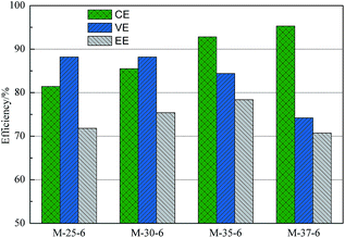
VFB single cell performance of membranes prepared from different polymer concentration was demonstrated in Fig. 11. With the polymer concentration increasing, the columbic efficiency (CE), which is determined by the ratio of a cell's discharge capacity to its charge capacity, increased from 81.4% to 95.3%. Meanwhile, the voltage efficiency (VE), which is defined as the ratio of a cell's mean discharge voltage divided by its mean charge voltage, decreased from 88.2% to 77.4%. As a result, the energy efficiency (EE) first increased and then decreased. As analyzed above, with the polymer concentration increasing, the skin layer of PES porous membranes became denser, which lowered the permeability of vanadium ions, and thus a higher CE can be obtained. At the same time, the proton permeability of membranes decreased with the increased polymer concentration, which enhanced the area resistance and thus lowered the VE.Fig. 12 showed the performance of VFB assembled with membranes prepared from the casting solution with addition of different SPEEK content. It can be seen that as the SPEEK content in the polymer increasing, the CE of membranes decreased from 96.3% to 82.8%, while the VE increased from 66.5% to 88.2%. Accordingly, the EE first increased and then decreased. As discussed above, with the increased SPEEK content, the number of spongy-like pore increased and the pore size increased, which improved the permeability of vanadium ions, and therefore a lower CE was obtained. Meanwhile, the proton permeability increased with increasing the SPEEK content, lowering the area resistance of membranes, and therefore a high VE can be achieved. As a result, when the polymer concentration is 35% and the SPEEK content in the polymer is 6%, the PES porous membrane showed optimized performance, showing CE of 92.8% and EE of 78.4% at a current density of 80 mA cm−2, The VFB performance is comparable to that of Nafion, but at a much lower cost.
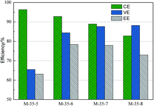 | ||
| Fig. 12 VFB performance of PES porous membranes prepared with different SPEEK content in the polymer. | ||
Stability and cycle life
PES porous membrane M-35-6 and Nafion115 were immersed into 0.15 M V5+ solution for 20 days to investigate the oxidation stability of the prepared membrane. As shown in Fig. 13a, VO2+ concentration change in V5+ solution involving PES membrane M-35-6 and Nafion115 was kept at the initial value of 0.0014 M, and no obvious change was found. SEM was also carried out on the cross-section morphology of PES porous membrane after treatment. As shown in Fig. 13b, compared with the initial membrane above, there was no obviously change in the cross-section morphology. Moreover, mechanical properties of PES porous membrane M-35-7 after treatment were measured to investigate the mechanical stability of the prepared membranes. The membrane M-35-7 after treatment exhibited tensile strength of 10.02 MPa and Young's modulus of 305 MPa (initial: tensile strength of 9.89 MPa and Young's modulus of 297 MPa), and no obvious decline was observed. These results indicated that the PES porous membrane and Nafion115 in the V5+ solution both exhibited the excellent oxidation stability and mechanical stability.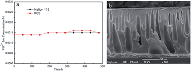 | ||
| Fig. 13 (a) VO2+ concentration change of electrolyte solution involving PES membrane M-35-6 and Nafion115 as a function of time; (b) cross-section morphology of M-35-6 after 20 days. | ||
During the charge–discharge process, many factors will lead to the performance fading of PES porous membrane, including the degradation of membrane caused by the oxidation of V5+, the lower mechanical stability induced by the internal stress, and the membrane damage resulting from the external physical effect such as the electrolyte washing. To further evaluate the cycling performance of membrane, VFB single cell assembled with M-35-6 was cycled at a current density of 80 mA cm−2. As illustrated in Fig. 14a, the CE of the VFB remained stable at around 92% over 200 cycles and the EE remained about 78%, suggesting the good stability of the membranes. In addition, SEM was performed on the cross-section morphology of membrane after the cycling test. As shown in Fig. 14b, no collapse of pores in sublayer was observed. Overall, the PES porous membrane exhibited excellent chemical and mechanical stability under the practical VFB conditions.
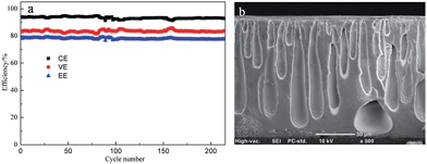 | ||
| Fig. 14 (a) cycling performance of VFB assembled with PES porous membrane M-35-6 at a current density of 80 mA cm−2; (b) cross-section morphology after the cycling test. | ||
Conclusions
In this work, PES porous membranes with tunable morphology were prepared by introducing hydrophilic SPEEK in the cast solution. The cross-section morphology of membranes was characterized via TEM and SEM. With increasing the polymer concentration in the cast solution, the number of macrovoids gradually decreased and the finger-like pores became larger. With the addition of SPEEK in the cast solution, the membrane structure tuned from finger-like to spongy-like pores and the pore size becomes larger. As a consequence, the VFB assembled with PES porous membranes with optimized morphology showed CE of 92.8% and EE of 78.4% at a current density of 80 mA cm−2. Moreover, PES porous membrane exhibited excellent oxidation stability in V5+ solution and stable performance during 200 cycles. Therefore, PES porous membrane with tunable morphology showed quite good potential usage in VFB.Experimental
Materials
Sulfonated poly(ether ether ketone) (SPEEK) was synthesized by direct sulfonation of PEEK with sulfuric acid at 70 °C for 2 h, as reported elsewhere.32 The degree of sulfonation obtained by 1H NMR is around 0.8.32 Poly(ether sulfone) (PES) with viscosity of 0.58 was obtained from Changchun Jilin University Special Plastic Engineering Research. The N,N-dimethylacetamide (DMAc) was purchased from Tianjin Damao Chemical Reagent Factory.Membrane preparation
The PES porous membranes were prepared by the phase inversion technique from a solution containing certain weight ratio of PES and SPEEK dissolved in DMAc. Then the solution was cast onto a clean glass plate at room temperature with humidity less than 40% to avoid the penetration of water vapour into the polymer solution. After evaporation for 10 s, the plate was immersed into water to form the PES porous membranes (denoted as M-x-y, where x and y are the polymer concentration in the cast solution and the SPEEK content in the polymer, respectively). The thickness of the prepared membranes was 160 ± 5 μm.Scanning electronic microscopy (SEM)
The cross-section morphology of prepared membranes was characterized by SEM (JEOL 6360LV, Japan). All the samples were obtained by breaking in liquid nitrogen.Transmission electronic microscopy (TEM)
The distribution of negatively charge SPEEK on the cross-section of membrane was characterized by TEM (JEM-200EX, JEOL). All the samples were stained with 0.5 M Pb2+ and fixed in epoxy before cut into thin slice samples.Mechanical property
The tensile strength and Young's modulus of the membranes were measured using SHIMADIU AG-I 1KN at the test speed of 5 mm min−1, the size of specimen was 7 × 1 cm. For each testing reported, at least three measurements were taken and average value was calculated.Pure water flux
Pure water flux of prepared membranes was conducted in a stainless steel dead-end pressure cell with the effective area of the membrane of 19.6 cm2. After filing the cell with water, the cell was pressurized with nitrogen and then kept at a pressure of 2.0 MPa. Permeate samples were collected in cooled flasks as a function of time, weighted and analyzed. The pure water flux of membranes was calculated by the following equation:where J is pure water flux, m is the water mass, ρ is the water density, s is the effective area of tested membrane, and t is the water permeation time.
Vanadium permeability
Vanadium permeability was measured by a diffusion cell described as follows. The left cell was filled with 1.5 M VOSO4 in 3 M H2SO4 solution, while the right cell was filled with 1.5 M MgSO4 in 3 M H2SO4 solution. Both sides were vigorously stirred to avoid concentration polarization. Samples from the right cell were collected at regular time intervals. The concentration of VO2+ was detected by a UV-vis spectrometer (JASCO, FT-IR 4100, Japan).Area resistance
A conductivity cell was utilized to measure the area resistance of the membrane. The cell was filled with 0.5 M H2SO4 in each compartment separated by a membrane with the effective area of 1 cm2. The electric resistance was characterized by electrochemical impedance spectroscopy (EIS) over a frequency range from 1 kHz to 1 MHz. The area resistance was calculated by the following equation:| r = (r2 − r1) × s |
VFB single cell performance
A VFB single cell was fabricated by sandwiching a membrane with two pieces of carbon felt electrodes, clamped by two pieces of polar plates. All these components were fixed between two pieces of stainless plates. The effective area of the membrane was 9 cm2. 30 mL of 1.5 M V2+/V3+ in 3.0 M H2SO4 solutions and of 1.5 M VO2+/VO2+ in 3.0 M H2SO4 solutions, serving as negative and positive electrolytes respectively, were cyclically pumped into the corresponding half-cell via airtight pine lines. The charge–discharge test of the VFB was conducted by Arbin BT 2000 at a current density of 80 mA cm−2. The cut-off voltage for charge and discharge was set between 1.65 V and 0.8 V to avoid the corrosion of carbon felt electrodes and graphite polar plates.Stability test
The chemical stability of membranes was investigated by the method described in our previous study.19 A 3 cm × 3 cm PES porous membrane was immersed into 60 mL electrolyte solution (0.15 M VO2+ in 3.0 M H2SO4 solutions) at 40 °C. A 3 mL electrolyte was collected from the bottle at a regular time during the test. The concentration of VO2+ was determined by a UV-vis spectrometer (JASCO, FT-IR 4100, Japan).To further investigate the oxidation stability of PES porous membrane under the practical conditions, the charge–discharge cycle test was carried out at a current density of 80 mA cm−2.
Notes and references
- W. Wang, Q. T. Luo, B. Li, X. L. Wei, L. Y. Li and Z. G. Yang, Adv. Funct. Mater., 2013, 23, 970–986 CrossRef CAS PubMed.
- B. Dunn, H. Kamath and J. M. Tarascon, Science, 2011, 334, 928–935 CrossRef CAS PubMed.
- P. X. Han, X. G. Wang, L. X. Zhang, T. S. Wang, J. H. Yao, C. S. Huang, L. Gu and G. L. Cui, RSC Adv., 2014, 4, 20379–20381 RSC.
- Z. G. Yang, J. L. Zhang, M. C. W. Kintner-Meyer, X. C. Lu, D. W. Choi, J. P. Lemmon and J. Liu, Chem. Rev., 2011, 111, 3577–3613 CrossRef CAS PubMed.
- M. Skyllas-Kazacos, M. H. Chakrabarti, S. A. Hajimolana, F. S. Mjalli and M. Saleem, J. Electrochem. Soc., 2011, 158, R55–R79 CrossRef CAS PubMed.
- X. F. Li, H. M. Zhang, Z. S. Mai, H. Z. Zhang and I. Vankelecom, Energy Environ. Sci., 2011, 4, 1147–1160 CAS.
- M. Skyllas-Kazacos, M. Rychcik, R. G. Robins, A. G. Fane and M. A. Green, J. Electrochem. Soc., 1986, 133, 1057–1058 CrossRef CAS PubMed.
- P. X. Han, Y. H. Yue, Z. H. Liu, W. Xu, L. X. Zhang, H. X. Xu, S. M. Dong and G. L. Cui, Energy Environ. Sci., 2011, 4, 4710–4717 CAS.
- P. X. Han, H. B. Wang, Z. H. Liu, X. Chen, W. Ma, J. H. Yao, Y. W. Zhu and G. L. Cui, Carbon, 2011, 49, 693–700 CrossRef CAS PubMed.
- C. P. de Leon, A. Frias-Ferrer, J. Gonzalez-Garcia, D. A. Szanto and F. C. Walsh, J. Power Sources, 2006, 160, 716–732 CrossRef PubMed.
- B. Schwenzer, J. L. Zhang, S. Kim, L. Y. Li, J. Liu and Z. G. Yang, ChemSusChem, 2011, 4, 1388–1406 CrossRef CAS PubMed.
- Q. T. Luo, H. M. Zhang, J. Chen, P. Qian and Y. F. Zhai, J. Membr. Sci., 2008, 311, 98–103 CrossRef CAS PubMed.
- S. B. Sang, Q. M. Wu and K. L. Huang, J. Membr. Sci., 2007, 305, 118–124 CrossRef CAS PubMed.
- Z. S. Mai, H. M. Zhang, X. F. Li, C. Bi and H. Dai, J. Power Sources, 2011, 196, 482–487 CrossRef CAS PubMed.
- S. H. Zhang, C. X. Yin, D. B. Xing, D. L. Yang and X. G. Jian, J. Membr. Sci., 2010, 363, 243–249 CrossRef CAS PubMed.
- D. B. Xing, S. H. Zhang, C. X. Yin, C. Yan and X. Jian, Mater. Sci. Eng., B, 2009, 157, 1–5 CrossRef CAS PubMed.
- H. Z. Zhang, H. M. Zhang, X. F. Li, Z. S. Mai and J. L. Zhang, Energy Environ. Sci., 2011, 4, 1676–1679 CAS.
- W. P. Wei, H. M. Zhang, X. F. Li, H. Z. Zhang, Y. Li and I. Vankelecom, Phys. Chem. Chem. Phys., 2013, 15, 1766–1771 RSC.
- Y. Li, H. M. Zhang, X. F. Li, H. Z. Zhang and W. P. Wei, J. Power Sources, 2013, 233, 202–208 CrossRef CAS PubMed.
- W. J. Lau and A. F. Ismail, Desalination, 2009, 249, 996–1005 CrossRef CAS PubMed.
- G. Arthanareeswaran, D. Mohan and M. Raajenthiren, Appl. Surf. Sci., 2007, 253, 8705–8712 CrossRef CAS PubMed.
- A. K. Holda, B. Aernouts, W. Saeys and I. F. J. Vankelecom, J. Membr. Sci., 2013, 442, 196–205 CrossRef CAS PubMed.
- Y. Li, H. M. Zhang, H. Z. Zhang, J. Y. Cao, W. X. Xu and X. F. Li, J. Membr. Sci., 2014, 454, 478–487 CrossRef CAS PubMed.
- G. Arthanareeswaran, P. Thanikaivelan and M. Raajenthiren, J. Appl. Polym. Sci., 2010, 116, 995–1004 CAS.
- C. J. Zhao, Z. Wang, D. W. Bi, H. D. Lin, K. Shao, T. Z. Fu, S. L. Zhong and H. Na, Polymer, 2007, 48, 3090–3097 CrossRef CAS PubMed.
- W. R. Bowen, S. Y. Cheng, T. A. Doneva and D. L. Oatley, J. Membr. Sci., 2005, 250, 1–10 CrossRef CAS PubMed.
- S. Z. Ren, G. Q. Sun, C. N. Li, Z. M. Wu, W. Jin, W. M. Chen, Q. Xin and X. F. Yang, Mater. Lett., 2006, 60, 44–47 CrossRef CAS PubMed.
- S. S. Lim, W. R. W. Daud, J. M. Jahim, M. Ghasemi, P. S. Chong and M. Ismail, Int. J. Hydrogen Energy, 2012, 37, 11409–11424 CrossRef CAS PubMed.
- G. Q. Wei, L. Xu, C. D. Huang and Y. X. Wang, Int. J. Hydrogen Energy, 2010, 35, 7778–7783 CrossRef CAS PubMed.
- S. Liu, L. Zhou, P. J. Wang, L. S. Zhang, Z. G. Shao and B. L. Yi, J. Mater. Chem., 2012, 22, 20512–20519 RSC.
- C. X. Sun, J. Chen, H. M. Zhang, X. Han and Q. T. Luo, J. Power Sources, 2010, 195, 890–897 CrossRef CAS PubMed.
- P. X. Xing, G. P. Robertson, M. D. Guiver, S. D. Mikhailenko, K. P. Wang and S. Kaliaguine, J. Membr. Sci., 2004, 229, 95–106 CrossRef CAS PubMed.
| This journal is © The Royal Society of Chemistry 2014 |

