A comparison of carbon supports in MnO2/C supercapacitors†
Chao Weia,
Pooi See Leea and
Zhichuan Xu*abc
aSchool of Materials Science and Engineering, Nanyang Technological University, 50 Nanyang Avenue, Singapore 639798, Singapore. E-mail: xuzc@ntu.edu.sg
bEnergy Research Institute, Nanyang Technological University, 50 Nanyang Avenue, Singapore 639798, Singapore
cSolar Fuels Lab, Nanyang Technological University, 50 Nanyang Avenue, Singapore 639798, Singapore
First published on 8th July 2014
Abstract
This article presents a comparison of three typical carbon supports, carbon nanotubes (CNTs), reduced graphene oxide (rGO), and acetylene black (AB), with regards to their performance in MnO2 supercapacitors. To exclude the influence of MnO2, uniform-sized MnO2 nanoflakes with a width of ∼50 nm were used to fabricate three MnO2/C composites. The working electrodes were prepared using a consistent procedure to keep all three types of MnO2/C electrodes in the same configuration. The influence of these three carbon supports on capacitive performance and cyclability was studied. In particular, the capacitance contribution of carbon supports was subtracted from the overall capacitance. The contribution from MnO2 was compared among these three types of composites and it was found that rGO could enhance the capacitive performance of MnO2 at slow scan rates. However, MnO2/CNTs and MnO2/AB exhibited better capacitive performance at high rates and better stability.
Introduction
The limited fossil fuel resources and increasing environmental problems have stimulated great interest in sustainable energy resources. To relate the sustainable energy resources to our daily life, efficient energy storage and conversion technologies are highly demanded for smart grid, zero-emission transport, and portable devices.1 Among these technologies, supercapacitors are a class of attractive energy storage devices due to their high power density, low cost, high safety, and long lifetime.2 According to the charge storage mechanism, there are two types of supercapacitors. One is the electrical double layer capacitors (EDLCs), which use carbon as electrode materials. EDLCs often give high power density, but low energy density.3 The other is the pseudocapacitors, which use redox materials like metal oxides4 and conducting polymers5 as active electrode materials. Depending on the active materials, pseudocapacitors can achieve fairly high energy density and power density.6,7Manganese dioxide (MnO2) is a very popular redox capacitor material and the related research has been intensively conducted in the past few years due to the increasing interest in the field of energy storage and conversion.8–10 MnO2 is a promising electrode material for low cost, high energy density supercapacitors because of its abundance in the earth and high specific energy capacity.11,12 MnO2 is also environmental benign due to its low toxicity. Thus it has a great potential to be widely used in energy devices. The theoretical specific capacitance of MnO2 is nearly 1400 F g−1 if all manganese can be involved in the redox reaction (one-electron redox).10 However, to have all manganese participated in the redox reaction is difficult because the redox reaction happens only at the surface region of MnO2. It therefore stimulated a great interest to innovate nanosized MnO2 materials to increase the specific surface area. To date, various methods have been reported to synthesize nanosized MnO2, including co-precipitation,13,14 sol–gel,15 electro-deposition,16,17 hydrothermal,18 and etc. The use of MnO2 nanomaterials has given significant improvements in capacitance.19
However, it should be noted that MnO2 has frequently been combined with carbon support to be used in supercapacitors. This is because MnO2 is not conductive. Various carbon support materials have been used in MnO2 supercapacitors.20,21 The popular carbon supports include carbon nanotubes (CNTs), graphene, carbon black (CB), etc. These carbon supports are usually mixed with MnO2 through different approaches, depending on the synthetic methods of MnO2. For example, some approaches are able to synthesize MnO2/C composites by one step protocol,10 while some others use extra steps to make MnO2/C electrodes.21 It has been well-established in literatures that the carbon supports are influential to enhancing the performance of MnO2 supercapacitors.19,20 However, the various reported MnO2/C composites are made from different approaches and those composites are quite different in composition, morphology, MnO2 materials, mass ratio, and other parameters. As a result, comparisons on the influence of these carbon supports on the MnO2 supercapacitor performance have been rare.
Here we present a rational comparison of three typical carbon supports, carbon nanotubes, graphene, and carbon black, with regards to their performance in MnO2 supercapacitors. We employed uniform-sized MnO2 nanoflakes, which served as a standard active material for three carbon supports. The electrode preparation followed the standard method to keep all three types of MnO2/C electrodes same in configuration. The influence of these three carbon supports on capacitive performance and cyclability was compared.
Experimental
Synthesis of MnO2 nanoflakes
MnO2 nanoflakes were synthesized by modifying a recipe.22 In a typical synthesis, an aqueous solution containing 0.05 M potassium permanganate (KMnO4) and 0.02 M cetrimonium bromide (CTAB) was heated to boiling in two minutes. The solution turned to dark brown immediately. The solution was kept boiling for 30 minutes. The product was washed with water and acetone by centrifugation at 8000 rpm for three times to remove the surfactant.Carbon materials
Three carbon materials were selected for this study. Carbon black (acetylene black, Alfa Aesar) and multiwall carbon nanotubes (MWNTs, Sigma-Aldrich) were used as purchased without any treatment. Reduced graphene oxide (rGO) was prepared by a modified Hummer's method.23,24 All chemicals for rGO synthesis were purchased from Sigma-Aldrich. In a typical synthesis, 1.5 g graphite powder was suspended into 20 ml 98% H2SO4 with 1.25 g K2S2O8 and 1.25 g P2O5. The suspension was heated to 80 °C and kept at this temperature for 6 hours. The resulting pre-oxidized graphite was washed with deionized water by filtration and dried in vacuum oven. The powder was then suspended in 80 ml 98% H2SO4 with 7.5 g KMnO4 and treated at 40 °C for 2 hours. Subsequently, the solution was cooled down to ∼0 °C using ice bath and then 150 ml of deionized water and 10 ml of H2O2 were slowly added into the solution. The yellow solution was washed with 10% HCl. To remove the Cl− ions, the material was washed with the large amount of deionized water until neutral pH was achieved. The powders were finally thermally treated to produce reduced graphene oxide (rGO) at 1050 °C.Carbon loading
A solution of carbon material (∼0.5 mg L−1) was prepared by sonicating the selected carbon supports (here carbon black, MWCNT, or rGO) in ethanol for 3 hours. Afterwards, a solution of MnO2 nanoflakes with desired concentration was added drop-wise into the carbon solution and the mixture was further sonicated for 2 hours. The MnO2/C precipitation was collected by centrifuging for 10 min at 9500 rpm. The MnO2/C was dried under vacuum for further use. In order to precisely control the mass loading, the concentration of MnO2 solution used here was determined by ICP. TEM images were obtained on a TEM JEOL 2010 operated at 200 kV.Electrochemical measurement
The working electrodes were prepared by a conventional method. Typically, as-prepared MnO2/C composites and polyvinylidene difluoride (PVDF) were mixed with a mass ratio of 90![[thin space (1/6-em)]](https://www.rsc.org/images/entities/char_2009.gif) :
:![[thin space (1/6-em)]](https://www.rsc.org/images/entities/char_2009.gif) 10 and dispersed in N-methyl pyrrolidone (NMP). The resulting slurry was pasted onto nickel foam substrate (1 cm × 1 cm) with a spatula. The total weight of the active material for each sample was controlled at ∼1 mg. After drying at 75 °C for 12 hours, the electrode was pressed at 10 MPa. All electrochemical measurements were carried out on Solartron Electrochemical Interface 1287 and Impedance Analyzer 1260 using typical three-electrode configuration, where a platinum foil, a saturated calomel electrode (SCE), and the prepared composite electrodes served as counter, reference, and working electrodes, respectively. The electrolyte was 1 M Na2SO4 aqueous solution. Cyclic voltammetry (CV) was recorded at different scan rates of 5, 10, 20, 50, 100, 200, and 500 mV s−1. The impedance measurements were carried out in the frequency range from 100 kHz to 0.1 Hz at open circuit potential with an AC perturbation of 5 mV. Galvanostatic charge/discharge curves were measured at different current densities of 0.5, 1, 1.5, and 3 A g−1 to evaluate the power density and energy density. The cyclability test was conducted by Galvanostatic charge/discharge approach at the current density of 3 A g−1. The potential window in the range of −0.1 to 0.9 V (vs. SCE) was used in all the measurements.
10 and dispersed in N-methyl pyrrolidone (NMP). The resulting slurry was pasted onto nickel foam substrate (1 cm × 1 cm) with a spatula. The total weight of the active material for each sample was controlled at ∼1 mg. After drying at 75 °C for 12 hours, the electrode was pressed at 10 MPa. All electrochemical measurements were carried out on Solartron Electrochemical Interface 1287 and Impedance Analyzer 1260 using typical three-electrode configuration, where a platinum foil, a saturated calomel electrode (SCE), and the prepared composite electrodes served as counter, reference, and working electrodes, respectively. The electrolyte was 1 M Na2SO4 aqueous solution. Cyclic voltammetry (CV) was recorded at different scan rates of 5, 10, 20, 50, 100, 200, and 500 mV s−1. The impedance measurements were carried out in the frequency range from 100 kHz to 0.1 Hz at open circuit potential with an AC perturbation of 5 mV. Galvanostatic charge/discharge curves were measured at different current densities of 0.5, 1, 1.5, and 3 A g−1 to evaluate the power density and energy density. The cyclability test was conducted by Galvanostatic charge/discharge approach at the current density of 3 A g−1. The potential window in the range of −0.1 to 0.9 V (vs. SCE) was used in all the measurements.
Results and discussion
Capacitance of carbon supports
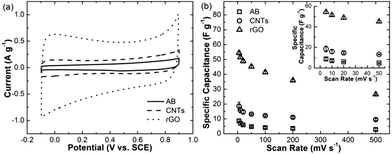
Fig. 1a shows the representative cyclic voltammograms of carbon supports, carbon nanotubes (CNTs), graphene (rGO), and carbon black, at the scan rate of 10 mV s−1. The CVs of carbon nanotubes and carbon black are similar in shape, giving a typical feature of double layer capacitor. Graphene gave a larger CV than the other two carbons. It is partially due to the larger specific surface area of graphene. The defects and remaining functional groups also contributed some pseudo-capacitance. The typical pseudo-capacitance features include the deviation from rectangularity and the appearance of polarized peaks at the two sides of the CV, which is consistent with the reported results.20,25 Fig. 1b shows the specific capacitance of these carbon supports at the different scan rate from 5 to 500 mV s−1. Each data point and its error bar were obtained by three independent measurements. rGO showed the higher specific capacitance than CNTs and AB, especially at the low scan rates. For example, rGO gave ∼54.4 F g−1 at 5 mV s−1, which is nearly three times higher than CNTs (∼18.5 F g−1) and seven times higher than AB (∼8.7 F g−1). Limited by charge transportation at the high rate, the capacitance of these carbons drops with the increase of scan rate. The specific capacitance of rGO dropped about 50% from ∼54.4 F g−1 to ∼26.5 F g−1 as the scan rate increased from 5 to 500 mV s−1. CNTs and AB gave similar drops in their capacitance.Capacitive performance of MnO2/C composites
MnO2/C composites were synthesized by mixing MnO2 nanoflakes with AB, CNTs, and rGO. By varying the mass ratio of MnO2![[thin space (1/6-em)]](https://www.rsc.org/images/entities/char_2009.gif) :
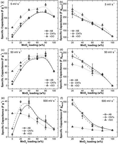
:![[thin space (1/6-em)]](https://www.rsc.org/images/entities/char_2009.gif) C, the composition of each MnO2/C composite was given at 20, 40, 60, and 80 wt% of MnO2. Their specific capacitance was recorded using cyclic voltammetry method in 1 M Na2SO4 at room temperature. Fig. 2a shows the specific capacitance of MnO2/C with different MnO2 mass loading at 5 mV s−1. 0 wt% refers to the pure carbon supports and 100 wt% refers to the electrodes with only MnO2 on nickel foam. The specific capacitance value in Fig. 2a was normalized by the total mass of MnO2 and the carbon support. The overall trend for three types of MnO2/C composites is the same, i.e. the specific capacitance increases with the increase of MnO2 loading. This is because of the increase of active component MnO2 in the composite, which mainly contributes the overall capacitance. Among these loading amount, 80 wt% of MnO2 gave the highest capacitance for all MnO2/C composites. The specific capacitance of MnO2/rGO with 80 wt% MnO2 (MnO2
C, the composition of each MnO2/C composite was given at 20, 40, 60, and 80 wt% of MnO2. Their specific capacitance was recorded using cyclic voltammetry method in 1 M Na2SO4 at room temperature. Fig. 2a shows the specific capacitance of MnO2/C with different MnO2 mass loading at 5 mV s−1. 0 wt% refers to the pure carbon supports and 100 wt% refers to the electrodes with only MnO2 on nickel foam. The specific capacitance value in Fig. 2a was normalized by the total mass of MnO2 and the carbon support. The overall trend for three types of MnO2/C composites is the same, i.e. the specific capacitance increases with the increase of MnO2 loading. This is because of the increase of active component MnO2 in the composite, which mainly contributes the overall capacitance. Among these loading amount, 80 wt% of MnO2 gave the highest capacitance for all MnO2/C composites. The specific capacitance of MnO2/rGO with 80 wt% MnO2 (MnO2![[thin space (1/6-em)]](https://www.rsc.org/images/entities/char_2009.gif) :
:![[thin space (1/6-em)]](https://www.rsc.org/images/entities/char_2009.gif) C = 80
C = 80![[thin space (1/6-em)]](https://www.rsc.org/images/entities/char_2009.gif) :
:![[thin space (1/6-em)]](https://www.rsc.org/images/entities/char_2009.gif) 20) is ∼165.1 F g−1, while the specific capacitance of MnO2/CNTs and MnO2/AB with the same composition are ∼134.1 and ∼130.1 F g−1, respectively. In general, MnO2/rGO showed higher capacitance than MnO2/CNTs and MnO2/AB at all compositions. MnO2/CNTs and MnO2/AB exhibited similar capacitance at 40, 60, and 80 wt% of MnO2. At 20 wt%, the specific capacitance of MnO2/CNTs is slightly higher than MnO2/AB. The better performance of MnO2/rGO is probably due to the capacitance contribution of rGO. As shown in Fig. 1b, rGO contributes a capacitance of ∼54 F g−1 at 5 mV s−1.
20) is ∼165.1 F g−1, while the specific capacitance of MnO2/CNTs and MnO2/AB with the same composition are ∼134.1 and ∼130.1 F g−1, respectively. In general, MnO2/rGO showed higher capacitance than MnO2/CNTs and MnO2/AB at all compositions. MnO2/CNTs and MnO2/AB exhibited similar capacitance at 40, 60, and 80 wt% of MnO2. At 20 wt%, the specific capacitance of MnO2/CNTs is slightly higher than MnO2/AB. The better performance of MnO2/rGO is probably due to the capacitance contribution of rGO. As shown in Fig. 1b, rGO contributes a capacitance of ∼54 F g−1 at 5 mV s−1.
To investigate the influence of rGO and the other two carbon supports, the capacitance contributions of carbon supports were subtracted from the composite capacitance. The specific capacitances at 5 mV s−1 purely from the contribution of MnO2 are shown in Fig. 2b. It can be seen that in general MnO2 supported on rGO gave higher capacitance than MnO2 supported on the other two carbon supports. CNTs and AB showed similar influence on the performance of supported MnO2. At 20 wt% of MnO2, supported MnO2 exhibited highest capacitance. MnO2 supported on rGO, CNTs, and AB gave specific capacitance of ∼310.2, 292.4, and 274.5 F g−1, respectively. As more MnO2 was made into the composites, the specific capacitance of supported MnO2 dropped. From 20 wt% to 80 wt%, the capacitance drop was nearly in a linear relationship with composition. At 80 wt%, the specific capacitance of supported MnO2 were ∼192.8, ∼163.5, and ∼160.5 F g−1 for MnO2/rGO, MnO2/CNTs, and MnO2/AB, respectively. The capacitance drop for all three types of MnO2/C composites is nearly 50% from 20 to 80 wt% of MnO2. The pure MnO2 supported on nickel foam (100 wt%) gave the lowest specific capacitance. The pure contribution from MnO2 shown in Fig. 2b indicates that carbon supports are essential and influential to the performance of MnO2. If more carbon supports and less MnO2 were made into the composites, higher specific capacitance of supported MnO2 can be achieved.
The trend of specific capacitance of MnO2/C composites at the scan rate of 50 mV s−1 is similar to that at 5 mV s−1. Fig. 2c shows the specific capacitance of three types of composites normalized by the total mass of MnO2 and carbon. Again, MnO2/rGO showed better performance than the other two MnO2/C composites. However, this superiority of rGO is not as remarkable as it showed at 5 mV s−1. For example, MnO2/rGO with 20 wt% MnO2 gave a specific capacitance of ∼71.8 F g−1, which is ∼10 and ∼20 F g−1 more than MnO2/CNTs and MnO2/AB. As the weight percentage of MnO2 increased to 80 wt%, the capacitance of MnO2/rGO, MnO2/CNTs, and MnO2/AB are quite similar. All are around ∼95 F g−1. On the other hand, after subtracting the capacitance contribution of carbons, the specific capacitance of MnO2 purely from the supported MnO2 exhibited a change. At 50 mV s−1, the highest capacitance contribution from MnO2 was given by MnO2/CNTs with 20 wt% of MnO2 as shown in Fig. 2d. 20 wt% MnO2 supported on CNTs gave a specific capacitance of ∼256.1 F g−1. The value for MnO2 supported on AB and rGO are ∼228.1 and ∼178.2 F g−1, respectively. As more MnO2 was made into the composites, the specific capacitance of supported MnO2 decreased. At the mass loading of 40 and 60 wt%, MnO2 supported on CNTs and AB exhibited similar performance in capacitance, while MnO2 supported rGO showed lower performance. This indicates that the charge transportation within the MnO2/rGO probably was not fast as compared to MnO2/CNTs and MnO2/AB. The electrochemical impedance spectra of these composites indicated that the resistance of rGO used here was larger than CNTs and AB (Fig. S3†). It should be noted that rGO has higher specific surface area and higher porosity than AB and CNTs (Fig. S4†). However, the double layer capacitance from carbons gave limited contribution and it was also subtracted for comparing the capacitive contributions from MnO2 supported by three carbons. The high porosity of the rGO electrodes did not show better capacitive behaviour at the high rates. It indicates that the influence of the porosity of carbon supports is very small. The lower conductivity probably is one factor that affected the overall charge transportation efficiency. For all composites, with the increase of the mass loading of MnO2, the electrode resistance increased gradually. This is consistent with the reported result that the non-conductive MnO2 usually lowers the overall conductivity of the composite.21 It should be noticed that all MnO2/C composites here are made without any chemical modification at the interface of MnO2 and carbon supports. Carbon materials here only played the roles of the conducting substrate and the MnO2 support. Although rGO has a remarkable capacitance contribution, the large size of rGO sheets might hinder the transportation of charge species in the electrolyte as rGO is multiple stacked at the solid state. Another reason is that the resistance of rGO composites is higher than others. This is probably because these composites were mixed physically. Without a chemical bonding or interaction between MnO2 and carbon, the resistance would be high.28–30 As the weight percentage of MnO2 increased to 80 wt%, the specific capacitance of supported MnO2 in three types of MnO2/C composites were nearly similar.
At the scan rate of 500 mV s−1, it is interesting to find that the specific capacitance of MnO2/rGO is lower than that of MnO2/CNTs and MnO2/AB no matter how much MnO2 was loaded (Fig. 2e). At this high rate, MnO2/CNTs gave higher capacitance at 20 wt% of MnO2. MnO2/rGO exhibited a similar specific capacitance as pure rGO. However, the specific capacitance of MnO2/rGO dropped significantly as the amount of MnO2 increased more than 20 wt%. Such a trend can be also be found on MnO2/CNTs and MnO2/AB. For MnO2/CNTs, the highest specific capacitance was given by 20 wt%. Then the capacitance dropped as the amount of MnO2 increased. For MnO2/AB, the highest specific capacitance was given by 40 wt%, followed by the 20 wt% sample. At the high loading amount of MnO2 like 60 and 80 wt%, MnO2/CNTs and MnO2/AB showed similar specific capacitance. Fig. 2f shows the specific capacitance of supported MnO2 at 500 mV s−1 after subtracting the contribution of carbons at this scan rate. A remarkable phenomenon can be found on MnO2/rGO composites. For all mass loading of MnO2 from 20 to 80 wt%, MnO2 supported on rGO gave similar capacitance performance, which is nearly same as the MnO2 on nickel foam. It indicates that at a high scan rate rGO may not be able to enhance the performance of MnO2. Its function is similar to nickel current collector. Again, this is probably due to the large size of rGO, which hinders the charge transportation within the electrode.20 On the other hand, we found that CNTs and AB were able to play the role of carbon supports to enhance the performance of MnO2 even at this high scan rate. For example, the capacitance contribution from MnO2 could reach 160.0 and 140.2 F g−1 as 20 wt% of MnO2 were supported on CNTs and AB, respectively. Even at 80 wt% of MnO2, MnO2 supported on CNTs and AB could still gave a contribution of ∼20 F g−1, while those on rGO gave ∼6.8 F g−1.
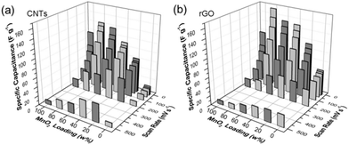
The above results show that AB and CNTs gave similar contribution in supporting MnO2 for enhancing specific capacitance, while rGO can enhance the capacitance much more than AB and CNTs. To demonstrate the capacitance at other scan rates, the average specific capacitance of MnO2/CNTs and MnO2/rGO composites at different scan rates are shown in Fig. 3. At all compositions, MnO2/rGO showed higher capacitance than MnO2/CNTs at slow scan rates. This is consistent with the results in reported literatures.19–21,26 But, at high scan rates like 200 and 500 mV s−1, MnO2/CNTs showed better capacitance. The detailed rate capability analysis is given in the following paragraphs.
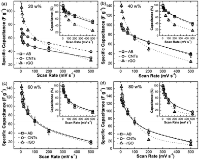
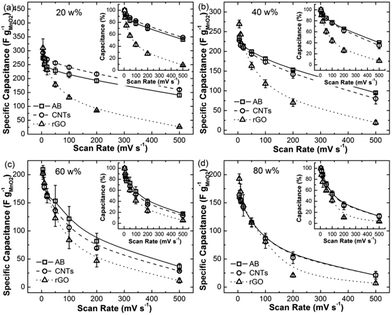
The specific capacitances of three types of MnO2/C composites at different scan rates were plotted in Fig. 4. The capacitance here was normalized by the total mass of MnO2 and carbon. Fig. 4a shows the three types of MnO2/C composites with a loading mass of 20 wt% MnO2. They all exhibited a dropping trend in capacitance as the scan rate increased gradually from 5 to 500 mV s−1. However, MnO2/rGO showed a remarkable drop as compared to the other two composites. In particular, the specific capacitance of MnO2/rGO dropped sharply from ∼105.5 to ∼71.8 F g−1 as the scan rate increased from 5 to 50 mV s−1. The capacitance drop is over 30% (see the inset of Fig. 4a). In contrast, the capacitance drops of MnO2/CNTs and MnO2/AB from 5 to 50 mV s−1 are only ∼16% and ∼20%, respectively. It should be noticed that the specific capacitance of MnO2/rGO at the scan rate of 50 mV s−1 is still higher than that of MnO2/CNTs and MnO2/AB although MnO2/rGO gave the bigger drop. As the scan rate was increased further to 100, 200, and 500 mV s−1, the capacitance of MnO2/rGO dropped to 56%, 43%, and 25% of the highest capacitance obtained at 5 mV s−1. The other two MnO2/C composites gave smaller drops, i.e. as the scan rate reached to 100, 200, and 500 mV s−1, the capacitance of MnO2/CNTs dropped to 79%, 71%, and 54%, while that of MnO2/AB dropped to 75%, 67%, and 49%, respectively. As a result, MnO2/rGO lost its superiority in the specific capacitance at these high scan rates. At 200 mV s−1, MnO2/CNTs gave higher capacitance (∼52.1 F g−1) than MnO2/rGO (∼45.7 F g−1), which in turn is higher than MnO2/AB (∼41.3 F g−1). At 500 mV s−1, MnO2/CNTs again gave the highest capacitance (∼39.6 F g−1) and MnO2/rGO gave the lowest value (∼26.5 F g−1).
Fig. 4b shows the specific capacitance of MnO2/C composites with 40 wt% of MnO2. At the range of 5–50 mV s−1, MnO2/rGO still exhibited higher capacitance than MnO2/CNTs and MnO2/AB. It also gave a faster capacitance drop to 66% of the highest capacitance achieved at 5 mV s−1. Both MnO2/CNTs and MnO2/AB dropped their capacitance to ∼83% of the highest value achieved at 5 mV s−1 (the inset of Fig. 4b). At 100 mV s−1, three types of MnO2/C composites showed similar specific capacitance (∼75 F g−1). As the scan rate went 200 and 500 mV s−1, MnO2/CNTs and MnO2/AB gave similar capacitance, however, MnO2/rGO exhibited its capacitance ∼15 F g−1 lower than MnO2/CNTs and MnO2/AB at each of these two scan rates. As compared to the highest capacitance at 5 mV s−1, MnO2/rGO dropped to 35% at 200 mV s−1 and to 17% at 500 mV s−1, while MnO2/CNTs and MnO2/AB could persist ∼62% at 200 mV s−1 and ∼38% at 500 mV s−1.
Fig. 4c and d show the specific capacitance of MnO2/C composites with 60 and 80 wt% of MnO2 at different scan rates. At high loading mass of MnO2, the three types of composites showed similar capacitance value as well as the capacitance drop in percentage. At 60 and 80 wt% of MnO2, the capacitance of MnO2/rGO was slightly higher than that of MnO2/CNTs and MnO2/AB as the scan rate was below 50 mV s−1. At the higher rates, the capacitance values of three types of composites were quite close with each other. For example, for 60 wt% of MnO2, the capacitance drop in percentage is similar (the inset of Fig. 4c). They all dropped the capacitance to ∼32% at 200 mV s−1 and ∼15% at 500 mV s−1 of the highest value at 5 mV s−1. For 80 wt% of MnO2, at 500 mV s−1 MnO2/rGO could only achieve ∼6% of capacitance obtained at 5 mV s−1, while MnO2/CNTs and MnO2/AB could keep ∼14%. The similar and significant drop in capacitance here for all three MnO2/C composites should be ascribed to the high loading of MnO2. It lowered the charge transfer resistance within the composites due to non-conductivity of MnO2.
It is known that the charge storage on MnO2 includes the charge insertion in the crystal of MnO2 and the charge absorbed on the surface.27 At a slow rate, the sufficient time allows the charge storage by charge insertion and surface absorption. As the scan rate increases, the insertion is not favoured and the capacitance is limited by the transportation of charge species within the composite electrode. Therefore the capacitance mainly comes from the surface absorption. For these three types of MnO2/C composites, it is clear that carbon supports have significant influence on the charge storage mechanism. The faster capacitance drop of MnO2/rGO indicates that the charge transportation in MnO2/rGO could be slower than that in MnO2/CNTs and MnO2/AB. Note that the capacitance drop for pure rGO is similar to CNTs and AB (Fig. 1b) and the faster drop was only observed after combining with MnO2. It is necessary to investigate the specific capacitance contributed only from MnO2. Fig. 5 shows the capacitance contributed from MnO2 by subtracting the capacitance contribution of carbon from that of composite. The four panels correspond to the four compositions. For 20 wt% of MnO2, MnO2 supported on rGO, CNTs, and AB gave specific capacitance of ∼310.2, 292.4, and 274.5 F g−1, respectively, at 5 mV s−1. It indicates that at a slow scan rate rGO could enhance the capacitance of supported MnO2 more than CNTs and AB. However, the capacitance from rGO supported MnO2 dropped quickly as the scan rate went to 10 mV s−1 and the above. For example, at 10 mV s−1 MnO2 supported on rGO gave the capacitance of 271.7 F g−1, which is slightly lower than MnO2 supported on CNTs (274.4 F g−1). At 20 mV s−1, MnO2 supported on rGO dropped the capacitance to 231.1 F g−1, which is lower than the other two composites. The capacitance drop of rGO supported MnO2 at 20 mV s−1 was more than 25%, while that of CNTs and AB supported MnO2 were only ∼10% (the inset of Fig. 5a). Such a drop is very significant for MnO2/rGO. At 200 mV s−1, MnO2 supported on rGO gave the capacitance of 85.2 F g−1, which is only 28% of the capacitance achieved at 5 mV s−1. At 500 mV s−1, MnO2 supported on rGO only gave less than 10% of the capacitance. On the other hand, CNTs and AB exhibited better performance as the scan rate was increased. Their capacitance dropped less than 10% from 5 to 10 mV s−1. Even at 500 mV s−1, CNTs and AB supported MnO2 still could give more than 50% of the capacitance at 500 mV s−1.
For 40 wt% of MnO2 (Fig. 5b), the capacitance contribution from MnO2 was similar in trend to 20 wt% of MnO2. At the slow scan rate, MnO2 supported on rGO showed higher capacitance contribution than those on CNTs and AB. As the scan rate increased to more than 20 mV s−1, MnO2 supported on AB contributed more capacitance than CNTs and rGo did. For example, MnO2 supported on AB gave the capacitance of 199.1 F g−1 at 50 mV s−1, which is higher than CNTs (192.9 F g−1) and rGO (163.1 F g−1). Its capacitance at 100, 200, and 500 mV s−1 are 181.2, 153.1, and 94.9 F g−1, corresponding to 77%, 65%, and 40% of the capacitance at 5 mV s−1, respectively. CNTs supported MnO2 showed similar capacitance drop value as AB supported MnO2 at higher rates. However, rGO supported MnO2 again showed a remarkable drop at higher rates.
As the loading mass of MnO2 was increased to 60 wt%, MnO2 supported on AB was able to give a smaller drop as compared to the other two. However, the MnO2 capacitance drops with the rate increase on all three types of carbons were closer than 20 wt% of MnO2. At 200 mV s−1, the capacitance contribution of MnO2 supported on AB, CNTs, and rGO are 81.6, 69.2, and 46.6 F g−1, respectively. From 100 to 500 mV s−1, the dropping slops of the three types of MnO2/C are similar if the lines are fitted. For 80 wt% of MnO2 (Fig. 5d), MnO2 supported on AB and CNTs contributed quite same capacitance at all high scan rates from 5 to 500 mV s−1. MnO2 supported on rGO exhibited a lower capacitance contribution at the high scan rates from 100 to 500 mV s−1. At the slow rates of 5 and 10 mV s−1, MnO2 supported on rGO could gave higher contribution than those supported on CNTs and AB. At the scan rates of 20 and 50 mV s−1, MnO2 supported on the three carbons showed similar capacitance contribution. For all three carbons, supported MnO2 dropped its capacitance more at high MnO2 mass loading than those at low MnO2 mass loading. For example, from 5 to 500 mV s−1, the capacitance drop of 20 wt% MnO2 supported on AB and CNTs was ∼50%, while that of 80 wt% MnO2 on same carbons was ∼13%. As for rGO supported MnO2, this drop in percentage is more significant. For all mass loading ratios, rGO supported MnO2 dropped its capacitance to less than ∼10% from 5 to 500 mV s−1.
The above results and analysis indicate that rGO is excellent in enhancing the capacitance of MnO2 at the slow scan rates. This is consistent with the most reported results.19–26 However, at the higher rates rGO was not able to enhance the performance of MnO2 more than CNTs and AB. MnO2 supported on rGO exhibited significant capacitance drop with the increase of scan rates. Note that among these three carbon supports, rGO's size can be over a few micrometres in two dimensions, while the other two carbons are much smaller in the same dimensions. It is probably due to the large size of graphene sheet and which hindered the charge transfer within the composite. As a result, the charge has to be stored through the surface absorption at the higher scan rates and the insertion storage is not facilitated. These results indicate that given same MnO2, the carbon supports are influential on the capacitance and rate capability of supported MnO2.
Cyclability of MnO2/C composites
The cyclability of the three types of MnO2/C composites with different MnO2 loading mass was studied by Galvanostatic charge/discharge method at the current density of 3 A g−1. Fig. 6 shows the charge/discharge curves of the three MnO2/C composites with 20 wt% of MnO2. The 2nd and 1000th cycles were selected to show the capacitance change. Among these three types of composites, MnO2/rGO gave the highest capacitance at 2nd and 1000th cycles. However, it can be seen that MnO2/rGO did not show a better stability after 1000 cycles. The capacitance retention for MnO2/rGO after 1000 cycles was ∼78%. In contrast, MnO2/CNTs and MnO2/AB exhibited ∼97% capacitance retention after same number cycles.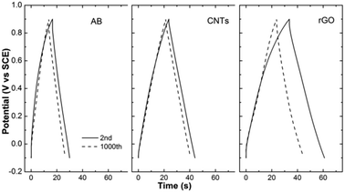 | ||
| Fig. 6 Galvanostatic charge/discharge curves of MnO2/C composites with 20 wt% of MnO2 at the current density of 3 A g−1. Solid lines and dash lines refer to 2nd and 1000th cycles, respectively. | ||
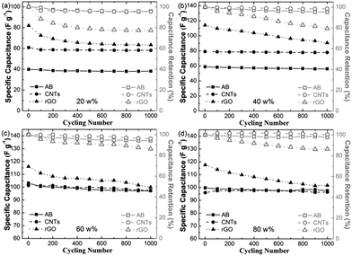
Fig. 7 shows the cyclability performance of the three types of MnO2/C composites at the current density of 3 A g−1. For 20 wt% of MnO2 (Fig. 7a), MnO2/CNTs and MnO2/AB were stable in 1000 cycles. Their specific capacitance could be maintained at ∼59 and ∼39 F g−1 during these cycles. The capacitance drop for them was about 4%. On the other hand, MnO2/rGO exhibited a remarkable capacitance drop of >10% within 100 cycles. The drop continued to ∼20% as the electrode was cycled for 300 cycles. Afterwards, the drop became slower. Fig. 7b shows the composites with 40 wt% of MnO2. MnO2/CNTs and MnO2/AB showed better stability during 1000 cycles. Their capacitance retention could reach nearly ∼98% and ∼95%. But MnO2/rGO showed ∼20% capacitance loss after 1000 cycles. As the mass loading of MnO2 increased to 60 and 80 wt%, MnO2/CNTs and MnO2/AB could achieve over 90% capacitance retention. In contrast, MnO2/rGO showed a bigger capacitance loss (∼15%). During the cycling measurement, it was found that the electrolyte near the electrode changed to brown color if MnO2/rGO was the working electrode. It is probably due to the better hydrophility of rGO, which facilitated the composite dissolution. As the mass ratio of rGO decreased, the dissolution of MnO2/rGO composites was not that significant as compared to those with high mass ratios of rGO![[thin space (1/6-em)]](https://www.rsc.org/images/entities/char_2009.gif) :
:![[thin space (1/6-em)]](https://www.rsc.org/images/entities/char_2009.gif) MnO2. As a result, the rGo composite with the low rGO loading could give slightly higher capacitance retention than those with the high rGO loading.
MnO2. As a result, the rGo composite with the low rGO loading could give slightly higher capacitance retention than those with the high rGO loading.
Conclusions
In summary, this article presents a comparison of three types of carbon supports in MnO2/C supercapacitors in terms of capacitive performance and cyclability using the three-electrode approach. All three types of composites and electrodes were made using the conventional method to keep them same in configuration. The capacitance contribution of carbon supports was subtracted from the overall capacitance. The comparison, in particular, was given to the contribution only from supported MnO2 among these three types of composites. It was found that rGO could enhance the capacitive performance of MnO2 at slow scan rates. However, MnO2/CNTs and MnO2/AB exhibited better capacitive performance at high rates as well as better stability. The information from this study would be also helpful to the investigation of the influence of carbon supports on supported nanoparticle electrocatalysts.Acknowledgements
This work is supported by Tier 1 grants of Singapore Ministry of Education (RGT8/13 & RG13/13), the COE Proposal Preparatory Grant 2013, and the Singapore National Research Foundation under its Campus for Research Excellence And Technological Enterprise (CREATE) programme.Notes and references
- B. Dunn, H. Kamath and J. M. Tarascon, Science, 2011, 334, 928–935 CrossRef CAS PubMed.
- W. F. Wei, X. W. Cui, W. X. Chen and D. G. Ivey, Chem. Soc. Rev., 2011, 40, 1697–1721 RSC.
- L. L. Zhang and X. S. Zhao, Chem. Soc. Rev., 2009, 38, 2520–2531 RSC.
- S. Liu, S. Sun and X.-Z. You, Nanoscale, 2014, 6, 2037–2045 RSC.
- A. Sumboja, C. Y. Foo, J. Yan, C. Yan, R. K. Gupta and P. S. Lee, J. Mater. Chem., 2012, 22, 23921–23928 RSC.
- Y. Cheng, H. Zhang, C. V. Varanasi and J. Liu, Energy Environ. Sci., 2013, 6, 3314–3321 CAS.
- X. Wang, C. Yan, A. Sumboja, J. Yan and P. S. Lee, Adv. Energy Mater., 2013, 4, 1301240 Search PubMed.
- Y. Cheng, S. Lu, H. Zhang, C. Varanasi and J. Liu, Nano Lett., 2012, 12, 4206–4211 CrossRef CAS PubMed.
- A. Sumboja, C. Foo, X. Wang and P. S. Lee, Adv. Mater., 2013, 25, 2809–2815 CrossRef CAS PubMed.
- S. W. Lee, J. H. Kim, S. Chen, P. T. Hammond and Y. Shao-Horn, ACS Nano, 2010, 4, 3889–3896 CrossRef CAS PubMed.
- S. W. Lee, B. M. Gallant, H. R. Byon, P. T. Hammond and Y. Shao-Horn, Energy Environ. Sci., 2011, 4, 1972–1985 CAS.
- A. S. Arico, P. Bruce, B. Scrosati, J. M. Tarascon and W. Van Schalkwijk, Nat. Mater., 2005, 4, 366–377 CrossRef CAS PubMed.
- Q. Qu, P. Zhang, B. Wang, Y. Chen, S. Tian, Y. Wu and R. Holze, J. Phys. Chem. C, 2009, 113, 14020 CAS.
- L. Mao, K. Zhang, H. S. On-Chan and J. Wu, J. Mater. Chem., 2012, 22, 1845 RSC.
- X. Wang, A. Yuan and Y. Wang, J. Power Sources, 2007, 172, 1007 CrossRef CAS PubMed.
- X. Lu, D. Zheng, T. Zhai, Z. Liu, Y. Huang, S. Xie and Y. Tong, Energy Environ. Sci., 2011, 4, 2915 CAS.
- L. Hu, W. Chen, X. Xie, N. Liu, Y. Yang, H. Wu, Y. Yao, M. Pasta, H. N. Alshareef and Y. Cui, ACS Nano, 2011, 5, 8904 CrossRef CAS PubMed.
- W. Xiao, D. Wang and X. W. Lou, J. Phys. Chem. C, 2009, 114, 1694 Search PubMed.
- Y. G. Guo, J. S. Hu and L. J. Wan, Adv. Mater., 2008, 20, 2878–2887 CrossRef CAS.
- Y. Cheng, H. Zhang, I. Cordova and J. Liu, J. Nano Energy Power Res., 2013, 2, 41–47 CrossRef PubMed.
- J. Yan, A. Sumboja, X. Wang, C. Fu, V. Kumar and P. S. Lee, Small DOI:10.1002/smll.201303553.
- C. Wei, L. Yu, C. Cui, J. Lin, C. Wei, N. Mathews, F. Huo, T. Sritharan and Z. Xu, Chem. Commun., 2014, 50, 7885–7888 RSC.
- J. Zhu, D. Yang, X. Rui, D. Sim, H. Yu, H. E. Hoster, P. M. Ajayan and Q. Yan, Small, 2013, 9, 3390–3397 CrossRef CAS PubMed.
- W. S. Hummers Jr and R. E. Offeman, J. Am. Chem. Soc., 1958, 80, 1339 CrossRef.
- C. Liu, Z. Yu, D. Neff, A. Zhamu and B. Z. Jang, Nano Lett., 2010, 10, 4863–4868 CrossRef CAS PubMed.
- Z. S. Wu, W. Ren, D. W. Wang, F. Li, B. Liu and H.-M. Cheng, ACS Nano, 2010, 4, 5835–5842 CrossRef CAS PubMed.
- M. Toupin, T. Brousse and D. Bélanger, Chem. Mater., 2004, 16, 3184–3190 CrossRef CAS.
- N. Mahmood, C. Zhang, H. Yin and Y. Hou, J. Mater. Chem. A, 2014, 2, 15–32 CAS.
- N. Mahmood, C. Zhang, F. Liu, J. Zhu and Y. Hou, ACS Nano, 2013, 7, 10307–10318 CrossRef CAS PubMed.
- C. Zhang, N. Mahmood, H. Yin, F. Liu and Y. Hou, Adv. Mater., 2013, 35, 4932–4937 CrossRef PubMed.
Footnote |
| † Electronic supplementary information (ESI) available: TEM images of MnO2 and MnO2/C composites, cyclic voltammograms and electrochemical impedance spectra of MnO2/C composites, the specific capacitance of MnO2/AB at the different scan rates and composition. See DOI: 10.1039/c4ra04914d |
| This journal is © The Royal Society of Chemistry 2014 |

