Low-voltage polymer monolayer transistors for high-gain unipolar and complementary logic inverters†
Miao
Cheng‡
ab,
Yanqin
Zhang‡
a,
Lei
Zheng‡
a,
Jianwei
Zhang
c,
Yifan
Xie
a,
Qingqing
Jin
a,
Yue
Tian
a,
Jinyao
Wang
a,
Hongmei
Xiao
d,
Chunmeng
Dou
a,
Zhenzhong
Yang
c,
Mengmeng
Li
 *ab,
Ling
Li
a and
Ming
Liu
a
aKey Lab of Fabrication Technologies for Integrated Circuits, Institute of Microelectronics, Chinese Academy of Sciences, Beijing 100029, China. E-mail: limengmeng@ime.ac.cn
bUniversity of Chinese Academy of Sciences, Beijing 100049, China
cKey Laboratory of Polar Materials and Devices (MOE) and Department of Electronics, East China Normal University, Shanghai 200241, China
dKey Laboratory of Science and Technology on Space Energy Conversion, Technical Institute of Physics and Chemistry, Chinese Academy of Sciences, Beijing 100190, China
First published on 25th May 2024
Abstract
Cutting-edge integrated circuits based on organic transistors, though promising, encounter a notable obstacle due to their tendency for high power consumption, thereby constraining their broader practical applications. This study demonstrates low-voltage polymer monolayer thin-film transistors (TFTs) and high-gain logic inverters, wherein the utilization of thin films of AlOx as gate dielectrics effectively enhances the gate controllability of TFTs. A photolithography-compatible method using a sacrificial layer is proposed to pattern the polymer monolayer, which significantly reduces off-state and gate leakage currents to 10−12 A and achieves a steep subthreshold swing of 86 mV dec−1. These device performances generate a maximum intrinsic gain of 104 V/V, enabling the development of zero-VGS-load logic inverters with voltage gains up to 251 V/V at a −3 V operation voltage (VDD). Additionally, hybrid complementary inverters by integrating with amorphous indium gallium zinc oxide (IGZO) exhibit ultra-high voltage gains of 841 V/V at a VDD of 5 V and 7436 V/V at a VDD of 30 V, potentially setting a new benchmark for logic inverters across various semiconductor systems. These results open new avenues for advancements in low-voltage organic and hybrid logics tailored for portable and wearable electronics.
Introduction
Semiconducting polymers have recently garnered extensive attention due to their unique advantages such as mechanical flexibility, low-temperature processability, tunable optoelectronic properties, lightweight nature and potential for mass production.1,2 Similar to their inorganic counterparts, polymer thin-film transistors (TFTs) represent one of the most important building blocks in plastic electronics, with immense potential in emerging fields such as the internet of things (IoT) and artificial intelligence (AI).3 To date, much effort has been devoted to the chemical design of semiconducting polymers, resulting in polymer TFTs with impressive field-effect mobilities of around 10 cm2 V−1 s−1 in both holes and electrons. For instance, diketopyrrolopyrrole-based polymers with well-defined microstructures exhibited a record-high hole mobility of 24 cm2 V−1 s−1.4 Isoindigo-based polymers were reported to demonstrate favorable electron-transporting properties, and an electron mobility of 9.7 cm2 V−1 s−1 was achieved.5While mobility is undeniably crucial for assessing transistor performance, an exclusive emphasis on this parameter neglects other equally vital performance metrics that are capable of bridging the gap between laboratory research and practical applications. The voltage range over which the transistor operates effectively is an important consideration for power consumption,6 but polymer TFTs often utilize a high operating voltage (the maximum value between a drain voltage and a gate voltage) ranging from ±20 V to ±100 V, because of the relatively low dielectric constant (ε) of the used gate dielectrics such as SiO2, Cytop, and poly(methyl methacrylate) (PMMA).7,8 It should be noted that the thermally grown SiO2 from silicon wafers typically offers an atomically flat surface, facilitating the crystallinity and molecular order of organic semiconductors.9,10 A thinner dielectric is in favor of lower operating voltage, but the tunnelling effect often leads to a high gate leakage current.11 Additionally, new types of organic, inorganic and hybrid dielectrics with high κ have been developed to enable low-voltage organic TFTs.6,12
A lower subthreshold swing (SS), defined as the gate voltage required to modulate the drain current by one order of magnitude when the TFT operates in the subthreshold region, is also crucial for enhancing energy efficiency and reducing power consumption in TFTs.13 Typically, the SS of polymer TFTs ranges from 0.5 V dec−1 to even a few V dec−1, which is one order of magnitude higher than the Boltzmann thermionic limit (60 mV dec−1 at room temperature). Another challenge to low power consumption in polymer TFTs is their high off-state drain current, primarily originating from the extra unpatterned semiconductor layer. In spite of recent progress in ink-jet printing14 for efficient patterning of organic semiconductors, photolithography-compatible strategies are preferred for achieving high-density polymer TFT arrays on a wafer scale.
In this study, low-voltage polymer TFTs are demonstrated with an operating voltage of only 3 V, wherein thin films of AlOx are utilized as gate dielectrics. It is found that thinner AlOx noticeably enhances gate controllability without affecting field-effect mobility. The polymer monolayer TFT exhibits identical transistor performance, with a significantly minimized off-state current and gate leakage current to around 10−12 A through the sacrificial layer method that is compatible with conventional photolithography techniques. Importantly, the SS of the polymer monolayer TFT is remarkably reduced from 1106 mV dec−1 to 86 mV dec−1 due to the much improved off-state drain current, compared to control devices with 300-nm-thick SiO2 as the dielectric. Consequently, the maximum intrinsic gain of such low-voltage polymer monolayer TFTs reaches 104 V/V in the subthreshold regime, and the resultant zero-VGS-load logic inverter exhibits a voltage gain of up to 251 V/V at an operation voltage (VDD) of −3 V. In addition, hybrid complementary inverters integrated using a p-type polymer monolayer and an n-type amorphous indium gallium zinc oxide (IGZO) offer superior voltage amplification capabilities, achieving voltage gains of 841 V/V at VDD = −5 V and 7436 V/V at VDD = −30 V, respectively, and these results rank among the record for organic and hybrid inverters.
Experimental
Materials and morphology characterization
Poly[(5,6-difluoro-2,1,3-benzothiadiazole-4,7-diyl)[3,3′′′-bis(2-decyltetradecyl)[2,2′:5′,2′′:5′′,2′′′-quaterthiophene]-5,5′′′-diyl]] (PffBT4T-2DT) was purchased from Nanjing Zhiyan Ltd and used without further purification. The molecular weight (Mn = 116.4 kg mol−1 and Mw/Mn = 1.87) was determined by gel permeation chromatography (GPC) at 150 °C with TCB as the eluent. The surface morphology of polymer thin films was recorded using an atomic force microscope (AFM, Bruker MultiMode-V). The sample for transmission electron microscopy (TEM) was prepared through an FEI Helios G4 UX dual beam focused ion beam/scanning electron microscope (FIB/SEM).Transistor fabrication
A bottom-gate bottom-contact architecture was utilized for the fabrication of polymer TFTs. (I) The gate electrode (Ti/Au 5 nm/30 nm) was patterned using conventional photolithography and electron beam evaporation (lift-off). (II) A 20 nm AlOx layer was deposited using ALD at 300 °C. (III) The source/drain (S/D) electrodes (Ti/Au 5 nm/30 nm) were patterned using photolithography and electron beam evaporation (lift-off), and then cleaned by oxygen plasma and then immersed into a 10 mM 2,3,4,5,6-pentafluorothiophenol (PFBT, Aldrich) solution in ethanol for 6 h to form a self-assembled monolayer. (IV) The contact pad of the gate electrode was etched for electrical measurements. (IV) A solution of PffBT4T-2DT in chloroform was prepared with a polymer concentration of 1 mg mL−1, and then spin-coated onto the prepatterned substrate at 1000 rpm for 30 s with a film thickness of around 15 nm. The corresponding polymer monolayer was dip-coated from 0.5 mg mL−1 chloroform solution with a pulling speed of 200 μm s−1. Afterwards, these ultrathin polymer films were annealed at 100 °C for 30 min to remove the residual solvent in a nitrogen glovebox.In order to pattern the organic semiconducting layer, the sacrificial layer of parylene/Cytop (300 nm/200 nm) was first deposited onto the organic semiconductors. Afterwards, the conventional photolithography and 10∼15 min of dry etching using oxygen plasma with a power of 100 W were performed to obtain the desired pattern. For the device with SiO2 as the dielectric, the highly doped silicon wafer with 300 nm thermally grown SiO2 was directly used. All electric measurements were carried out using a nitrogen glovebox.
Inverter fabrication
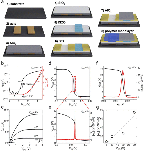
The deposition procedures of the gate electrode and AlOx dielectric were the same as those described in the transistor fabrication section. As shown in Fig. 5a, a sequential deposition strategy of 5-nm-thick SiO2 and 7-nm-thick a-IGZO thin films was conducted in the same chamber using magnetron sputtering. Such ultrathin SiO2 acted as the modification layer by preventing the dissociation of H2O and O2 into an active layer.15 After photolithography, the sample was etched using a dilute nitric acid solution to remove the unprotected IGZO. Then the photoresist was removed by acetone, and the sample was washed with acetone and isopropanol, respectively. Consequently, the patterned IGZO active layer was achieved. The bottom-gate top-contact configuration was used for the IGZO TFT, and the bottom-gate bottom-contact configuration was used for the polymer monolayer TFT. The deposition for the source and drain electrodes was described above. Before the deposition of the polymer monolayer, the patterned IGZO was passivated by AlOx grown by low-temperature ALD (200 °C). The channel length and width of the TFTs are summarized in Table S1 (ESI†).Results and discussion
Low-voltage polymer TFTs
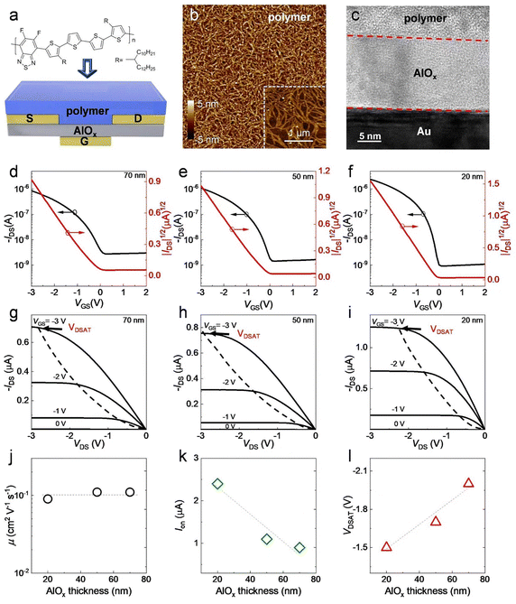
Thin films of AlOx are deposited as gate dielectrics by atomic layer deposition (ALD), which is compatible with traditional microelectronic processing, and a bottom-gate bottom-contact configuration is employed for transistor fabrication, as illustrated in Fig. 1a. The details of device fabrication are described in the Experimental section. A 15-nm-thick film is spin-coated from PffBT4T-2DT solution as the semiconducting layer, and nanofibrillar structures are observed (Fig. 1b). The transmission electron microscopy (TEM) image in Fig. 1c depicts the cross-section of the polymer TFT. The influence of the AlOx thickness on the gate controllability in polymer TFTs is first investigated. It is clear that polymer TFTs operate well in the saturation regime at a drain voltage (VDS) of −3 V across varying AlOx thickness from 70 nm to 20 nm, with an achievable on/off current ratio of around 103 (Fig. 1d–f). A near-ideal linear relationship between the square root of drain current (IDS) and the gate voltage (VGS) in the on-state ensures the accuracy of mobility extraction from transfer characteristics (red lines in Fig. 1d and e). The resultant saturated mobility is around 0.1 cm2 V−1 s−1 and remains nearly independent of the AlOx thickness (Fig. 1j). It is worth noting that the on-state current (Ion) is significantly enhanced with decreasing dielectric thickness, indicating the improvement of the gate controllability (Fig. 1k). This improvement is further validated by the output characteristics (Fig. 1g–i). As summarized in Fig. 1l, IDS attains saturation at a smaller IDS in the case of a thinner dielectric, corresponding to a smaller saturation drain voltage (VDSAT). As a result, 20-nm-thick AlOx is selected as the gate dielectric for further investigation.Patterning of the organic semiconducting layer
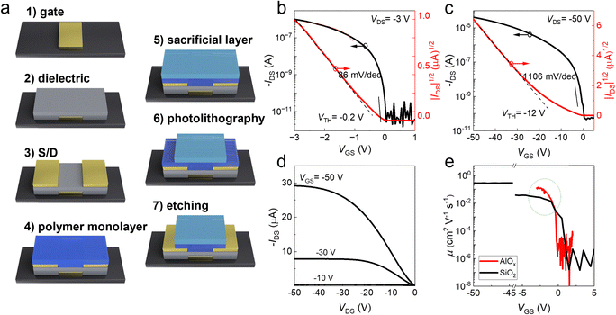
Scaling down the PffBT4T-2DT thin film to a single molecular layer (monolayer) has a negligible impact on transistor performance.16,17 However, as evident in Fig. 1d–f, the absence of patterning the semiconducting layer leads to a relatively high off-state drain current and gate leakage current, both of which are detrimental to static power consumption. Therefore, a patterning strategy using the sacrificial layer is proposed for the polymer monolayer TFTs, as shown in Fig. 2a. Compared with the spin-coated thin film, the dip-coated polymer monolayer shows larger nanofibers with a thickness of approximately 2.4 nm,16,18 indicating a higher degree of molecular order (inset of Fig. 2b). Despite the previous reports,19,20 we find that the direct contact between parylene and PffBT4T-2DT leads to a severe doping effect, while the Cytop surface suffers from a low yield of the photolithography process. Hence, a double layer of Cytop/parylene is designed: (i)Cytop acts as a robust encapsulation layer for the semiconducting polymer; (ii) additional encapsulation using parylene ensures compatibility with a conventional photolithography technique and subsequent dry-etching processes. Fig. 2b displays the transfer characteristics of the patterned polymer monolayer TFT, with a resulting saturated mobility of 0.1 cm2 V−1 s−1. A significant benefit of patterning is the three-order-of magnitude reduction in the off-state drain current to around 10−12 A, accompanied by an increased on/off current ratio of 106. Furthermore, the resultant gate leakage current is also sufficiently minimized to 10−11∼10−12 A after patterning the polymer monolayer (Fig. 2b and Fig. S1, ESI†). Additionally, the patterning process contributes to a significant improvement in the SS, achieving a minimum value of 86 mV dec−1, lower than that reported in the literature.21,22
The polymer monolayer TFT with 300 nm SiO2 as the dielectric layer is fabricated for comparison. As shown in Fig. 2c and d, the typical linear/saturation behavior of IDS is observed, but high operating voltages of −50 V including VDS and VGS are necessary. The corresponding threshold voltage (VTH) and SS are −12 V and 1106 mV dec−1, respectively. In sharp contrast, the utilization of 20 nm AlOx remarkably improves the device performance of polymer monolayer TFTs due to much improved gate controllability, as summarized in Table 1. The interface between the polymer monolayer and the gate dielectric is also studied. The SS can be expressed as follows:12
| SS = kBT × ln(10)(1 + q2Dt/Ci)/q | (1) |
Unipolar logic inverters
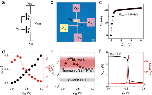
In display driver circuits, inverters serve as the foundational cornerstone, functioning not only as the core element but also as the fundamental building block upon which the entire circuit architecture is constructed.23 On the basis of these low-voltage polymer monolayer TFTs, the logic inverter is integrated with a zero-VGS-load architecture, where a normal structure TFT acts as a driver (M1) and a zero-VGS TFT with a gate source electrode interconnected as a load (M2), as shown in Fig. 3a and b. The operating state of the driver TFT is made to switch between the on state and off state by varying the input voltage in order to observe a voltage jump at the output. Fig. 3c shows the output characteristics and the method of extracting output resistance (ro) at a VGS of 0 V of the load M2 transistor, with a resultant load resistance of 1.36 GΩ.Before the inverter measurement, an intrinsic gain Ai of polymer monolayer TFTs needs to be clarified, which can be estimated by the following equation:
| Ai = gmro | (2) |
Fig. 3f exhibits the input–output characteristic of the polymer monolayer inverter with a zero-VGS-load architecture, where VDD= −3 V is applied. A steep level transition of input voltages (VIN) is observed, suggesting clear voltage amplification with a voltage gain (Av) up to 251 V/V at the peak. When VDD is decreased to −2 V, the corresponding Av is slightly reduced but can still reach 181 V/V (Fig. S2, ESI†), comparable to the previously reported record based on high-crystalline small molecules.12
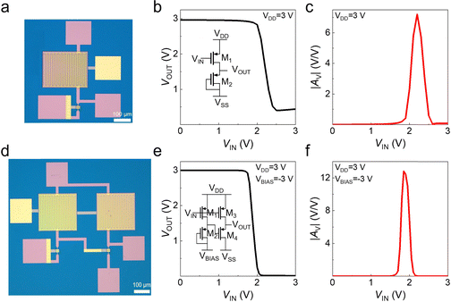
Unipolar circuits only need to process one kind of semiconductor layer, simplifying the fabrication procedure of integrated circuits.2 Besides the zero-VGS-load architecture, the diode-load and pseudo-E structures are also popular with sufficient simplicity. In particular, the former consists of two TFTs. Despite the requirement of more TFTs, the latter allows adjustable gain and voltage jump points, effectively integrating the functions of a bias circuit and an amplification circuit. Fig. 4 depicts the input–output characteristics of polymer monolayer inverters with these two circuit designs, where a low VDD of 3 V is applied. In both cases, clear inverting behaviors of the input signal phase by 180° are observed (Fig. 4b and e). The resultant voltage gain is 7 V/V for a diode-load inverter and 13 V/V for a pseudo-E inverter, and further decreased with decreasing channel width of the driver transistor and bias voltages (Fig. S3 and S4, ESI†). This inverter performance could be effectively improved using a dual-gate technology to precisely tune the threshold voltage.24
Complementary logic inverters
In comparison to unipolar circuits, complementary inverters consisting of both p-type and n-type transistors are capable of enhancing the capability of pulling up and pulling down of output voltage, thereby improving the noise margin. Furthermore, in complementary inverters, one transistor is consistently in the off state, characterized by the low off-state drain current, resulting in notably reduced power consumption.2 Due to the lack of high-mobility n-type conjugated polymers,25 an amorphous indium–gallium–zinc–oxide (IGZO) TFT is utilized, offering distinct advantages such as high electron mobility and minimal off-state drain current. This IGZO TFT is seamlessly integrated with a polymer monolayer TFT, as depicted in Fig. 5a. To optimize performance, an ultra-thin SiO2 layer is interposed between the IGZO layer and the AlOx dielectric for interfacial modification. Meanwhile, the IGZO TFT undergoes passivation using low-temperature AlOx prior to the deposition of the polymer monolayer.15Fig. 5b and c exhibits the transfer and output characteristics of the integrated IGZO TFT within the complementary inverter, and the resultant gate leakage current is generally below 10−10 A (Fig. S5, ESI†). The linear electron mobility measures approximately 13.6 cm2 V−1 s−1, with an SS of 113 mV dec−1, an on/off current ratio of 107 and a threshold voltage of 1.7 V. Compared to the pristine polymer monolayer TFTs, the resulting complementary inverter operates with a slightly higher VDD of 5 V, achieving an ultra-high voltage gain of up to 841 V/V (Fig. 5d and e). Such voltage amplification is in excellent agreement with the theoretical simulation (823 V/V) from small signal analysis,26 which is mainly attributed to the large output resistance of both TFTs. It is worth noting that this inverter performance surpasses that of the unipolar zero-VGS-load polymer monolayer inverter by a factor of three (Fig. 3f), and exceeds that of all-polymer monolayer complementary inverters in our previous study by a factor of seven,6 as outlined in Table 2. Notably, increasing VDD remarkably enhances the voltage gain of this hybrid complementary inverter, reaching a maximum value of 7436 V/V at a VDD of 30 V (Fig. 5f and g and Fig. S6, ESI†).
The remarkable voltage amplification achieved in our study is benchmarked against various semiconductor systems, including pristine semiconducting polymers16,25,27–37 (both unipolar and complementary configurations), p-type oxide semiconductors,38–42 p-type organic semiconductors43–52 (such as polymers and carbon nanotubes) and n-type IGZO (complementary). At VDD < 10 V, the voltage gains reported in the literature typically fall below 50 V/V, representing a roughly 4-fold difference compared to our hybrid inverters composed of the polymer monolayer and IGZO. As VDD increases to 10 V or higher, the reported maximum voltage gain ranges between 100 V/V and 400 V/V, whereas our devices demonstrate voltage amplification reaching the order of 103 V/V, potentially setting a new benchmark for logic inverters (Fig. 6).
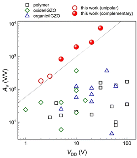 | ||
| Fig. 6 Benchmarking of polymer inverters that have been reported so far. VDD is the absolute value of the operation voltage. Data are from ref. 15, 24 and 27–37 for polymer inverters, from ref. 38–42 for oxide/IGZO inverters and ref. 43–52 for organic/IGZO hybrid inverters. “Organic” materials in this figure include semiconducting polymers and carbon nanotubes. | ||
Conclusions
In conclusion, a thin film of AlOx is grown by the ALD method and acts as the gate dielectric for polymer monolayer TFTs, which effectively reduces the operating voltage to 3 V with improved Ion and VDSAT. To pattern the polymer monolayer, a photolithography-compatible strategy utilizing a sacrificial layer is developed, significantly reducing the off-state current and gate leakage current to approximately 10−12 A. Consequently, the resultant polymer monolayer TFTs exhibit a steep SS of 86 mV dec−1 and maximum intrinsic gains of up to 104 V/V. These exceptional transistor performances have facilitated the development of high-gain logic inverters, achieving a voltage gain of 251 V/V for the zero-VGS-load configuration at a VDD of −3 V. On the other hand, complementary inverters are also realized by integrating p-type polymer monolayer TFTs and n-type IGZO TFTs, resulting in ultra-high voltage gains of 841 V/V at a VDD of 5 V and 7436 V/V at a VDD of 30 V, respectively. This study thus paves a new way for further improvements in power consumption and large-area fabrication of organic electronic devices.Author contributions
M. L. conceived the idea and supervised the study; M. C. and L. Z. fabricated TFTs and conducted the electrical measurement; Y. Z. fabricated inverters and conducted the electrical measurement; J. Z. and Z. Y. measured TEM; M. L. prepared the manuscript with support from all co-authors; all authors discussed the results and contributed to this work.Conflicts of interest
There are no conflicts to declare.Acknowledgements
This work was supported by the National Key R&D Program of China under Grant 2019YFA0706100 and the National Natural Science Foundation of China under Grant 62074163.References
- L. Ding, Z.-D. Yu, X.-Y. Wang, Z.-F. Yao, Y. Lu, C.-Y. Yang, J.-Y. Wang and J. Pei, Chem. Rev., 2023, 123, 7421–7497 CrossRef CAS PubMed.
- Y. Xie, C. Ding, Q. Jin, L. Zheng, Y. Xu, H. Xiao, M. Cheng, Y. Zhang, G. Yang, M. Li, L. Li and M. Liu, SmartMat, 2024, e1261 CrossRef.
- H. Wang, Y. Chen, Z. Ni and P. Samorì, Adv. Mater., 2022, 34, 2205945 CrossRef CAS PubMed.
- Y. Yao, H. Dong, F. Liu, T. P. Russell and W. Hu, Adv. Mater., 2017, 29, 1701251 CrossRef PubMed.
- J. Yang, Z. Zhao, H. Geng, C. Cheng, J. Chen, Y. Sun, L. Shi, Y. Yi, Z. Shuai, Y. Guo, S. Wang and Y. Liu, Adv. Mater., 2017, 29, 1702115 CrossRef PubMed.
- R. P. Ortiz, A. Facchetti and T. J. Marks, Chem. Rev., 2010, 110, 205–239 CrossRef CAS PubMed.
- J. B. Ko, H. I. Yeom and S.-H. K. Park, IEEE Electron Device Lett., 2016, 37, 39–42 CAS.
- M. Li, A. H. Balawi, P. J. Leenaers, L. Ning, G. H. L. Heintges, T. Marszalek, W. Pisula, M. M. Wienk, S. C. J. Meskers, Y. Yi, F. Laquai and R. A. J. Janssen, Nat. Commun., 2019, 10, 2867 CrossRef PubMed.
- M. Li, C. An, T. Marszalek, M. Baumgarten, K. Müllen and W. Pisula, Adv. Mater., 2016, 28, 2245–2252 CrossRef CAS PubMed.
- M. Li, F. Hinkel, K. Müllen and W. Pisula, Nanoscale, 2016, 8, 9211–9216 RSC.
- G. Xu, W. Wang, L. Wang, Z. Zong, C. Lu, L. Wang, W. Banerjee, Z. Ji, H. Wang, L. Li and M. Liu, IEEE Trans. Electron Devices, 2015, 62, 4225–4230 CAS.
- C. Jiang, H. W. Choi, X. Cheng, H. Ma, D. Hasko and A. Nathan, Science, 2019, 363, 719–723 CrossRef CAS PubMed.
- Y. Zhai, Z. Feng, Y. Zhou and S.-T. Han, Mater. Horiz., 2021, 8, 1601–1617 RSC.
- J. Kwon, Y. Takeda, R. Shiwaku, S. Tokito, K. Cho and S. Jung, Nat. Commun., 2019, 10, 54 CrossRef CAS PubMed.
- Y. Zhang, Y. Xie, S. Zhang, L. Wang, M. Li and L. Li, in 2023 IEEE International Conference on Integrated Circuits, Technologies and Applications (ICTA), 2023, pp. 37–38 Search PubMed.
- M. Li, D. K. Mangalore, J. Zhao, J. H. Carpenter, H. Yan, H. Ade, H. Yan, K. Müllen, P. W. M. Blom, W. Pisula, D. M. de Leeuw and K. Asadi, Nat. Commun., 2018, 9, 451 CrossRef PubMed.
- J. Liu, W. Hu and L. Jiang, Sci. Bull., 2023, 68, 1474–1477 CrossRef CAS PubMed.
- M. Li, H. Bin, X. Jiao, M. M. Wienk, H. Yan and R. A. J. Janssen, Angew. Chem., 2020, 132, 856–862 CrossRef.
- W. Tang, J. Zhao, L. Feng, P. Yu, W. Zhang and X. Guo, IEEE Electron Device Lett., 2015, 36, 59–61 CAS.
- I. Kymissis, C. D. Dimitrakopoulos and S. Purushothaman, J. Vac. Sci. Technol., B, 2002, 20, 956–959 CrossRef CAS.
- L. Herlogsson, X. Crispin, N. D. Robinson, M. Sandberg, O.-J. Hagel, G. Gustafsson and M. Berggren, Adv. Mater., 2007, 19, 97–101 CrossRef CAS.
- J. H. Cho, J. Lee, Y. Xia, B. Kim, Y. He, M. J. Renn, T. P. Lodge and C. Daniel Frisbie, Nature Mater., 2008, 7, 900–906 CrossRef CAS PubMed.
- S. Tokito, Y. Takeda, K. Fukuda and D. Kumaki, Dig. Tech. Pap. - Soc. Inf. Disp. Int. Symp., 2014, 45, 180–182 CrossRef CAS.
- K. Myny, M. J. Beenhakkers, N. A. J. M. van Aerle, G. H. Gelinck, J. Genoe, W. Dehaene and P. Heremans, IEEE J. Solid-State Circuits, 2011, 46, 1223–1230 Search PubMed.
- Y. Guo, M. Yang, J. Deng, C. Ding, C. Duan, M. Li, L. Li and M. Liu, Adv. Electron. Mater., 2023, 9, 2201307 CrossRef CAS.
- B. Kheradmand-Boroujeni, G. C. Schmidt, D. Höft, K. Haase, M. Bellmann, K. Ishida, R. Shabanpour, T. Meister, C. Carta, A. C. Hübler and F. Ellinger, Org. Electron., 2016, 34, 267–275 CrossRef CAS.
- Z. Yi, Y. Jiang, L. Xu, C. Zhong, J. Yang, Q. Wang, J. Xiao, X. Liao, S. Wang, Y. Guo, W. Hu and Y. Liu, Adv. Mater., 2018, 30, 1801951 CrossRef PubMed.
- T. Leydecker, M. A. Squillaci, F. Liscio, E. Orgiu and P. Samorì, Chem. Mater., 2019, 31, 6491–6498 CrossRef CAS.
- J. Fan, J. D. Yuen, M. Wang, J. Seifter, J.-H. Seo, A. R. Mohebbi, D. Zakhidov, A. Heeger and F. Wudl, Adv. Mater., 2012, 24, 2186–2190 CrossRef CAS PubMed.
- J. Yang, Q. Liu, M. Hu, S. Ding, Yu Liu, Y. Wang, D. Liu, H. Gao, W. Hu and H. Dong, Sci. China Chem., 2021, 64, 1410–1416 CrossRef CAS.
- F. S. Kim, X. Guo, M. D. Watson and S. A. Jenekhe, Adv. Mater., 2010, 22, 478–482 CrossRef CAS PubMed.
- H. W. Park, K.-Y. Choi, J. Shin, B. Kang, H. Hwang, S. Choi, A. Song, J. Kim, H. Kweon, S. Kim, K.-B. Chung, B. Kim, K. Cho, S.-K. Kwon, Y.-H. Kim, M. S. Kang, H. Lee and D. H. Kim, Adv. Mater., 2019, 31, 1901400 CrossRef PubMed.
- D. Khim, W.-H. Lee, K.-J. Baeg, D.-Y. Kim, I.-N. Kang and Y.-Y. Noh, J. Mater. Chem., 2012, 22, 12774–12783 RSC.
- E. Stucchi, A. D. Scaccabarozzi, F. A. Viola and M. Caironi, J. Mater. Chem. C, 2020, 8, 15331–15338 RSC.
- A. Luzio, F. G. Ferré, F. D. Fonzo and M. Caironi, Adv. Funct. Mater., 2014, 24, 1790–1798 CrossRef CAS.
- S. P. Senanayak, V. K. Sangwan, J. J. McMorrow, K. Everaerts, Z. Chen, A. Facchetti, M. C. Hersam, T. J. Marks and K. S. Narayan, Adv. Electron. Mater., 2015, 1, 1500226 CrossRef.
- K.-M. Huang, H.-C. Lin, K. Kawashima, I. Osaka, H.-W. Zan, H.-F. Meng and K. Takimiya, Org. Electron., 2017, 50, 325–330 CrossRef CAS.
- M. Wang, L. Liang, H. Luo, S. Zhang, H. Zhang, K. Javaid and H. Cao, IEEE Electron Device Lett., 2016, 37, 422–425 CAS.
- Y. Li, J. Yang, Y. Wang, P. Ma, Y. Yuan, J. Zhang, Z. Lin, L. Zhou, Q. Xin and A. Song, IEEE Electron Device Lett., 2018, 39, 208–211 CAS.
- L.-J. Chi, M.-J. Yu, Y.-H. Chang and T.-H. Hou, IEEE Electron Device Lett., 2016, 37, 441–444 CAS.
- H.-J. Joo, M.-G. Shin, S.-H. Kwon, H.-Y. Jeong, H.-S. Jeong, D.-H. Kim, X. Jin, S.-H. Song and H.-I. Kwon, IEEE Electron Device Lett., 2019, 40, 1642–1645 CAS.
- S.-M. Hsu, D.-Y. Su, F.-Y. Tsai, J.-Z. Chen and I.-C. Cheng, IEEE Trans. Electron Devices, 2021, 68, 1070–1074 CAS.
- H. Chen, Y. Cao, J. Zhang and C. Zhou, Nat. Commun., 2014, 5, 4097 CrossRef CAS PubMed.
- H. Cheong, K. Kuribara, S. Ogura, N. Fukuda, M. Yoshida, H. Ushijima and S. Uemura, Jpn. J. Appl. Phys., 2016, 55, 04EL04 CrossRef.
- J. Yoon, H. Jung, J. T. Jang, J. Lee, Y. Lee, M. Lim, D. M. Kim, D. H. Kim and S.-J. Choi, J. Alloys Compd., 2018, 762, 456–462 CrossRef CAS.
- M. Li, J. Wang, X. Cai, F. Liu, X. Li, L. Wang, L. Liao and C. Jiang, Adv. Electron. Mater., 2018, 4, 1800211 CrossRef.
- K.-T. Kim, S.-H. Kang, J. Kim, J. S. Heo, Y.-H. Kim and S. K. Park, Adv. Electron. Mater., 2020, 6, 1900845 CrossRef CAS.
- Y. Lee, J. Yoon, J. T. Jang, B. Choi, H.-J. Kim, G.-H. Park, D. M. Kim, D. H. Kim, M.-H. Kang and S.-J. Choi, AIP Adv., 2020, 10, 025131 CrossRef CAS.
- Z. Peng, F. Liu, H. Sun, Y. Wang, J. Wang and C. Jiang, IEEE J. Electron Devices Soc., 2021, 9, 933–938 CAS.
- K. Nomura, J. Inf. Disp., 2021, 22, 211–229 CrossRef CAS.
- E. Bestelink, P. Sihapitak, U. Zschieschang, L. Askew, J. M. Shannon, J. Paolo Bermundo, Y. Uraoka, H. Klauk and R. A. Sporea, J. Mater. Chem. C, 2023, 11, 11688–11696 RSC.
- Y. Han, S. Kim, C.-H. Kim and H. Yoo, IEEE Trans. Electron Devices, 2023, 70, 1710–1714 CAS.
Footnotes |
| † Electronic supplementary information (ESI) available. See DOI: https://doi.org/10.1039/d4tc01715c |
| ‡ Contributed equally to this work. |
| This journal is © The Royal Society of Chemistry 2024 |

