
Ultraviolet photodissociation circular dichroism spectroscopy of protonated L-phenylalanyl-L-alanine in a cryogenic ion trap†
Il Tae
Yoo‡
a,
Han Jun
Eun‡
a,
Ahreum
Min
b,
Chang Wook
Jeon
a,
Jinho
Jeong
a,
Jiyoung
Heo
 c and
Nam Joon
Kim
*a
c and
Nam Joon
Kim
*a
aDepartment of Chemistry, Chungbuk National University, Chungbuk 28644, Korea. E-mail: namjkim@chungbuk.ac.kr
bDepartment of Chemistry (BK21 +) and Research Institute of Natural Science, Gyeongsang National University, Jinju 52828, Korea
cDepartment of Green Chemical Engineering, Sangmyung University, Chungnam 31066, Korea
First published on 15th October 2021
Abstract
We obtained ultraviolet photodissociation (UVPD) circular dichroism (CD) spectra of protonated L-phenylalanyl-L-alanine (L-H+PheAla) near the origin band of the S0–S1 transition using cryogenic ion spectroscopy. Infrared (IR) ion-dip, IR-UV hole burning (HB) and UV-UV HB spectra showed that L-H+PheAla existed as two different conformers in a cryogenic ion trap, and they had nearly identical peptide backbones but different conformations in the Phe side chain. The UVPD CD spectra revealed that the two conformers had opposite CD signs and significantly different CD magnitudes from each other. These results demonstrate that the CD value of L-H+PheAla near the origin band is strongly influenced by the conformation of the Phe side chain.
Introduction
Circular dichroism (CD) spectra exhibit differences in the absorption for left- and right-handed circularly polarized light (LCP and RCP, respectively). The CD spectra are sensitive to both the handedness and conformations of chiral molecules and thus have been extensively investigated to obtain information on the structures and structural changes in various reactions.1–3 In particular, it is well-known that the CD spectra of proteins in the near-UV region reflect the conformations of aromatic amino acids, which are closely connected with the tertiary structures of proteins.4However, the relationships between the conformations of aromatic amino acids and the CD spectra of proteins in the near-UV region have not been clearly defined due to the following challenges.5,6 First, aromatic amino acids in a protein usually exist in many different conformations in solution. Second, the CD spectra exhibit only the averaged CD features of all different conformations in solution, which are even weighted not only by the relative populations of different conformers but also by their relative CD sizes. Thus, conformers with a greater CD value rather than those with a greater population can dominate the CD spectral features. These challenges, however, can be overcome by measuring conformation-selective CD spectra by applying CD spectroscopic techniques to cold, isolated molecules in the gas phase.7
Since the first CD measurement for jet-cooled 3-methylcyclopentanone,8 the CD of gas-phase chiral molecules has been extensively investigated using resonance enhanced multiphoton ionization spectroscopy.9,10 Photoelectron CD spectroscopy (PECD) has also been used as an alternative tool to probe the chiroptical properties of molecules and clusters in the gas phase.11,12 As one of the pioneers, Powis reported the first theoretical predictions on the magnitudes of PECD for randomly oriented chiral molecules, which were later confirmed by measuring 2D projection images of the photoelectron angular distributions of jet-cooled camphor.13–15 PECD has been developed further to differentiate enantiomers in multicomponent mixtures.16 Cavity ring-down polarimetry was also used to measure the circular birefringence and CD of gaseous chiral molecules.17 The matrix isolation technique has been utilized to determine the conformational distribution of chiral molecules in cryogenic rare gas matrices by measuring the vibrational CD spectra.18,19
Recently, CD spectroscopy has been applied to molecular ions produced by electrospray ionization (ESI).20–22 ESI is one of the most powerful methods for producing large molecular ions in the gas phase.23 Hence, the combination of CD spectroscopy with ESI mass spectrometry has great potential as a tool for investigating large biomolecules such as proteins and DNA in the gas phase. Gabelica and coworkers21 obtained the electronic CD spectra of DNA helices stored in an ion trap at room temperature. The CD spectra of protonated L-phenylalanine (L-H+Phe) were also measured using cryogenic ion spectroscopy.20 In cryogenic ion spectroscopy, various laser spectroscopic techniques are employed to interrogate the structures and properties of molecular ions stored in a cryogenic ion trap.24–30 By applying a CD spectroscopic technique in conjunction with other laser spectroscopic techniques to the ions in the cryogenic ion trap, we obtained the conformation-specific CD spectra of L-H+Phe ions.20
Here, we investigate protonated L-phenylalanyl-L-alanine (L-H+PheAla) ions using ultraviolet photodissociation (UVPD) CD spectroscopy near the origin band of the S0–S1 transition. The structures of Ac-Phe-OMe, Ac-Phe-NHMe, and Ac-Phe-Ala-NH2 were previously investigated using resonant 2-photon ionization (R2PI) and infrared (IR)-UV double resonance spectroscopy.31–34 H+PheAla ions produced by ESI were also investigated using IR multiple-photon dissociation spectroscopy.35 It was reported that a single conformation of H+PheAla dominated the room temperature equilibrium population. In this work, we identified two different conformers of L-H+PheAla present in a cryogenic ion trap using UVPD, IR ion-dip, IR-UV hole burning (HB), and UV-UV HB spectroscopy combined with quantum theoretical calculations. The two conformers have nearly identical peptide backbone structures but different conformations in the Phe side chain. We investigate how the different conformations of the Phe side chain are reflected in the CD spectra of L-H+PheAla in the near UV region.
Experimental
Experimental details
The experimental setup was previously described in detail, and only a brief description is given below.20 Powder samples of L-PheAla and D-PheAla were purchased from Koma Biotech (South Korea) and used without further purification. The powder sample was dissolved in methanol at a concentration of 70 μM. The solution was electrosprayed into ion droplets, which were passed through a glass capillary heated to 140 °C by hot dry gas (3 L min−1), generating L-H+PheAla or D-H+PheAla ions in the gas phase. These ions went through a skimmer and a hexapole guide, and were mass-selected in a quadrupole mass filter. Passing through an octupole guide, the ions were introduced into a quadrupole ion trap (QIT), which was cooled down to ∼10 K by a closed-cycle helium refrigerator. Before the introduction of ions, helium gas was injected into the QIT through a pulsed nozzle for collisional cooling. The ions were stored in the QIT for 44 ms and irradiated by a UV laser pulse for photodissociation. All the ions in the QIT were extracted to a reflectron time-of-flight (reTOF) mass spectrometer by applying positive and negative DC pulses on the entrance and exit endcaps of the QIT, respectively. The UVPD spectra were obtained by monitoring photofragment signals as a function of the UV wavelength. The frequency-doubled output of a dye laser (1–2 mJ per pulse at 10 Hz) pumped by an Nd:YAG laser was used.For IR ion-dip spectroscopy, an IR pump laser was irradiated 220 ns earlier than a UV probe laser. The UV probe laser at 20 Hz was fixed to a vibronic band of a certain isomer, and the IR pump laser at 10 Hz was tuned over the wavenumber range of 3100–3700 cm−1. When the IR pump wavelength was resonant with a vibrational transition of the isomer, the ground-state population of the isomer was depleted, which decreased the fragment signals generated by the UV probe pulse. IR ion-dip spectra were obtained by subtracting the IR-off signals from IR-on signals as a function of the IR wavelength. IR laser pulses were generated using a tunable IR laser (LaserVision, OPO/OPA) pumped by an Nd:YAG laser at 10 Hz.
For IR-UV HB spectroscopy, an IR pump laser was fixed to a vibrational band of a certain isomer and a UV probe laser was scanned over the wavelength range. The IR pump pulse, which was irradiated 220 ns earlier than the UV probe, depleted the ground-state population of the isomer. Hence, when the UV probe laser was resonant with a vibronic transition of the same isomer, the fragment signals generated by the UV probe pulse with IR-on would be lower than those with IR-off. IR-UV HB spectra were obtained by subtracting the fragment signals generated with IR-off from those with IR-on.
UV-UV HB and UVPD CD spectra were obtained using a multiple laser-shots (MLS) technique.20 In the MLS technique, the ions in the QIT were not extracted to the reTOF mass spectrometer following irradiation with a UV laser pulse, and a second cycle began by injecting helium gas and new parent ions into the QIT. All the ions in the QIT were cooled again at ∼10 K and irradiated by a second UV pulse. This process was repeated until the irradiation of the UV probe pulse during the nth cycle. Then, all the ions inside the QIT were extracted to the reTOF mass spectrometer for detection.
For UV-UV HB spectroscopy, a UV probe laser was fixed to a vibronic band of a specific isomer, and a UV pump laser was scanned over the entire wavelength range. Three pulses of the UV pump laser were irradiated during the first three cycles of the MLS technique, and a single UV probe pulse was irradiated during the 4th cycle. The fragment ions produced by the UV pump pulses were ejected out of the QIT in each cycle by applying a “tickle RF pulse” to the entrance endcap of QIT for 1 ms.36 Only the fragment ions generated by the UV probe pulse during the 4th cycle were extracted to the reTOF mass spectrometer. When the UV pump pulse was resonant with a vibronic transition of the specific isomer, the ground-state population of the isomer was depleted by photofragmentation, which decreased the fragment signals generated by the UV probe pulse during the 4th cycle. UV-UV HB spectra were obtained by monitoring the differences between the fragment signals generated by the UV probe pulse with and without irradiation of the UV pump pulses.
UVPD CD spectra were obtained by subtracting fragmentation yields by RCP pulses from those by LCP pulses using the 4 cycles of the MLS technique. The fragmentation yield was given by F/(F + P), where F and P represent the fragment and parent signals, respectively, measured after irradiation of LCP or RCP pulses.
LCP and RCP pulses were generated by passing linearly polarized laser pulses through a polarizer and then a photoelastic modulator (PEM).37 The retardation value of PEM oscillates from −λ/4 to +λ/4 at a frequency of 50 kHz. LCP and RCP pulses were generated by passing linearly polarized laser pulses through the PEM when the retardation value reached −λ/4 and +λ/4, respectively. To synchronize the PEM oscillation with the laser firing, the reference pulses of PEM were downcounted to 10 Hz using a frequency divider. The 10 Hz pulses were fed into a digital delay generator (DG), which generated 10 Hz pulses delayed by either δt1 or δt2 from the 10 Hz pulses of the frequency divider. The 10 Hz outputs of DG were used to trigger the firing of the UV laser. δt1 and δt2 were adjusted in such a way that the laser pulses fired by the 10 Hz output of DG passed through the PEM when the retardation value reached −λ/4 and +λ/4, respectively. LCP and RCP pulses were alternated by changing the time delay between δt1 and δt2 using a computer.
Computational details
The initial structures of L-H+PheAla were searched using CONFLEX software with the Merck Molecular Force Field MMFF94S.38 We found 51 conformers within the energy range of 10 kcal mol−1 and fully optimized their geometries using density functional theory (DFT) at the CAM-B3LYP/6-311++G (d,p) level. The vibrational frequencies of the optimized geometries were calculated at the same level of theory. The rotatory strengths R, which theoretically represent the experimental CD values, were predicted using time-dependent DFT (TDDFT) calculations at the CAM-B3LYP/6-311++G (d,p) level. All of the calculations were performed using Gaussian 09 software.39Results
Fig. 1a shows the UVPD spectrum of L-H+PheAla near the origin band of the S0–S1 transition, which was obtained by monitoring the sum of fragment signals at m/z 145 and 149.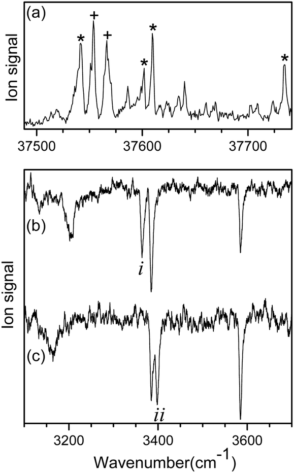 | ||
| Fig. 1 (a) UVPD spectrum of L-H+PheAla near the origin band of the S0–S1 transition obtained by monitoring the sum of fragment signals at m/z 145 and 149. IR ion-dip spectra obtained by fixing a UV probe laser at the vibronic bands labeled as (b) * and (c) +, respectively. | ||
The mass spectrum of L-H+PheAla obtained by irradiating a UV laser pulse at 37 542 cm−1 is shown in Fig. S1 (ESI†). Fig. 1b and c are the IR ion-dip spectra of L-H+PheAla obtained by fixing a UV probe laser at the bands labeled * and + in Fig. 1a, respectively. The IR ion-dip spectra exhibited spectral features distinct from each other, indicating that L-H+PheAla ions exist as at least two different conformers in the cryogenic ion trap. The conformers in Fig. 1b and c were labeled as I and II, respectively.
Fig. 2 shows the IR-UV HB spectra obtained by fixing an IR pump laser to the vibrational band i or ii in the IR ion-dip spectra (Fig. 1). The IR pump laser at bands i and ii depletes the ground-state populations of conformers I and II, respectively, giving rise to dip signals in the IR-UV HB spectra. Thus, the dip signals in Fig. 2a and b are regarded as the vibronic bands of conformers I and II, respectively. Nearly all the vibronic bands in the UVPD spectrum (Fig. 2c) appeared as dip signals in either of the two IR-UV HB spectra, which further supported the presence of two conformers of L-H+PheAla in the ion trap.
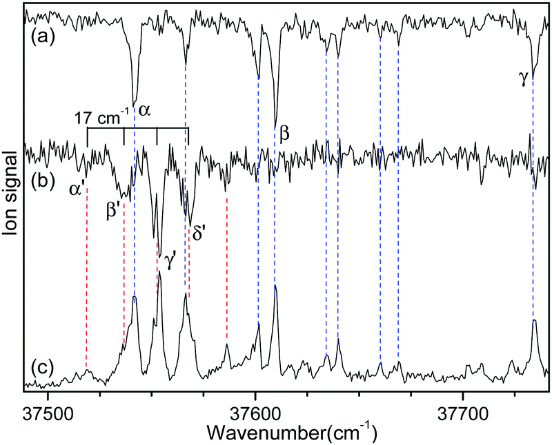 | ||
| Fig. 2 IR-UV HB spectra obtained by fixing an IR pump laser at vibrational bands (a) i and (b) ii in the IR ion-dip spectra in Fig. 1. (c) UVPD spectrum of L-H+PheAla shown for comparison. | ||
Since no other bands were observed in the lower wavenumber than 37 500 cm−1, we assigned the bands α and α′ as the origin bands of conformers I and II, respectively. The band α′, however, does not seem to be the origin band but is more likely a hot band because it is weak and broad. We note that hot bands can appear as dip signals in the IR-UV HB spectrum because the IR ion-dip spectra of hot bands can exhibit the same vibrational bands with the cold bands.40
To determine whether the band α′ is a cold or hot band, we obtained UV-UV HB spectra using the MLS technique. A cold band arises from the transition at the vibrational energy level of v′′ = 0 in the S0 state, whereas a hot band arises from the transition at a vibrationally excited energy level of v′′ > 0. In UV-UV HB spectroscopy, the UV pump laser depletes the population of a certain isomer only at v′′ = 0 or v′′ >0 depending on the UV pump wavelength. Thus, UV-UV HB spectra can separate hot bands from cold bands by fixing the UV pump laser to a cold or a hot band.
Fig. 3a and b show the UV-UV HB spectra of conformers I and II obtained with the UV pump laser fixed at bands β and γ′ in Fig. 2, respectively. As expected, the α band appeared as a dip signal in the HB spectrum of conformer I. In the HB spectrum of conformer II, the band α′ and the bands β′ and γ′ were observed as dip signals, which indicated that the band α′ is not a hot band but a cold band like the bands β′ and γ′; thus, the origin band of conformer II.
 | ||
| Fig. 3 UV-UV HB spectra of conformers (a) I and (b) II obtained by fixing the UV pump laser at the bands β and γ′ in Fig. 2, respectively. (c) UVPD spectrum of L-H+PheAla shown for comparison. | ||
The weak origin band of conformer II may indicate the occurrence of a large structural displacement upon the transition to the S1 state, which is supported by the observation of a vibrational progression with an interval of 17 cm−1 in the IR-UV HB spectrum (Fig. 2b). The band intensities of the vibrational progression may reflect the Franck–Condon factors that indicate the displacement of the equilibrium geometry in the S1 state with respect to that in the S0 state along the coordinate of the vibrational mode at 17 cm−1.
To identify the structures of the conformers, theoretical IR spectra of low-lying conformers of L-H+PheAla were predicted at the CAM-B3LYP/6-311++G(d,p) level and compared with the IR ion-dip spectra. The structures, energies, and theoretical IR spectra of the low-lying conformers are shown in Fig. S2 and S3 (ESI†). The names of the low-lying conformers were adopted from a previous report.35
The IR ion-dip spectra of conformers I and II coincided well with the IR spectra of TransA1 and TransA1′, respectively, among all the low-lying conformers (Fig. 4 and Fig. S3, ESI†). TransA1 and TransA1′ are also the lowest energy conformers predicted at the CAM-B3LYP/6-311++G(d,p) level. Thus, we assigned TransA1 and TransA1′ as conformers I and II, respectively. TransA1 was previously assigned as a dominant conformer of H+PheAla at the room temperature.35
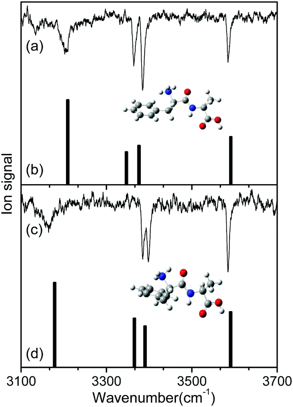 | ||
| Fig. 4 IR ion-dip spectra of conformers (a) I and (c) II in comparison with the theoretical IR spectra of (b) TransA1 and (d) TransA1′. The theoretical spectra were predicted at the CAM-B3LYP/6-311++G(d,p) level with a scale factor of 0.95. The insets in (a) and (c) show the structures of TransA1 and TransA1′, respectively. | ||
Table 1 lists the positions and modes of the vibrational bands in the IR ion-dip spectra. The bands at 3585 cm−1 were assigned as the OH stretching mode of the carboxyl group. The NH stretching modes of the peptide bond in both conformers were observed at ∼3390 cm−1. The vibrational bands at 3364 and 3385 cm−1 in conformers I and II, respectively, were assigned as the asymmetric stretching mode of a free NH bond in the protonated N-terminus. The broad vibrational bands at 3206 and 3164 cm−1 were assigned as asymmetric stretching modes of an NH bond in the protonated N-terminus, which was hydrogen-bonded to the phenyl ring.
| Conformer | ν exp | ν cal | Vibrational mode |
|---|---|---|---|
| a Peak positions in cm−1 of vibrational bands observed in the IR ion-dip spectra. b Peak positions in cm−1 of vibrational bands predicted in the theoretical IR spectra. | |||
| I | 3585 | 3780 | OH stretching |
| 3386 | 3554 | NH stretching | |
| 3364 | 3523 | NH3+ asymmetric stretching | |
| 3206 | 3378 | NH3+ asymmetric stretching | |
| II | 3585 | 3780 | OH stretching |
| 3398 | 3569 | NH stretching | |
| 3385 | 3543 | NH3+ asymmetric stretching | |
| 3164 | 3346 | NH3+ asymmetric stretching | |
Fig. 5 shows the UVPD CD spectra of L- and D-H+PheAla near the origin bands of conformers I and II. Only the α bands of L- and D-H+PheAla had large CD bands, which were mirror images to each other. The CD bands of the other vibronic bands were indistinguishable from the baseline due to their small CD values.
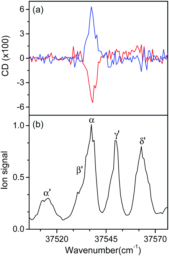 | ||
| Fig. 5 (a) UVPD CD spectra of L-H+PheAla (red) and D-H+PheAla (blue) near the origin bands of conformers I and II obtained using four cycles of the MLS technique. (b) UVPD spectrum of L-H+PheAla shown for comparison. | ||
To measure the small CD values, we performed MLS scans, which recorded FL–FR values at the peak of a vibronic band as a function of the number of cycles, where FL and FR represent fragment signals generated by LCP and RCP pulses, respectively. Because the MLS scans were carried out at a single wavelength, more data can be averaged at the peak of a vibronic band in the MLS scan than in the UVPD spectrum for a given measurement time. Furthermore, the magnitudes of FL–FR usually increase with increasing number of cycles because the numbers of parent and photofragment ions in the QIT grow with the number of cycles.20 Thus, for a vibronic band with a nonzero CD value, FL–FR increases or decreases depending on the CD sign as the number of cycles increases. Hence, the CD sign can easily be determined by the slope of the MLS scan.
Fig. 6a–c show the MLS scans for the bands α, α′, and γ′ of L- and D-H+PheAla, respectively. The FL–FR values of the α band of L-H+PheAla decrease as the number of cycles increases, thus indicating a negative CD sign, which is consistent with the negative CD band in the UVPD CD spectrum (Fig. 5). In contrast, the FL–FR values of the bands α′ and γ′ of L-H+PheAla increase with increasing number of cycles, thus indicating a positive CD sign. These opposite CD signs of the α and α′ bands, which were assigned as the origin bands of conformers I and II, respectively, agree well with the rotatory strength R signs of TransA1 and TransA1′ predicted using TDDFT at the CAM-B3LYP/6-311++G(d,p) level, which further confirms the structural assignments of the conformers (Table 2).
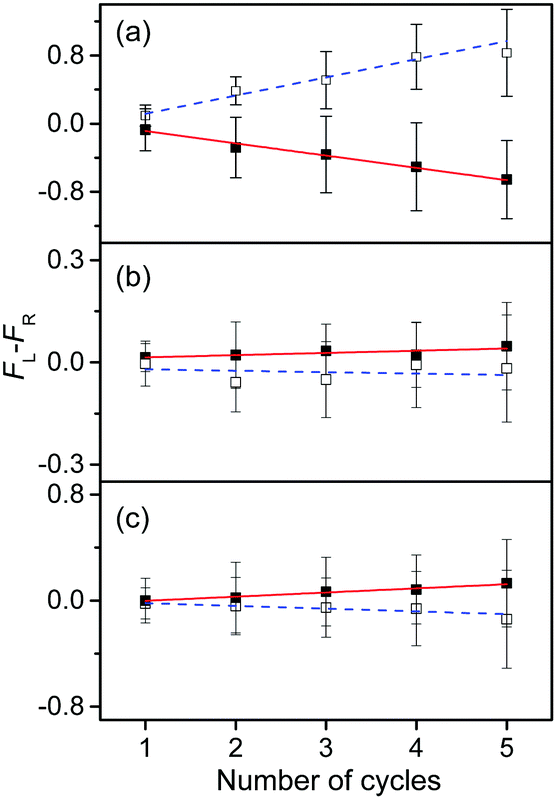 | ||
| Fig. 6 Plots of FL–FRvs. the number of cycles for the bands (a) α, (b) α′, and (c) γ′ of L-H+PheAla (red) and D-H+PheAla (blue). The error bars represent the standard deviations. | ||
| Conformer | R | g |
|---|---|---|
| a Rotatory strengths in cgs (10−40 erg esu cm/Gauss) for TransA1 and TransA1′, which were assigned as conformers I and II, respectively. The R values were predicted using TDDFT at the CAM-B3LYP/6-311++G(d,p) level. b Asymmetry factors in percentage. | ||
| I | −0.99 | −4.5 (α) |
| II | 0.76 | 0.5 (α′) |
| 0.6 (γ′) | ||
The asymmetry factor g was estimated from the plots of the MLS scan, and the results are listed in Table 2. The g value is given by 2(ILCP – IRCP)/(ILCP + IRCP), where ILCP and IRCP are fragment signals produced by LCP and RCP pulses, respectively, using five cycles in the MLS technique.
MLS scans were also performed for bands β′ and δ′ but the slopes were nearly zero, which may indicate that the CD values of β′ and δ′ are too small to be measured using the MLS scan.
Discussion
The most interesting finding is that conformers I and II of L-H+PheAla have significantly different CD values. To provide an explanation for their different CD values, we compared the structures of the two conformers. Table 3 lists the dihedral angles of the conformers in Fig. 7, where ψ, ω, and ϕ determine the structure of the peptide backbone and χ1 and χ2 determine the side-chain conformation of the Phe residue.| Conformer | ψ | ω | ϕ | χ 1 | χ 2 |
|---|---|---|---|---|---|
| I | 166.8 | 174.8 | −160.7 | −51.8 | 102.6 |
| II | −176.6 | −179.1 | −160.5 | 45.1 | 80.1 |
| A | −51.8 | 101.3 | |||
| B | 47.4 | 82.2 |
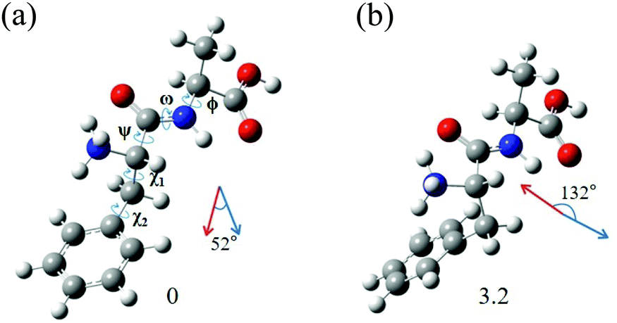 | ||
| Fig. 7 Structures of conformers (a) I and (b) II of L-H+PheAla optimized at the CAM-B3LYP/6-311++G(d,p) level. The dihedral angles of the structures are labeled as ψ, ω, ϕ, χ1, and χ2. The red and blue arrows represent μ and m, respectively. The numbers at the bottom are the relative energies of the conformers in kJ mol−1. | ||
For conformers I and II, the angle of ϕ is nearly identical, while those of ψ and ω seem to be different due to the opposite signs between the two conformers. However, we note that the sign of a dihedral angle represents only the direction of the rotation of one plane with respect to the other, either clockwise or counterclockwise. Hence, although ψ and ω between the two conformers have opposite signs, the differences in their angles are only 16.6° and 6.1°, respectively. These small differences in the angles of ψ, ω, and ϕ between the two conformers indicate that their peptide backbone structures are similar to each other.
The differences in χ1 and χ2 between conformers I and II are 96.9° and 22.5°, respectively. Although the difference in χ2 is moderate, the difference in χ1 is large, indicating that the structural difference between the two conformers mainly results from the different angles of χ1. χ1 determines the orientation of the phenyl ring with respect to the peptide backbone of L-H+PheAla. The angles of χ1 for conformers I and II indicate that their phenyl rings are parallel and perpendicular to the axis of the peptide backbone, respectively.
To determine whether the different orientations of the phenyl ring cause the different CD values of the two conformers, we estimated R values, which were given by the imaginary part of the scalar product between the electric (μ) and magnetic (m) transition dipole moments. Fig. 7 shows the μ and m of conformers I and II for the S0–S1 transition, which were predicted using TDDFT at the CAM-B3LYP/6-311++G(d,p) level. The angles between μ and m in conformers I and II were smaller and larger than 90°, respectively, thus leading to the negative and positive R signs, respectively.
We note that the μ vectors appear to follow the para-axis of the phenyl ring and are very different in their directions between the two conformers. Thus, the different angles between μ and m for the two conformers seem to arise mainly from the different μ vectors rather than the m vectors. Therefore, we suggest that the opposite CD signs of the two conformers are largely due to the different μ vectors which reflect the orientations of the phenyl ring with respect to the peptide backbone.
Although the CD signs of conformers I and II are well reproduced by the R signs, the CD magnitudes are not. The g value of conformer I was 9 times larger than that of conformer II but the R magnitude of conformer I was predicted to be only 1.3 times larger (Table 2). One possible reason for this discrepancy between the experiment and theory is that the R values were estimated by TDDFT, which computed CD values only for the vertical transition between the S0 and S1 states. The experimental CD of the origin band, however, represents the CD of the adiabatic transition between the lowest energy structures at the S0 and S1 states. Thus, the structural changes of conformers I and II occurring during the S0–S1 transition might affect the predicted R values.
We estimated the R values for the adiabatic transition between the S0 and S1 states at the CAM-B3LYP/6-311++G(d,p) level, considering Franck–Condon and Herzberg–Teller contributions at the harmonic level.41–43 It was found that the R signs of conformers I and II for the adiabatic transition were consistent with those for the vertical transition. However, the R magnitude of conformer I was only 1.7 times larger than that of conformer II, which was similar to that of the vertical transition and still less than the experimental value. Further investigation is necessary to understand the reason for the discrepancy in the relative CD values of conformers I and II between the experiment and theory.
The χ1 and χ2 of conformers I and II are very close to those of conformers A and B of L-H+Phe, respectively (Table 3).20 These similarities in the angles χ1 and χ2 indicate that the structures of the Phe residues in conformers I and II are similar to those of conformers A and B, respectively. Indeed, the CD signs of conformers I and II correspond to those of conformers A and B, respectively. However, their CD magnitudes are very different. Although the g value of conformer I is similar to that of conformer A (−4.0%), the g value of conformer II is 3 times smaller than that of conformer B (+2.0%). These results may imply that although the formation of a peptide bond with Ala has little effect on the CD signs of H+Phe conformers, it has a significant effect on their CD magnitudes.
Conclusions
We obtained the CD spectra of L-H+PheAla ions produced by ESI using cryogenic ion spectroscopy. IR-UV and UV–UV double resonance spectroscopy showed that L-H+PheAla ions existed as two different conformers in the cryogenic ion trap. The two conformers had similar peptide backbone structures but different side-chain conformations of the Phe residue. The CD signs of the two conformers were opposite to each other and their CD magnitudes differed by an order of magnitude. These results demonstrate that the CD values of L-H+PheAla ions near the origin band of the S0–S1 transition are greatly influenced by the side-chain conformation of the Phe residue. Further investigation of L-H+PheAlaAla or L-H+AlaPheAla may help clarify the relationships between the side-chain conformations of the Phe residue and the CD spectra in the near-UV region.Author contributions
I. T. Y. and H. J. E. performed the experiments and theoretical calculations. A. M., C. W. J, and J. J. helped the experiments, and J. H. contributed the theoretical analysis. I. T. Y., H. J. E., and N. J. K. contributed to the analysis and discussion of the results and the preparation of the manuscript.Conflicts of interest
There are no conflicts to declare.Acknowledgements
This work was financially supported by the Samsung Science and Technology Foundation under Project Number SSTFBA1602-06.Notes and references
- B. Norden, A. Rodger and T. Dafforn, Linear Dichroism and Circular Dichroism, The Royal Society of Chemistry, Cambridge, 2010 Search PubMed.
- S. M. Kelly, T. J. Jess and N. C. Price, Biochim. Biophys. Acta, 2005, 1751, 119–139 CrossRef CAS.
- G. Siligardi, R. Hussain, S. G. Patching and M. K. Phillips-Jones, Biochim. Biophys. Acta, 2014, 1838, 34–42 CrossRef CAS PubMed.
- S. M. Kelley and N. C. Price, Curr. Protein Pept. Sci., 2000, 1, 349–384 CrossRef PubMed.
- N. Sreerama, M. C. Manning, M. E. Powers, J. X. Zhang, D. P. Goldenberg and R. W. Woody, Biochemistry, 1999, 38, 10814–10822 CrossRef CAS PubMed.
- Z. Li and J. D. Hirst, Chem. Sci., 2017, 8, 4318–4333 RSC.
- A. Hong, C. M. Choi, H. J. Eun, C. Jeong, J. Heo and N. J. Kim, Angew. Chem., Int. Ed., 2014, 53, 7805–7808 CrossRef CAS PubMed.
- R. Li, R. Sullivan, W. Al-Basheer, R. M. Pagni and R. N. Compton, J. Chem. Phys., 2006, 125, 144304 CrossRef CAS PubMed.
- U. Boesl and A. Kartouzian, Annu. Rev. Anal. Chem., 2016, 9, 343–364 CrossRef CAS PubMed.
- C. Loge and U. Boesl, Chem. Phys. Chem., 2011, 12, 1940–1947 CrossRef CAS PubMed.
- G. A. Garcia, H. Dossmann, L. Nahon, S. Daly and I. Powis, Chem. Phys. Chem., 2017, 18, 500–512 CrossRef CAS PubMed.
- I. Powis, Photoelectron Circular Dichroism in Chiral Molecules, Wiley, New Jersey, 2008 Search PubMed.
- I. Powis, J. Chem. Phys., 2000, 112, 301–310 CrossRef CAS.
- I. Powis, J. Phys. Chem. A, 2000, 104, 878–882 CrossRef CAS.
- G. A. Garcia, L. Nahon, M. Lebech, J.-C. Houver and D. Dowek, J. Chem. Phys., 2003, 119, 8781–8784 CrossRef CAS.
- M. M. R. Fanood, N. B. Ram, C. S. Lehmann, I. Powis and M. H. M. Janssen, Nat. Commun., 2015, 6, 1–8 Search PubMed.
- T. Muller, K. B. Wiberg and P. H. Vaccaro, J. Phys. Chem. A, 2000, 104, 5959–5968 CrossRef.
- A. S. Perera, J. Cheramy, M. R. Poopari and Y. Xu, Phys. Chem. Chem. Phys., 2019, 21, 3574–3584 RSC.
- N. M. Kreienborg, J. Bloino, T. Osowski, C. H. Pollok and C. Merten, Phys. Chem. Chem. Phys., 2019, 21, 6582–6587 RSC.
- H. J. Eun, A. Min, C. W. Jeon, I. T. Yoo, J. Heo and N. J. Kim, J. Phys. Chem. Lett., 2020, 11, 4367–4371 CrossRef CAS PubMed.
- S. Daly, F. Rosu and V. Gabelica, Science, 2020, 368, 1465–1468 CrossRef CAS PubMed.
- P. Kruger and K. M. Weitzel, Angew. Chem., Int. Ed., 2021, 60, 17861–17865 CrossRef PubMed.
- M. Yamashita and J. B. Fenn, J. Phys. Chem., 1984, 88, 4451–4459 CrossRef CAS.
- J. A. Noble, C. Dedonder-Lardeux, J. Mascetti and C. Jouvet, Chem.-Asian J., 2017, 12, 1523–1531 CrossRef CAS PubMed.
- O. V. Boyarkin, S. R. Mercier, A. Kamariotis and T. R. Rizzo, J. Am. Chem. Soc., 2006, 128, 2816–2817 CrossRef CAS PubMed.
- A. B. Wolk, C. M. Leavitt, E. Garand and M. A. Johnson, Acc. Chem. Res., 2014, 47, 202–210 CrossRef CAS PubMed.
- S.-i. Ishiuchi, H. Wako, D. Kato and M. Fujii, J. Mol. Spectrosc., 2017, 332, 45–51 CrossRef CAS.
- Y. Inokuchi, O. V. Boyarkin, R. Kusaka, T. Haino, T. Ebata and T. R. Rizzo, J. Am. Chem. Soc., 2011, 133, 12256–12263 CrossRef CAS PubMed.
- K. C. Fischer, S. L. Sherman, J. M. Voss, J. Zhou and E. Garand, J. Phys. Chem. A, 2019, 123, 3355–3366 CrossRef CAS PubMed.
- D. Gerlich, in Low temperatures and cold molecules, ed. I. W. M. Smith, Imperial College Press, London, 2008, ch. 3, pp. 121–174 Search PubMed.
- M. Gerhards and C. Unterberg, Phys. Chem. Chem. Phys., 2002, 4, 1760–1765 RSC.
- M. Gerhards, C. Unterberg, A. Gerlach and A. Jansen, Phys. Chem. Chem. Phys., 2004, 6, 2682–2690 RSC.
- W. Chin, F. Piuzzi, J. P. Dognon, I. Dimicoli and M. Mons, J. Chem. Phys., 2005, 123, 084301 CrossRef PubMed.
- J. Mahe, D. J. Bakker, S. Jaeqx, A. M. Rijs and M.-P. Gaigeot, Phys. Chem. Chem. Phys., 2017, 19, 13778–13787 RSC.
- R. C. Dunbar, J. D. Steill, N. C. Polfer and J. Oomens, Int. J. Mass Spectrom., 2009, 283, 77–84 CrossRef CAS.
- H. Kang, G. Feraud, C. Dedonder-Larduex and C. Jouvet, J. Phys. Chem. Lett., 2014, 5, 2760–2764 CrossRef CAS PubMed.
- A. Hong, H. Jang, C. Jeong, M. C. Choi, J. Heo and N. J. Kim, J. Phys. Chem. Lett., 2016, 7, 4385–4390 CrossRef CAS PubMed.
- H. Goto and E. Osawa, J. Chem. Soc., Perkin Trans. 2, 1993, 187–198 RSC.
- M. J. Frisch, G. W. Trucks, H. B. Schlegel, G. E. Scuseria, M. A. Robb, J. R. Cheeseman, G. Scalmani, V. Barone, B. Mennucci and G. A. Petersson, et al., Gaussian 09, Revision A.01, Gaussian, Inc., Wallingford CT, 2009 Search PubMed.
- W. Y. Sohn, S.-i. Ishiuchi, M. Miyazaki, J. Kang, S. Lee, A. Min, M. Y. Choi, H. Kang and M. Fujii, Phys. Chem. Chem. Phys., 2013, 15, 957–964 RSC.
- J. Bloino, M. Biczysko, O. Crescenzi and V. Barone, J. Chem. Phys., 2008, 128, 244105 CrossRef PubMed.
- N. Lin, F. Santoro, X. Zhao, A. Rizzo and V. Barone, J. Phys. Chem. A, 2008, 112, 12401–12411 CrossRef CAS PubMed.
- M. J. Frisch, G. W. Trucks, H. B. Schlegel, G. E. Scuseria, M. A. Robb, J. R. Cheeseman, G. Scalmani, V. Barone, G. A. Petersson and H. Nakatsuji, et al., Gaussian 16, Revision A.03, Gaussian, Inc., Wallingford, CT, 2016 Search PubMed.
Footnotes |
| † Electronic supplementary information (ESI) available: Mass spectrum of L-H+PheAla and the optimized structures, relative energies, and theoretical IR spectra of the low-lying conformers of L-H+PheAla. See DOI: 10.1039/d1cp04030h |
| ‡ These authors contributed equally. |
| This journal is © the Owner Societies 2021 |