Mesoscale triphasic flow reactors for metal catalyzed gas–liquid reactions†
Dogancan
Karan
and
Saif A.
Khan
 *
*
Department of Chemical and Biomolecular Engineering, National University of Singapore, 4 Engineering Drive 4, E5-02-28, 117576 Singapore. E-mail: saifkhan@nus.edu.sg
First published on 11th June 2019
Abstract
In this study, we demonstrate a mesoscale triphasic (gas–liquid–liquid) reactor for fast, transition metal catalyzed gas–liquid reactions, which is capable of delivering kg per day productivity at the single channel level. More generally, our study addresses the limits of scale up of multiphase flow reactors beyond the micro- and milli-scale. We first conduct a rigorous hydrodynamic study that allows us to explore the channel dimension and reactor operating conditions within which a stable and regular flow regime can be maintained. We particularly focus on the presence of the organic phase as a thin film around the train of dispersed phase segments, since this plays a key role in process intensification and flow stability. A tube diameter of 3.2 mm is found to be the upper limit for the mesoscale channel, beyond which thin films cease to exist due to combination of gravitational drainage and dewetting. Next, we present experimental observations of a model reaction – the hydrogenation of 1-hexene in the presence of a rhodium nanoparticle catalyst (RhNP) to evaluate the reactor performance and highlight the key differences between micro/milli-scale and mesoscale operation. Finally, we develop and discuss a mathematical model that accurately captures the key experimental observations. Based on the insight we gain from our model, we demonstrate further scale up of the reactor to achieve the performance of >100× equivalent milliscale flow reactors with a single mesoscale channel under ambient conditions.
1. Introduction
Drug substances and active pharmaceutical ingredients (APIs) differ significantly in molecular complexity when compared to commodity chemicals, and their manufacture generally requires a cascade of synthetic steps, in which transition metal catalyzed gas–liquid reactions such as hydrogenation, oxidation, and carbonylation play a common role.1 In the pharmaceutical industry, these latter reactions are conventionally carried out in stirred batch tanks in which a gaseous reactant is pressurized on the top of the liquid phase, which contains solvent, substrates, and catalyst particles. However, the performance of such reactors is almost always limited by poor heat and mass transfer rate due to small interfacial areas and inefficient contacting of different fluid phases. Continuous flow microreactors offer remarkably accelerated heat and mass transport rate due to small characteristic dimensions which provides several orders of magnitude higher interfacial area compared to conventional macroscale gas–liquid contactors.2 Furthermore, the small characteristic dimension results in surface tension-dominated flow, which enables regular and stable multiphase flow regimes, in turn allowing fine control over reaction conditions and transport properties. In view of the advantages that small-scale systems offer, different microreactor platforms and configurations3–8 have been developed to carry out various gas–liquid transformations6,9–12 over the past decade.However, despite the numerous advantages, operation in sub-millimeter channels severely constrains the productivity of such reactors, posing major challenges in their application for larger scale production.13 Unlike conventional reactors, increasing the throughput of the microreactors is not as straightforward as increasing reactor dimension and/or volumetric flow rate of the reactants, especially for the case of multiphase reactions, since heat and mass transport performance and hydrodynamic behavior of the reactor are quite sensitive to characteristic dimension of the system as well as volume fraction of individual fluid phases.14 High throughput production in microreactors can be realized by numbering-up (parallelization or scaling-out), in which multiple individual channels are operated simultaneously.15–21 By doing so, the same hydrodynamic conditions in each elementary channel can be maintained while achieving higher production rates.
There are several engineering challenges which hinder exploitation of scaled-out microreactor networks. The key engineering challenge is to provide equal fluid distribution to different channels, in that good global reactor performance can only be realized by excellent consistency of reaction conditions among elementary reactor channels.22–24 This problem has been well addressed in gas–liquid and liquid–liquid segmented flow configurations by using high-pressure drop zones across a fluid distributor which eliminate the variation in downstream pressure drop, and equal fluid distribution can be achieved.25–27 However, minute differences in pressure drops can result in maldistribution or even gas–liquid channeling which severely affects the overall consistency of the reactor network. Such a crucial engineering challenge requires sophisticated monitoring and control systems, which further increases the complexity of the reactor network.22 More importantly, hundreds or even thousands of parallel microchannels may be required to achieve commercial-scale production, which makes increasing the throughput solely by numbering-up quite impractical. Therefore, with all the existing challenges, we contend that scaling-up by increasing the characteristic channel dimension is still a viable route to enable large-scale applications of such reactors. Indeed, the best approach would be to find an intermediate mesoscale channel size which provides sufficiently high heat and mass transport rate along with higher production rate which allows to further increase the throughput by means of reasonable number of parallel reactor units to minimize the overall complexity of the reactor system.
Our research group has previously demonstrated a gas–liquid–liquid triphasic millireactor28,29 for fast, metal-catalyzed reactions where catalyst was immobilized in a separate liquid phase for facile recovery and recycle. More recently, we have demonstrated design and operation of 8-fold parallelized triphasic millireactor network21 with online catalyst recovery and recycle. The reactor setup employs resistance-based fluid distributors and capacitance-based hydraulic dampers to maintain consistency between elementary channels. In this study, we report the design and operation of a mesoscale reactor to push the limits of the triphasic millireactor setup for large-scale applications. A mesoscale channel retains the basic physics of operation of small-scale systems – accelerated transport rate, regular and consistent flow regime, yet provides significantly more throughput due to its unique intermediate size. It is worthwhile to note that increasing throughput via scaling-up is achieved at the expense of lower interfacial area and hence lower mass transport rate. Under comparable conditions, smaller channels provide better mass transport performance. This paper is organized three main parts. We first present a rigorous hydrodynamic study that allows us to explore the channel dimension and reactor operating conditions within which a stable and regular flow regime can be maintained. Next, we present experimental observations of a model reaction – the hydrogenation of 1-hexene in the presence of a rhodium nanoparticle catalyst (RhNP) to evaluate the reactor performance and highlight the key differences between micro/milli-scale and mesoscale operation. Finally, we develop and discuss a mathematical model that accurately captures the key experimental observations. Based on the insight we gain from our model, we demonstrate further scale up of the reactor to achieve the performance of >100× equivalent milliscale flow reactors with a single mesoscale channel under ambient conditions.
2. Materials and methods
2.1. Rhodium nanoparticle synthesis
Rhodium nanoparticles were synthesized by the ethanol-reduction method.30 First, a 5 mM precursor solution was prepared with 66.8 mg of RhCl3·xH2O (Alfa Aesar Rh 38.5–45.5%), 0.555 g of polyvinylpyrrolidone (PVP, Alfa Aesar, molecular weight: 40![[thin space (1/6-em)]](https://www.rsc.org/images/entities/char_2009.gif) 000 g mol−1) as stabilizer, 30 mL of absolute ethanol (Fischer Scientific, 99.5%) as reducing agent, and 20 mL of ultrapure water (Milli-Q, 18.2 MΩ cm at 25 °C). The solution was refluxed at 115 °C for 1 hour, with a stirrer set at 575 RPM in the reflux flask. Thereafter, all solvent was evaporated in a rotary evaporator (Buchi R-210 Rotavapor) at 45 °C under vacuum to obtain a black residue at bottom of the volumetric flask. Finally, the black residue was dispersed into 50 mL ultrapure water to obtain a ‘5 mM’ rhodium nanoparticle stock solution, which was subsequently stored at 5 °C. Since PVP is a soluble polymer in polar solvents, rhodium nanoparticles can be suspended in water as a colloidally-stable solution. The stock solution was diluted 5× to 1 mM prior to hydrogenation experiments. The quality of nanoparticles was checked by TEM (JEOL 2010, accelerating voltage 200 kV). The average particle size was found to be 3.8 ± 0.8 nm (see ESI† Fig. S1 for the TEM picture of rhodium nanoparticles).
000 g mol−1) as stabilizer, 30 mL of absolute ethanol (Fischer Scientific, 99.5%) as reducing agent, and 20 mL of ultrapure water (Milli-Q, 18.2 MΩ cm at 25 °C). The solution was refluxed at 115 °C for 1 hour, with a stirrer set at 575 RPM in the reflux flask. Thereafter, all solvent was evaporated in a rotary evaporator (Buchi R-210 Rotavapor) at 45 °C under vacuum to obtain a black residue at bottom of the volumetric flask. Finally, the black residue was dispersed into 50 mL ultrapure water to obtain a ‘5 mM’ rhodium nanoparticle stock solution, which was subsequently stored at 5 °C. Since PVP is a soluble polymer in polar solvents, rhodium nanoparticles can be suspended in water as a colloidally-stable solution. The stock solution was diluted 5× to 1 mM prior to hydrogenation experiments. The quality of nanoparticles was checked by TEM (JEOL 2010, accelerating voltage 200 kV). The average particle size was found to be 3.8 ± 0.8 nm (see ESI† Fig. S1 for the TEM picture of rhodium nanoparticles).
2.2. Triphasic flow visualization
For flow visualization, two 2 m long polytetrafluoroethylene (PTFE) reactor tubes of 3.2 mm and 4 mm ID respectively were chosen, since PTFE facilitates the wetting of reactor wall by the organic phase. Flow visualization was conducted under non-reactive conditions. Due to the large excess of gas supplied during the reaction, the volume change of gas bubbles is negligible, as will be discussed below; therefore, using non-reactive conditions is suitable for flow visualization.29 A liquid–liquid segmented flow was formed at the first T junction (Swagelok, 3 mm ID) by introducing blue food dye solution from one arm and decane (ReagentPlus, Sigma-Aldrich, ≥99%) from the other arm via two syringe pumps (Harvard Apparatus PhD 2000, Programmable) at different volumetric flow rates. Blue food dye was used to distinguish the aqueous phase under the camera. Nitrogen gas was introduced from the second T-junction (Swagelok, 3 mm ID) at atmospheric pressure to form gas–liquid–liquid segmented flow at different volumetric flow rates. 20 cm long high-resistance polyether ether ketone (PEEK) tubes of 100 μm ID were used to fine tune the volumetric gas flow rate prior to feeding into the reactor channel. A schematic representation of the experimental setup is shown in Fig. 1. A microscope system, which was placed 30 cm away from the second T-junction was used to observe and record the flow pattern in the reactor channel; the system was composed of a 200-fps high-speed camera (Basler piA640-210gm) fitted to an optical microscope (Leica MZ16) and a light source at the bottom of the reactor channel. Bubble flow speeds, generation frequencies/periods and residence times were determined from high-speed videos recorded at different frame rates; statistics from at least 100 bubbles were used for each experimental condition. It is worthwhile to highlight that the different bubble residence times, lengths of the gas bubbles and hence the volumetric flow rate of the gas phase are adjusted by changing the gas pressure from the tank. Volumetric flow rate of gas phase used in our experiments ranged between 12 mL min−1 to 146 mL min−1, while the total liquid flow rates used ranged between 0.4 to 4.8 mL min−1. Since the volumetric flow rate of the gas phase is several orders of magnitude higher than that of liquid phase, changing the volumetric flow rate of the liquid phase (organic or aqueous) does not appreciably affect the bubble residence time. In addition, we estimated the change in the bubble length due to hydrogen consumption under different reactive flow conditions to be in the range of 5–15%, highlighting the fact that the volumetric flow rate of gas does not appreciably change as it flows through the reactor.2.3. Hydrogenation in the mesoreactor
The experimental system described above was set up for 3.2 mm ID PTFE tube for various experimental conditions except that nitrogen gas was replaced with hydrogen gas and blue food dye solution was replaced with rhodium nanoparticle solution to provide the reactive conditions. Before the reaction was started, the reactor was primed with organic substrate mixture for 15 minutes with a flow rate of 0.3–0.9 mL min−1 to facilitate wetting and shorten the time to reach steady state. In order to prevent liquid back flowing to the gas line, 12 mL min−1 hydrogen gas was fed to the reactor along with organic phase during the start-up period. During the shut-down, ethanol and acetone were introduced to reactor channel to remove any residual catalyst and substrate mixture for another 15 minutes. 100 μL reactor effluent was collected in vials and diluted with 1200 μL diethyl ether (Fischer Scientific ≥ 99%) and analyzed by gas chromatography (Shimadzu 2010 Plus). All GC measurements were conducted off-line. Three samples were collected for each data point. All experiments were performed at atmospheric pressure and room temperature and were conducted in duplicate. Experimental runs were carried out on different days with freshly prepared rhodium nanoparticle catalyst (RhNP) solution to calculate the error bars.2.4. Design and testing of hydraulic dampers for scaled-up synthesis
For the scaled-up synthesis, syringe pumps were replaced with peristaltic pumps, and hydraulic dampers were introduced into the fluid delivery lines before they joined the reactor. Hydraulic dampers were used to eliminate the pressure fluctuations introduced by peristaltic pumps to sustain the robust multiphase flow regime. Two different hydraulic dampers were designed for organic and aqueous fluid streams in accordance with desired flow rates. The design criteria were obtained from a recent study by Yap et al.21 For the aqueous fluid stream, a 12 cm long #25 silicone tube (7.94 mm OD, Masterflex) was sandwiched between two 10 cm long 228 μm ID polyether ether ketone (PEEK) tubes. For the organic fluid stream, a 12 cm #25 Viton tube (6.35 mm OD, Cole Parmer) was sandwiched between two 11 cm long 152 μm ID polyether ether ketone (PEEK) tubes. The reliability of the dampers was tested by a liquid flowmeter (Sensirion, SLQ-QT500), with peristaltic pumps (Leadfluid BT-100S), and measuring the volume of different liquid samples. The deviation in the flow rate was found to be <2% for both streams.3. Results and discussion
3.1. Mesoscale flow systems – defining the limits of scale-up
The first question we address in this study is that of scale-up; specifically, we ask – how much can the flow channel be enlarged beyond the ‘micro’ (∼0.01–0.1 mm) and ‘milli’ (∼1 mm) scale before the advantage of highly regular flow patterns is lost? In multiphase flows (gas–liquid, liquid–liquid, etc.) through micro and milli-scale channels, gravitational and inertial forces are negligible, whereas viscous and interfacial forces are dominant; this situation is reflected by the typically low (<0.01) Capillary and Bond numbers in such channels.14 This leads to extremely regular flow regimes, such as the segmented/Taylor flow regime, which has been well studied and applied in flow chemistry over the past decade.6,9,10,31However, as the characteristic dimension of the channel increases, the balance between these forces alters; specifically, gravitational forces start becoming comparable to interfacial forces. An estimate of a crossover dimension may be obtained by considering the Bond number (Bo), which is the ratio of hydrostatic pressure to Laplace pressure, as shown below:32
 | (1) |
Equating the Bond number to unity yields a length scale L of ∼3 mm for an air-water system. Therefore, for all subsequent studies highlighted in this paper, we use two channel diameters in this size range (3.2 mm and 4 mm respectively) to illustrate important phenomena at the crossover of scales at which gravitational (and inertial) effects cannot be ignored in a triphasic gas–liquid–liquid flow. Further, we define a baseline for robust and ‘regular’ flow as being comprised of a perfectly regular pattern of alternating gas bubbles and aqueous drops, all encapsulated by a thin film of the organic liquid, as schematically depicted in Fig. 1, and reported in previous work from our group.29,33
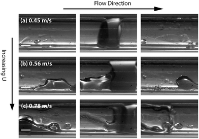
Experimental stereomicroscopic images of gas–liquid–liquid flow in the two different channel sizes at different bubble flow speeds are shown in Fig. 2 and 3, respectively. In both channels, well-defined aqueous drop/plugs surrounded by organic liquid and located between gas bubbles were observed at flow speeds of 0.005–0.36 m s−1. The first phenomenon of note is the state of the organic films, which will have crucial implications on reactor performance, as will be discussed later in the paper. In the 4 mm ID channel, dewetting and breakage of the organic film surrounding the gas bubbles was observed at all flow speeds (Fig. 2a–d; also see movie M1 in the ESI†) whereas the same phenomenon was observed at only low flow speeds (0.005–0.01 m s−1) in the 3.2 mm ID channel (Fig. 3a and b; also see movie M2 in the ESI†). Breakage and dewetting of the organic film at high flow speeds is an important indicator of the crossover from a surface tension-dominated flow regime to a gravity-dominated one in 4 mm channel. For a detailed discussion and explanation of the physics of film breakage, we refer the interested reader to section 2 of the ESI† and its associated references. The second phenomenon of note is the effect of flow velocity beyond the range illustrated in Fig. 2 and 3. As the velocity was increased further beyond this range, we observed increasing instances of droplet rupture/breakup and unstable flows, as shown in Fig. 4 (also see movie M3 in the ESI†). The third phenomenon of note is the flattened shape of the gas–organic and organic–aqueous interfaces (Fig. 3c). Similar observations have been previously reported in studies of gas–liquid–liquid segmented flow in circular34 and square geometries.33 This arises from the difference in translational speeds between aqueous drops and gas bubbles. Therefore, the interfacial organic film between the aqueous drops and gas bubbles rapidly drains out and redistributes as an annular film around the gas bubbles. As the film is squeezed out, a lubrication pressure is built up which is high enough to invert the curvature of the droplet/bubble caps and flattens the gas–aqueous fluid interface as highlighted in Fig. 3c (also see ESI† Fig. S2). Nevertheless, the interfacial film does not drain out completely. The lubrication pressure prevents the film from draining further and it reaches a constant thickness,35,36 which has important implications on reactor performance, as we will discuss below. We can reasonably hypothesize that the thickness of the interfacial film between the aqueous drop and gas bubble (see Fig. 1) does not depend strongly on the volumetric flow rate of the organic phase; instead, increasing the organic flow rate will result in thicker annular films surrounding the gas bubbles due to fluid redistribution.
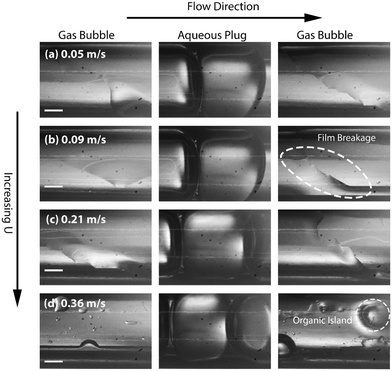 | ||
| Fig. 2 (a)–(d) High-speed stereomicroscope images of gas–liquid–liquid segmented flow at different flow velocities in 2 m long 4 mm ID PTFE channel highlighting the breakage of the organic film around the gas bubbles. BoL–L = 0.9, BoG–L = 4.8, where subscripts L–L and G–L represent organic–aqueous interface and organic–gas interface, respectively. The values of γL–L = 0.0512 N m−1, γG–L = 0.0239 N m−1, and Δρ = 730 kg m−3 were used to calculate the Bond numbers. An example of film breakage due to gravity is shown a dashed circle in Fig. 2b and an example of organic island deposited on the reactor wall is shown a dashed circle in Fig. 2d. QOrg = 0.1 mL min−1, QAq = 0.3 mL min−1, QGas = 19 mL min−1, 33 mL min−1, 70 mL min−1, 121 mL min−1 respectively. Channel walls cannot be seen in the picture due to magnification. All scale bars represent 1 mm. | ||
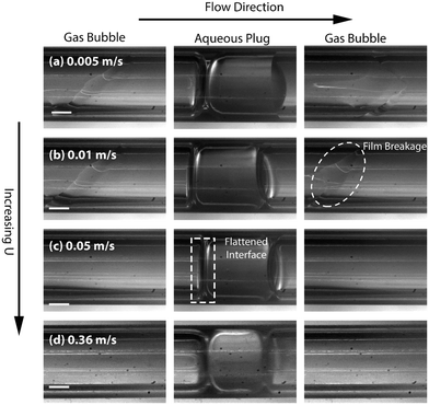 | ||
| Fig. 3 (a)–(d) High-speed stereomicroscope images of gas–liquid–liquid segmented flow at different flow velocities in 2 m long 3.2 mm ID PTFE channel highlighting situation of the organic film around the gas bubbles and the shape of the aqueous droplet/gas bubble meniscus. BoL–L = 0.5, BoG–L = 3. An example of dewetting of the organic liquid is shown a dashed circle in Fig. 3b and an example of flattened gas–aqueous interface is shown a dashed rectangle in Fig. 3c. QOrg = 0.1 mL min−1, QAq = 0.3 mL min−1, QGas = 1.2 mL min−1, 3 mL min−1, 12 mL min−1, 80 mL min−1 respectively. All scale bars represent 1 mm. | ||
Finally, in the light of the collective observations from Fig. 2–4 and the discussion above, we limited further investigations on reactive flows to the 3.2 mm ID tube and flow velocities in the range of 0.05–0.365 m s−1 at which breakage of the organic film and droplet breakups are absent (see ESI† section 3 and movie M4). The presence of the organic films around the gas bubbles improves the multiphase flow stability by eliminating start-stop dynamics29,37 and enhances the mass transport performance of the reactor, as we will discuss in detail below.
3.2. Rhodium nanoparticle catalyzed flow hydrogenation of 1-hexene
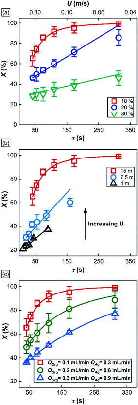
In this section, we use the rhodium nanoparticle (RhNP)-catalyzed hydrogenation of 1-hexene as a model reaction (see Fig. 5) to summarize key features of observed reactor behavior, which we then explain in the subsequent section. Collectively, the experimental observations reported in Fig. 6 and subsequent explanations underscore the important differences in moving from micro- and milli-scale systems of past studies29 to the larger ‘meso’ scale systems of this study.Fig. 6a is a plot of substrate conversion versus bubble residence time and examines the effect of substrate (1-hexene) starting concentration for a fixed reactor length (LR) of 15 m. Residence time was calculated as reactor length LR divided by flow speed U of the gas bubbles (as measured from recorded high-speed flow videos). We make two observations from this plot. Firstly, conversion monotonically increases with residence time as expected. Secondly, and more surprisingly, the curves at the two higher starting substrate concentrations (1.6 M and 2.4 M) show markedly different (zero-order) behavior as compared to the first order behavior at lower concentration (0.8 M). Also, nearly complete conversion is obtained within a residence time of ∼5 min for the 0.8 M case.
Fig. 6b is also a plot of substrate conversion versus bubble residence time and illustrates the effect of the reactor length, which was varied between 4.5 to 15 meters, under otherwise identical conditions. Once again, a transition from zero to first order behavior was observed with increasing reactor length. Equally interesting is the observation that the progressively smaller conversions were observed with decreasing reactor length, at the same residence times. Before we dive into the full explanation for this interesting behavior in the following section below, we note that longer reactors require higher flow speeds for the same residence time as shorter reactors, and flow speeds mediate mass transfer rates in the system. In our study, as already mentioned above, these flow speeds were adjusted by varying gas delivery rate into the system through a pressure regulator.
Finally, Fig. 6c summarizes the effect of total volumetric liquid flow rate (QT = QOrg + QAq) on substrate conversion as a function of bubble residence time. Three different values of QT were studied, from 0.4 mL min−1 to 1.2 mL min−1, while maintaining a constant organic to aqueous flow ratio of 1![[thin space (1/6-em)]](https://www.rsc.org/images/entities/char_2009.gif) :
:![[thin space (1/6-em)]](https://www.rsc.org/images/entities/char_2009.gif) 3. Interestingly, at the same residence time, the observed conversion fell with increasing liquid flow rate QT, and no zero-order behavior was observed at all. For a further discussion of additional notable observations about bubble sizes in these experiments, we refer the reader to section 4 of the ESI.†
3. Interestingly, at the same residence time, the observed conversion fell with increasing liquid flow rate QT, and no zero-order behavior was observed at all. For a further discussion of additional notable observations about bubble sizes in these experiments, we refer the reader to section 4 of the ESI.†
In the section 3.3, we develop a detailed description of reactor behavior in the form of a mathematical model that captures and unifies all the above disparate observations, ultimately enabling design of a scaled-up version of the reactor described in section 3.4.
3.3. Understanding mesoscale multiphase reactor behavior
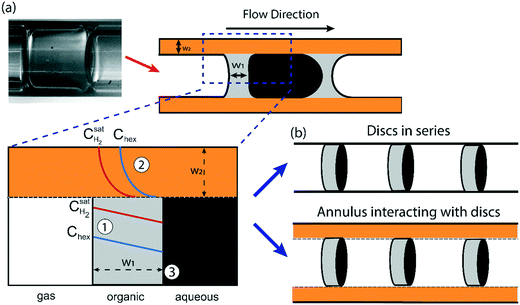
Understanding the various aspects of reactor behavior shown in Fig. 6 requires us to start with a local picture of molecular transport and chemical reaction in the vicinity of any aqueous catalyst plug, as schematically depicted in Fig. 7a. The aqueous catalyst plug is surrounded by two distinct regions of organic liquid – a thick annular film around the reactor walls (region 2 in Fig. 7a) and a thinner ‘interfacial’ film (region 1 in Fig. 7a) immediately adjacent to the flattened aqueous–organic interface. The chemical reaction is assumed to take place nearly instantaneously at the aqueous–organic interface29 and no reaction occurs inside the aqueous plug due to negligible solubility of 1-hexene in water. Therefore, the observed reaction rate is ultimately governed by how fast 1-hexene or hydrogen can be transported from the annular and interfacial film regions to this interface. It is also reasonable to assume that, given the long bubble lengths compared to the aqueous plug lengths (plug/bubble length ratio varies between 1/5 and 1/80), the annular film is always saturated with hydrogen and there is negligible hydrogen depletion within both the annular film and the bubbles. A detailed derivation of the model and description of the assumptions are presented in section 5 of the ESI;† we present the key elements of this model and highlight its explanatory power below.Firstly, when the conversion is lower than the 60–65% range, such as in Fig. 6a (20% and 30% v/v 1-hexene) and Fig. 6b (7.5 m and 4 m of reactor length), the observed reaction rate is controlled entirely by the rate at which molecular hydrogen can be transported from the bubbles and across the interfacial film to the aqueous–organic interface, similar to the case of millifluidic reactors.29 Since this transport is entirely a steady state diffusive process, an appropriate expression for this rate is given by eqn (2) below, where w1 is the interfacial film thickness. Most notably, this equation describes a zero-order process, as clearly seen in the experimental observations.
 | (2) |
Secondly, when the conversion is higher than the range mentioned above, such as in Fig. 6a and b and 5c (10% v/v 1-hexene), there is a considerable depletion of 1-hexene around the aqueous catalyst plug, and the observed rate is now controlled by the molecular transport of 1-hexene to the aqueous–organic interface. This transport occurs from the interfacial film and from the annular film, as captured by eqn (3) below, where w2 is the thickness of the annular film and n is the number of interfacial film regions in the reactor of length LR. This simple model captures the fact that molecular transport of 1-hexene across the annular film region is an unsteady diffusive process, unlike the interfacial film (see ESI† for details). Crucially, this equation describes a first-order process, as clearly seen in the experimental observations of Fig. 6. Such transitions from zero order to first order kinetics have been observed in both millireactors29 as well as conventional batch reactors.38,39 Finally, the above dual-region description of hexene-limited transport perfectly captures the experimental observations of Fig. 6c.
 | (3) |
The thickness of the two film regions, w1 and w2 were fitted to the experimental data (fitting was done in MATLAB via a non-linear least squares method) of Fig. 6a–c; the model curves show excellent fit to the measured data. It is important to note that the model curves overpredict the experimental data in Fig. 6a (20% substrate concentration) and Fig. 6b (7.5 m reactor length) at high conversions (above ∼60%). This situation is a result of a transition in the dominant mass transport mechanism from hydrogen transport to 1-hexene transport. The fitted thickness of the interfacial film w1 varied within a narrow range of 35–45 μm for different sets of experiments, an observation that highlights and supports the arguments on film drainage and stabilization discussed in section 3.1 above. On the other hand, the fitted thicknesses of the annular film under different conditions are shown in Fig. 8 and show an increasing trend with total liquid flow rate at the same bubble velocity, once again in complete agreement with the hydrodynamic arguments presented in section 3.1 about organic liquid drainage and redistribution. The fitted thicknesses of the annular and interfacial films allow us to estimate the annular and interfacial surface areas for mass transport (per unit cell consisting of a gas bubble and an aqueous drop with a sandwiched interfacial film) to be 50 m2 m−3 and 20 m2 m−3, respectively. Finally, the annular films show an inverse trend with bubble velocity (at fixed total liquid flow rate), in line with previous studies on Taylor flow in millichannels when the film deposition is purely inertia dominated40,41 (for details see ESI† section 1).
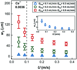 | ||
| Fig. 8 The thickness of the annular film around the gas bubbles estimated by fitting the mathematical model of eqn (3) at different volumetric liquid flow rates and bubble speeds. Insert shows a magnified view of the thickness of the annular film for QOrg = 0.1 mL min−1, QAq = 0.3 mL min−1. (for Ca** see ESI† section 1). | ||
Based on the fitted values of w1 and w2, the overall mass transport coefficient of 1-hexene which accounts for both the mass transport across annular film and interfacial film in series, koverall (the whole term in bracket in eqn (3)) as well as the mass transport coefficient of 1-hexene (kL![[a with combining low line]](https://www.rsc.org/images/entities/i_char_0061_0332.gif) hex,int) and hydrogen (kL
hex,int) and hydrogen (kL![[a with combining low line]](https://www.rsc.org/images/entities/i_char_0061_0332.gif) H2,int) across the interfacial film (eqn (S5) in ESI†) were calculated at different operational conditions as depicted in Fig. 9a. Increasing QT at constant bubble flow speed decreased the overall 1-hexene mass transport coefficient, koverall. Since the thickness of interfacial film was nearly constant, the reduction in the overall 1-hexene mass transport coefficient was mainly due to thickening of the annular film; a two-time increment in QT resulted in a halving of the 1-hexene mass transport coefficient. In addition, increasing the bubble speed at constant volumetric liquid flow rate increased the overall 1-hexene mass transport coefficient due to thinner annular film and concomitantly higher mass transport rate.
H2,int) across the interfacial film (eqn (S5) in ESI†) were calculated at different operational conditions as depicted in Fig. 9a. Increasing QT at constant bubble flow speed decreased the overall 1-hexene mass transport coefficient, koverall. Since the thickness of interfacial film was nearly constant, the reduction in the overall 1-hexene mass transport coefficient was mainly due to thickening of the annular film; a two-time increment in QT resulted in a halving of the 1-hexene mass transport coefficient. In addition, increasing the bubble speed at constant volumetric liquid flow rate increased the overall 1-hexene mass transport coefficient due to thinner annular film and concomitantly higher mass transport rate.
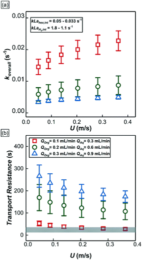 | ||
| Fig. 9 (a) The overall mass transport of 1-hexene at different experimental conditions. Insert shows the mass transport coefficient of 1-hexene and hydrogen across the interfacial film calculated from eqn (S5†). (b) 1-Hexene mass transport resistances of two distinct reactor regions under different experimental conditions. Scatter plots represent the 1-hexene mass transport resistances in the annular film region whereas the shaded grey area represents the 1-hexene mass transport resistance in the interfacial film region. | ||
From eqn (3), the individual mass transport coefficients of 1-hexene for annular and interfacial film regions were extracted and mass transport resistances were calculated for different QT and bubble speeds (Fig. 9b). The mass transport resistance is defined as the reciprocal of the mass transport coefficient. When QT = 0.4 mL min−1, the two organic regions (annular and interfacial film) had comparable 1-hexene mass transport resistances. On the other hand, when QT was increased beyond 0.4 mL min−1, the annular film offers significantly more transport resistance for 1-hexene due its thickening. It is worthwhile to note that there is no hydrogen mass transport resistance within the annular film due to negligible hydrogen consumption there. Consequently, based on the relative 1-hexene transport resistances within different reactor regions, two different reactor behaviors can be identified. In the first case, when the mass transport resistance across the annular film is either comparable or lower than that of interfacial film, which was observed when QT < 0.4 mL min−1, and when the reaction rate is dictated by the molecular transport rate of hydrogen, the reactor can be thought of as a series of individual and independent reactive ‘discs’ traversing the channel (Fig. 7b, top). The performance of such a reactor is independent of the number of the discs (and hence the bubble length) since the reaction is confined within the interfacial film. In the second case, when the mass transport resistance of the annular film is greater than that of the interfacial film, which was observed when QT is beyond 0.4 mL min−1, the reactor can be considered as an annulus of length LR (Fig. 7b, bottom) along which there are ‘sinks’ depleting the substrate along the inside surface of the annulus. The performance of such a reactor is directly related to bubble length since it determines the number of sinks along the annulus. Interestingly, in passing we note that this reactor behavior is analogous to chemical vapor deposition (CVD) reactors.42
3.4. Further scale-up of the mesoscale reactor
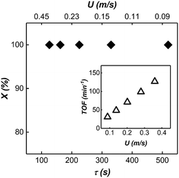
Based on the insight we gained from our reactor model, we further scaled up our mesoscale reactor by increasing the volumetric flow rate of the substrate, catalyst and the reactor length. To achieve high-volume continuous flow conditions, syringe pumps were replaced by peristaltic pumps. Capacitance-based hydraulic dampers21 were used to damp out the pressure fluctuations introduced by the peristaltic pumps, which can severely influence the multiphase flow stability (For the details of the experimental setup, see ESI† section 6 and movie M5). The reaction was conducted in a 45 m long 3.2 mm ID PTFE tube with 0.8 M (10% v/v) 1.2 mL min−1 organic substrate flow rate and 1 mM 3.6 mL min−1 catalyst flow rate. Due to the large volumetric flow rate, molecular transport in the annular film was the dominant factor dictating the observed kinetics. A large QT led to short bubble lengths, thus providing a large number of interfacial film regions for the reaction to take place. The large number of interfacial films along with longer residence time due to longer reactor length resulted in nearly complete conversion under all experimental conditions (see Fig. 10).3.5. Performance comparison of mesoreactor with similar gas–liquid–liquid contactors
In this section, the performance between the triphasic mesoreactor of this work is compared to its single channel and 8-fold parallelized millireactor and small-scale round-bottom flask counterparts (see Table 1). All flow reactors in this comparison have the same gas–liquid–liquid flow configuration and the same catalyst is used in all cases. The mass throughput of our mesoreactor was 150 times higher than its single milireactor channel counterpart at comparable residence time and conversion29 and ∼50 times higher than its 8-fold parallelized millireactor counterpart at comparable conversion and shorter residence time.21 In addition, when the same model reaction (hydrogenation of 1-hexene) was performed in a 50 mL round bottom flask under well stirred conditions (1200 RPM) with the same rhodium nanoparticle catalyst, significant improvement in reaction time and throughput was observed in our triphasic mesoreactor. A 120 g per day per channel throughput can be achieved with the operation conditions given in the previous section. The throughput of the single mesoscale channel can be further increased by more concentrated substrate and/or higher substrate flow rate with proper residence time. For example, if the reactor was operated with 1.2 mL min−1 organic phase flow rate and 50% v/v substrate concentration with 5–10 minutes of residence time a single mesoscale channel would produce 665 g hydrogenated product per day. Indeed, by simple 4–8 fold parallelization,21 3–5 kg of product per day can be produced, and this would be a realistic pilot scale reactor for pharmaceutical production with all the advantages highlighted in the introduction section.| Reactor | Residence time (min) | Conversion (%) | Substrate flow rate | Throughput (g per day) | TOF (min−1) |
|---|---|---|---|---|---|
| 50 mL round bottom flask29 | 60 | 100 | 5 mL 800 mM 1-hexene | 8.25 | 21 |
| 1 mm ID single triphasic29 milireactor channel | ∼1 | 82 | 10 μL min−1 800 mM 1-hexene | 0.8 | 634 |
| 1 mm ID 8-fold triphasic milireactor network21 | ∼8 | 80 | 8 × 20 μL min−1 100 mM nitrobenzene | 2.26 | 80 |
| Current work | ∼2 | 100 | 1.2 mL min−1 800 mM 1-hexene | 120 | 130 |
Summary and conclusion
We demonstrated a mesoscale triphasic (gas–liquid–liquid) reactor for fast, transition metal catalyzed gas–liquid reactions, which is capable of delivering kg per day productivity at the single channel level. Despite the increase in channel dimension, the mesoreactor is still able to intensify the mass transport whilst the retaining similar basic physics of operation with small scale systems. We also develop a complete reactor model incorporating the effect of various operating conditions for the model reaction – hydrogenation of 1-hexene in the presence of a colloidal rhodium nanoparticle catalyst. Moving from milliscale to mesoscale, we observe that annular film around gas bubbles acts as a reservoir for 1-hexene while in milliscale systems the reaction is confined to interfacial films with little or no role played by the annular films. Based on the insight we gain from the reactor model we further scaled up our system and achieved 150 times higher mass throughput compared to a single milliscale channel and ∼50 times the throughput of an 8-fold scaled out millireactor network at comparable residence time. Moreover, the throughput of the mesoreactor can be further increased by a very reasonable scale out by parallelization (4–8×), and catalyst recovery and recycle can be easily achieved due to compartmentalization of catalyst in a separate liquid phase. The analysis and design principles presented in this work are general, and the working principle of the mesoreactor can be extended to other metal catalyzed gas–liquid transformations. Our ongoing works include exploitation of new flow structures to further intensify the mass transport rate, understanding of residence time distribution (RTD) of organic phase, and implementation of our mesoreactor on different catalyst types as well as chemical reactions of relevance in pharmaceutical manufacturing.Nomenclature
![[a with combining low line]](https://www.rsc.org/images/entities/i_char_0061_0332.gif)
| Surface area to volume ratio |
| Bo | Bond number |
| C hex | Concentration of 1-hexene in decane |
| C H2,sat | Concentration of hydrogen in decane |
| C RhNP | Concentration of rhodium nanoparticle catalyst |
| D | Diffusivity |
| g | Gravitational acceleration |
| k overall | Overall mass transport coefficient of 1-hexene |
| L | Characteristic length |
| L B | Bubble length |
| L R | Reactor length |
| n | Number of the interfacial films per reactor length |
| Q Aq | Volumetric flow rate of aqueous phase |
| Q Gas | Volumetric flow rate of gas phase |
| Q Org | Volumetric flow rate of organic phase |
| Q T | Total liquid flow rate |
| TOF | Turnover frequency of catalyst |
| U | Flow speed |
| w 1 | Thickness of interfacial film |
| w 2 | Thickness of annular film |
Greek symbols
| γ | Interfacial tension |
| ρ | Density |
| τ | Bubble residence time |
Conflicts of interest
There are no conflicts to declare.Acknowledgements
The authors gratefully acknowledge funding from the GSK-EDB fund for Green and Sustainable manufacturing (GSM) and the Ministry of Education, Singapore.References
- B. Gutmann, D. Cantillo and C. O. Kappe, Angew. Chem., Int. Ed., 2015, 54, 6688–6728 CrossRef CAS PubMed.
- J. Yue, G. Chen, Q. Yuan, L. Luo and Y. Gonthier, Chem. Eng. Sci., 2007, 62, 2096–2108 CrossRef CAS.
- M. Liu, X. Zhu, R. Chen, Q. Liao, H. Feng and L. Li, Chem. Eng. J., 2016, 301, 35–41 CrossRef CAS.
- M. Brzozowski, M. O'Brien, S. V. Ley and A. Polyzos, Acc. Chem. Res., 2015, 48, 349–362 CrossRef CAS PubMed.
- K. K. Yeong, A. Gavriilidis, R. Zapf and V. Hessel, Catal. Today, 2003, 81, 641–651 CrossRef CAS.
- M. T. Rahman, T. Fukuyama, N. Kamata, M. Sato and I. Ryu, Chem. Commun., 2006, 2236–2238 RSC.
- C. P. Park and D.-P. Kim, J. Am. Chem. Soc., 2010, 132, 10102–10106 CrossRef CAS PubMed.
- Y. Önal, M. Lucas and P. Claus, Chem. Eng. Technol., 2005, 28, 972–978 CrossRef.
- A.-K. Liedtke, F. Bornette, R. Philippe and C. De Bellefon, Chem. Eng. J., 2013, 227, 174–181 CrossRef CAS.
- L. Vanoye, J. Wang, M. Pablos, R. g. Philippe, C. d. Bellefon and A. Favre-Réguillon, Org. Process Res. Dev., 2015, 20, 90–94 CrossRef.
- R. Chambers and R. H. Spink, Chem. Commun., 1999, 883–884 RSC.
- Y. Su, V. Hessel and T. Noël, AIChE J., 2015, 61, 2215–2227 CrossRef CAS.
- A. Woitalka, S. Kuhn and K. F. Jensen, Chem. Eng. Sci., 2014, 116, 1–8 CrossRef CAS.
- M. T. Kreutzer, F. Kapteijn, J. A. Moulijn and J. J. Heiszwolf, Chem. Eng. Sci., 2005, 60, 5895–5916 CrossRef CAS.
- R. D. Chambers, M. A. Fox, D. Holling, T. Nakano, T. Okazoe and G. Sandford, Lab Chip, 2005, 5, 191–198 RSC.
- Y. Wada, M. A. Schmidt and K. F. Jensen, Ind. Eng. Chem. Res., 2006, 45, 8036–8042 CrossRef CAS.
- A. M. Nightingale, J. H. Bannock, S. H. Krishnadasan, F. T. O'Mahony, S. A. Haque, J. Sloan, C. Drury and R. McIntyre, J. Mater. Chem. A, 2013, 1, 4067–4076 RSC.
- A. Nagaki, K. Hirose, O. Tonomura, S. Taniguchi, T. Taga, S. Hasebe, N. Ishizuka and J.-i. Yoshida, Org. Process Res. Dev., 2016, 20, 687–691 CrossRef CAS.
- Y. Su, K. Kuijpers, V. Hessel and T. Noël, React. Chem. Eng., 2016, 1, 73–81 RSC.
- M. Al-Rawashdeh, J. Zalucky, C. Muller, T. Nijhuis, V. Hessel and J. Schouten, Ind. Eng. Chem. Res., 2013, 52, 11516–11526 CrossRef CAS.
- S. K. Yap, W. K. Wong, N. X. Y. Ng and S. A. Khan, Chem. Eng. Sci., 2017, 169, 117–127 CrossRef CAS.
- R. Schenk, V. Hessel, C. Hofmann, J. Kiss, H. Löwe and A. Ziogas, Chem. Eng. J., 2004, 101, 421–429 CrossRef CAS.
- S. G. Newman and K. F. Jensen, Green Chem., 2013, 15, 1456–1472 RSC.
- M. Saber, J. Commenge and L. Falk, Chem. Eng. Sci., 2010, 65, 372–379 CrossRef CAS.
- M. Al-Rawashdeh, L. Fluitsma, T. Nijhuis, E. Rebrov, V. Hessel and J. Schouten, Chem. Eng. J., 2012, 181, 549–556 CrossRef.
- M. m. Al-Rawashdeh, X. Nijhuis, E. V. Rebrov, V. Hessel and J. C. Schouten, AIChE J., 2012, 58, 3482–3493 CrossRef CAS.
- N. de Mas, A. Günther, T. Kraus, M. A. Schmidt and K. F. Jensen, Ind. Eng. Chem. Res., 2005, 44, 8997–9013 CrossRef CAS.
- S. K. Yap, Y. Yuan, L. Zheng, W. K. Wong, J. Zhang, N. Yan and S. A. Khan, Green Chem., 2014, 16, 4654–4658 RSC.
- S. Yap, Y. Yuan, L. Zheng, W. Wong, N. Yan and S. Khan, J. Flow Chem., 2014, 4, 200–205 CrossRef.
- X.-d. Mu, D. G. Evans and Y. Kou, Catal. Lett., 2004, 97, 151–154 CrossRef CAS.
- J. J. Bakker, M. M. Zieverink, R. W. Reintjens, F. Kapteijn, J. A. Moulijn and M. T. Kreutzer, ChemCatChem, 2011, 3, 1155–1157 CrossRef CAS PubMed.
- P.-G. De Gennes, F. Brochard-Wyart and D. Quéré, Capillarity and wetting phenomena: drops, bubbles, pearls, waves, Springer Science & Business Media, 2013 Search PubMed.
- S. A. Khan and S. Duraiswamy, Lab Chip, 2009, 9, 1840–1842 RSC.
- K. J. Stebe, S. Y. Lin and C. Maldarelli, Phys. Fluids A, 1991, 3, 3–20 CrossRef CAS.
- J. N. Connor and R. G. Horn, Faraday Discuss., 2003, 123, 193–206 RSC.
- G. Barnocky and R. Davis, Int. J. Multiphase Flow, 1989, 15, 627–638 CrossRef CAS.
- B. M. Jose and T. Cubaud, RSC Adv., 2014, 4, 14962–14970 RSC.
- J. Campelo, A. Garcia, D. Luna and J. Marinas, Appl. Catal., 1982, 3, 315–325 CrossRef CAS.
- R. Madon, J. O'connell and M. Boudart, AIChE J., 1978, 24, 904–911 CrossRef CAS.
- P. Aussillous and D. Quéré, Phys. Fluids, 2000, 12, 2367–2371 CrossRef CAS.
- Y. Han and N. Shikazono, Int. J. Heat Fluid Flow, 2010, 31, 630–639 CrossRef CAS.
- M. L. Hitchman and K. F. Jensen, Chemical vapor deposition: principles and applications, Elsevier, 1993 Search PubMed.
Footnote |
| † Electronic supplementary information (ESI) available. See DOI: 10.1039/c9re00150f |
| This journal is © The Royal Society of Chemistry 2019 |


