DOI:
10.1039/D5TC03417E
(Paper)
J. Mater. Chem. C, 2026, Advance Article
Optimizing carbon-nanotube-driven polyhedral Cu2Mn3O8 structures for hybrid supercapacitors: unveiling strategies for enhanced electrochemical efficiency
Received
13th September 2025
, Accepted 4th January 2026
First published on 8th January 2026
Abstract
Driven by the intensifying global energy crisis, significant efforts have been focused on designing advanced nanostructured electrode materials that are capable of delivering both energy and power output simultaneously while ensuring optimized diffusion dynamics. Herein, a rationally engineered Cu2Mn3O8 (CMO) and its nanocomposites with 3%, 6%, and 9% carbon nanotubes (CNTs) (CMO-1, CMO-2, and CMO-3, respectively) were prepared via a cost-effective synthesis method. Quasi-rectangular, polyhedral structures were revealed via electron microscopy. A hybrid charge-storage mechanism was observed via voltammetric analysis combined with insights from Dunn's model. Galvanostatic charge–discharge testing revealed that CMO-2 delivered a specific capacity of 954.25 C g−1 at 11.76 A g−1, accompanied by an excellent energy density of 66.26 Wh kg−1 and power density of 2941.17 W kg−1. Notably, the electrode retained 99% of its initial capacity after 3000 cycles, confirming excellent durability. Galvanostatic intermittent titration technique measurements further estimated a diffusion coefficient of ∼4.96 × 10⁻¹⁵ m2 s−1 for the optimized sample, highlighting efficient ion transport through the electrode material. Electrochemical impedance spectroscopy revealed a low solution resistance of 0.91 Ω, high conductivity of 0.099 S cm−1, and a short relaxation time of 0.082 s. The observed agglomeration of CNTs in CMO-3 reduced the ion diffusion coefficient, highlighting a critical consideration for future researchers in optimizing material design. Collectively, these results position CMO-2 as a highly attractive electrode material for future hybrid supercapacitors.
1. Introduction
Efficient energy storage has become an important priority worldwide in the context of rapid scientific advancement, rising energy demands, and the ongoing climate crisis. Although fossil fuels still dominate global energy frameworks owing to their high energy output, their combustion generates harmful emissions that accelerate environmental degradation and hinder the transition to renewable energy sources.1,2 Moreover, population growth and the progressive depletion of natural reserves have further escalated the demand to adopt clean and sustainable alternatives such as wind and solar power.3 However, these renewable sources are inherently intermittent, as wind energy is dependent on weather conditions and solar power is ineffective during cloudy weather or at night.4 To address these challenges, significant research efforts have been directed toward developing energy storage systems (ESSs) capable of efficiently storing energy and delivering it reliably on demand. Conventional ESS technologies, including lithium-ion, sodium-ion, and metal–air batteries, as well as fuel cells, offer advantages such as high energy density (Ed) and operational versatility. Nevertheless, their practical deployment is limited by sluggish charge–discharge kinetics, relatively short lifespans, environmental concerns, and high production costs.5 Supercapacitors (SCs) have attracted growing attention as next-generation energy storage devices. Benefiting from advances in nanotechnology, SCs offer several superior features compared to conventional batteries, including high power density (Pd), fast charge–discharge capability, long cyclic stability, cost-effectiveness, and environmentally benign operation. These attributes make SCs highly attractive for applications requiring rapid energy delivery, extended durability, and minimal environmental impact, thereby positioning them as a promising solution in the evolving energy storage domain.6,7
SCs are categorized as electric double layer capacitors (EDLCs), pseudo capacitors (PCs), and hybrid capacitors (HCs) based on their electrochemical (EC) charge storage mechanism.8,9 An EDLC utilizes non-faradaic ion adsorption at the electrode–electrolyte (E/E) interface and offers remarkable cycling stability but suffers from low specific capacitance (Cs).10 The PCs, in contrast, rely on fast and reversible faradaic redox reactions, providing higher Cs but often at the expense of conductivity and long-term durability.11,12 The HCs integrate carbon-based EDLC materials with faradaic-active components, combining the high Pd and cyclic life of EDLCs with the remarkable Ed of PCs, thereby achieving balanced performance with improved stability and charge storage.13
The inherently limited Ed of SCs constrains their widespread applicability. Therefore, the development of efficient electrode materials remains crucial for enhancing EC performance.14 Extensive efforts have focused on diverse electrode classes, including carbon-based materials, transition metal oxides (TMOs), transition-metal sulfides, and conducting polymers.15–19 Among TMOs, CuO and NiO are particularly attractive, owing to their high theoretical capacities, rich redox activity, environmental benignity, and cost-effectiveness. However, their practical use is limited by intrinsically low electrical conductivity and structural instability during charging and discharging.20,21 To address these drawbacks, mixed transition metal oxides (MTMOs) have emerged as promising candidates, as the incorporation of divalent (Cu2+, Ni2+, and Fe2+) and trivalent (Mn3+, Al3+, Co3+, and Ti3+) cations facilitates multiple redox transitions, enhances electrical pathways, and improves structural robustness.22 In particular, Mn-based MTMOs are compelling because of their lower toxicity, natural abundance, tunable oxidation states, and affordability. Nevertheless, their experimentally achieved capacitance remains far below the theoretical limit, primarily due to poor electron transport.23,24 Among MTMOs, CMO has attracted considerable interest, as the coexistence of multiple Cu and Mn valence states enables efficient and reversible redox reactions. Despite these advantages, CMO suffers from moderate conductivity and particle agglomeration, which restricts charge transport and reduces the accessible active surface area. To overcome these limitations, incorporating highly conductive CNTs is a viable strategy. In particular, CNTs offer excellent electrical conductivity, high aspect ratio, mechanical robustness, and an interconnected 3D network, making them superior to other carbonaceous materials. Thus, the integration of CMO with CNTs is expected to enhance electron mobility, modify the electronic structure, improve structural integrity, and ultimately deliver outstanding EC performance. Further, these two develop interfacial interaction between the working electrode and the electrolyte, enhancing the overall performance of the system.25,26
Several studies have explored CuMn2O4-based electrode materials to enhance the performance of SCs. Deva et al. synthesized CuMn2O4 utilizing a sol–gel method (auto-combustion), achieving a Cs of 822.02 F g−1 at a current density (Cd) of 1 A g−1, with 91% coulombic efficiency (CE) retained after completing 5000 cycles.27 A solvothermal technique was utilized by Kumar et al. to synthesize CuMn2O4 nanoparticles, achieving a Cs of 520.5 F g−1 at a scan rate (SR) of 10 mV s−1. Further, the electrode material exhibited an excellent Cs of 578.01 F g−1 at 0.5 A g−1 and 98% capacitance retention after prolonged cycling.28 Zhang et al. employed the sol–gel technique to prepare a CuMn2O4//rGO composite, which exhibited a Cs of 342.12 F g−1 at 1 A g−1, outperforming CuMn2O4 and demonstrating enhanced rate capability.29 Beknalker et al. synthesized a CuMn2O4@MXene composite via the hydrothermal method, which delivered an enhanced areal capacitance of 629 mF cm−2 at 4 mA cm−2. The corresponding asymmetric device achieved a Cs of 496 mF cm−2 at 6 mA cm−2 and Pd of 1.5 mW cm−2.30 More recently, Alrowaily et al. reported the synthesis of CuMn2O4, MoS2, and CuMn2O4/MoS2 composites via a hydrothermal route, where the CuMn2O4/MoS2 electrode exhibited an outstanding Cs of 1244 F g−1 at Cd of 1 A g−1, with 25 Wh kg−1 Ed and 93% capacitance retention in assembled SC devices.31
Although CuMn2O4 and CuMnO2 have been investigated for energy storage applications, thus far, the synthesis and utilization of CMO in SC applications have not been reported. In this work, CMO was synthesized via a hydrothermal strategy, and nanocomposites were further prepared by incorporating 3, 6, and 9 wt% CNTs through a solvothermal approach. The rational integration of CNTs into the CMO matrix was designed to mitigate the intrinsic limitations of Cu-Mn-based TMOs, including moderate conductivity and agglomeration, while synergistically enhancing electron transport, ion diffusion, and structural stability. This compositional tuning strategy was expected to achieve high Ed, optimize ion-electron transfer kinetics, and unlock the redox activity of multivalent Cu and Mn centers. Overall, this study not only addresses the long-standing challenges associated with Cu–Mn oxide electrodes but also provides new insight into the design of high-performance hybrid electrode materials for next-generation SCs.
2. Experimental
2.1. Synthesis of CMO
CMO was synthesized using a hydrothermal approach to investigate EC features while controlling its morphology. All chemical precursors, including copper–nitrate hexahydrate (Cu(NO3)2·6H2O, 98% purity), manganese–nitrate nonahydrate (Mn(NO3)2·9H2O, 98% purity), urea (CO(NH2)2, 99% purity), and ammonium fluoride (NH4F, 97% purity), were procured from a reputable supplier (Sigma-Aldrich) and utilized directly without additional purification.
Stoichiometric quantities of precursors were dissolved in 40 mL of distilled water (DIW). The solution was continuously stirred magnetically to ensure initial homogenization and then ultrasonicated to promote effective exfoliation, reduce particle clustering, and minimize agglomeration. Following ultrasonication, the mixture was magnetically stirred at 250 rpm for 30 min to ensure complete homogeneity. The precursor solution was then transferred to a Teflon-lined stainless-steel reactor and subjected to hydrothermal treatment at 180 °C for 16 h. The selection of specific temperature and duration was optimized via initial trials to obtain pure CMO with uniform morphology. The optimized conditions present a balanced compromise between controlled particle growth and sufficient crystallinity. After the reaction, the autoclave was allowed to cool to room temperature. The resulting precipitates were collected and washed repeatedly with ethanol and DIW to eliminate impurities and unreacted chemicals. The obtained precipitates were dried under suitable conditions and subsequently calcined at 550 °C for 4 h to enhance crystallinity and obtain the final powder.
2.2. Synthesis of CMO/CNT nanocomposites
A facile solvothermal technique was employed to synthesize CMO-1, CMO-2, and CMO-3 nanocomposites. Precisely-measured amounts of CMO and CNTs were suspended in 30 mL of ethanol and subjected to ultrasonication for 30 min to attain uniform dispersion. The suspension was then magnetically stirred continuously at 250 rpm for an additional 30 min to ensure homogeneity. The mixture was subsequently transferred to a Teflon-coated stainless-steel reactor and thermally treated at 180 °C for 3 h. Following the reaction, the obtained precipitates were thoroughly rinsed sequentially with ethanol and DIW by centrifugation to eliminate residual impurities. Finally, the purified nanocomposites were dried on a hot plate, yielding the CMO/CNTs materials, which were later used for electrode fabrication.
2.3. Electrode fabrication
Nickel foam (NF) was cut into 1 × 1.5 cm2 pieces and subjected to surface etching to improve adhesion of the active material. The NF was etched by immersing in an acidic solution containing 30% hydrochloric acid and 70% DIW, followed by sonication for 1 h. A binder solution was formulated by dissolving 3 mg of polyvinylidene fluoride in 15 mL of dimethylformamide under continuous stirring until complete dissolution. Subsequently, a homogeneous slurry was prepared by mixing the binder, active material, and activated carbon (AC) in a 10![[thin space (1/6-em)]](https://www.rsc.org/images/entities/char_2009.gif) :85:5 ratio, respectively. The slurry was evenly deposited onto the etched NF with a pipette gun and dehydrated at 70 °C. Fig. 1 illustrates the synthesis of active materials and the fabrication of electrodes.
:85:5 ratio, respectively. The slurry was evenly deposited onto the etched NF with a pipette gun and dehydrated at 70 °C. Fig. 1 illustrates the synthesis of active materials and the fabrication of electrodes.
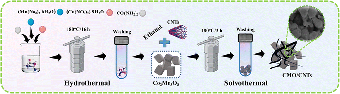 |
| | Fig. 1 Schematic illustration of the synthesis of the CMO and CNT-incorporated composites through a hydrothermal process, followed by a solvothermal process. | |
2.4. Characterization techniques
To comprehensively investigate the properties of the synthesized nanomaterials, a series of structural, morphological, elemental, and EC characterizations was employed. Structural characterization was conducted utilizing X-ray diffraction analysis (XRD) (Rigaku SmartLab SE XRD) equipped with a Cu-Kα radiation source (λ = 1.5406 Å) to confirm the crystalline phase and purity of the samples. The surface morphology and particle size distribution were analyzed utilizing a Nova Nano SEM-450 field-emission scanning electron microscope (SEM). Insightful information regarding the nanostructural features was obtained through transmission electron microscopy (TEM). Compositional analysis and uniformity were verified through energy-dispersive X-ray spectroscopy (EDX) using an integrated Oxford instrument setup. The EC performance was systematically investigated using a Corrtest CS350M workstation (version 6.8) in a conventional three-electrode setup, with a platinum wire and Ag/AgCl serving as the counter and reference electrodes, respectively, and 1 M KOH solution as the electrolyte. Cyclic voltammetry (CV), galvanostatic charge–discharge (GCD), galvanostatic intermittent titration technique (GITT), and electrochemical impedance spectroscopy (EIS) were conducted to evaluate the charge storage behavior, rate capability, and overall EC performance of the electrodes.
3. Results and discussion
3.1. X-ray diffraction analysis
XRD was performed to analyze the crystal structure of the prepared samples (CMO, CMO-1, CMO-2, and CMO-3).32 The XRD patterns, recorded in the 2θ range of 15°–70° depicted in Fig. 2(a), exhibited distinct diffraction peaks at 18.24°, 28.84°, 31.68°, 32.42°, 37.12°, 37.93°, 43.39°, 53.35°, 58.28°, and 59.68°, which correspond to the (110), (201), (020), (310), (220), (400), (221), (−131), (−331) and (402) planes, respectively. These hkl planes are well consistent with the ICSD reference # 00-026-0537, confirming the monoclinic structure of CMO. The incorporation of CNTs did not noticeably change the diffraction peak positions, indicating that the CMO lattice structure remained intact. The sharp, well-defined reflections further affirmed the high crystallinity of all samples, a desirable attribute for improved EC performance. Moreover, a distinct peak at a 2θ value of 26.11°, marked in Fig. 2(a), was indexed to the carbon phase, consistent with the standard reference pattern ICSD 00-026-1076, confirming the successful integration of CNTs. The average crystalline size was estimated via the Scherrer equation, eqn (1).33| | |
D = Kλ/βcosθ
| (1) |
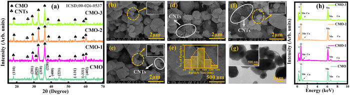 |
| | Fig. 2 (a) XRD patterns of pristine CMO and the CNT-incorporated CMO-1, CMO-2, and CMO-3 composites, (b)–(f) SEM micrographs of the synthesized samples at different magnifications, (g) TEM analysis of CMO-2, and (h) EDX spectra validating the elemental composition of the prepared samples. | |
The calculated crystallite sizes for CMO, CMO-1, CMO-2, and CMO-3 were 18.79, 17.88, 18.40, and 18.78 nm, respectively. These results confirm that CNT integration preserved the structural stability of the CMO phase while maintaining high crystallinity throughout all compositions.
3.2. Morphological analysis
SEM analysis was performed to examine the structural morphology, particle dimensions, and microstructural features of all the nanomaterials.34 Fig. 2(b–e) shows the SEM images of all the prepared samples. Fig. 2(b) displays polyhedral and quasi-spherical particles forming an agglomerated network. The microstructure comprised a heterogeneous mix of small and large particles, ranging in size from nanometers to micrometers. A distinctly developed porous framework with pronounced grain boundaries and interparticle voids was evident, indicating a hierarchically porous architecture. Such structural porosity, coupled with controlled particle size distribution, is beneficial for rapid EC kinetics, thereby enhancing both Ed and Pd.35
SEM images of CNT-incorporated samples, as presented in Fig. 2(b–f), confirmed the successful incorporation of CNTs into the CMO matrix. The CNTs are uniformly dispersed and anchored onto multifaceted CMO particles, forming a three-dimensional conductive network, facilitating superior electrical conductivity and efficient ion diffusion pathways. Notably, CMO-2, as presented in Fig. 2(d and e), exhibited the most favorable morphology among all samples, where the optimal CNT loading created an extensive conductive network without compromising active site accessibility. Further, Fig. 2(e) shows the histogram of the CMO-2 composite revealing a particle size distribution, which is in the range of micrometers. In contrast, CMO-3, as shown in Fig. 2(f), displayed CNT agglomeration, forming dense clusters that particularly covered the CMO surface. Such excessive CNT contents block electroactive sites and hinder ion diffusion, ultimately leading to reduced EC efficiency. These types of agglomerations can be minimized via different strategies, like prolonged stirring and sonication or solvent treatment methods.
In addition, Fig. 2(g) illustrates the TEM images of CMO-2, representing well-defined polyhedral particles at 1 µm and 500 nm magnification. These particles are uniformly interconnected with minimal agglomeration and sharp edges, consistent with the irregular microstructure morphology observed in SEM images. CMO-2 exhibits tubular structures, which correspond to the presence of CNTs within the material. Notably, the maximum nanoparticles were measured within the size range of micrometers, which correlates with the SEM analysis and is beneficial for ion transport. This ion transport promotes EC efficiency, underscoring the suitability of these materials for energy storage applications.
3.3. Compositional analysis
EDX analysis was performed to determine the elemental composition and spatial distribution of the samples.36 Fig. 2(h) illustrates the EDX spectra of pure CMO, CMO-1, CMO-2, and CMO-3 samples. For CMO, prominent peaks corresponding to Mn, Cu, and O confirmed the successful formation of the target phase. In contrast, the EDX spectra of CNT-integrated samples revealed characteristic C peaks, validating the successful integration of CNTs into the CMO matrix. A gradual increase in the C peak intensity with CNT contents further confirmed the controlled integration of CNTs. The presence of Au peaks in all samples corresponded to a gold coating applied during sample preparation to improve conductivity. Importantly, no extraneous peaks were detected, signifying the absence of any impurities and attesting to the high chemical purity and precise compositional control of the synthesized nanocomposites.
3.4. Voltammetry study
CV is a fundamental EC technique that provides insights into charge storage mechanisms by measuring the current response to applied potential sweeps.37,38 In this study, CV analysis was performed using 1 M KOH electrolyte, as shown in Fig. 3(a), within a stable potential window ranging from 0 to 0.5 V. Fig. 3(b–f) depicts the CV profiles of CMO and CMO/CNT composites (CMO-1, CMO-2, and CMO-3) at SRs ranging from 2.5 to 15 mV s−1. The activation potential of all the synthesized samples was detected in the range of 0.26 to 0.31 V. Fig. 3(b) illustrates the CV voltammogram of CMO, where distinct redox peaks are clearly visible in each cycle, confirming significant pseudocapacitive behavior, originating from a reversible faradaic redox reaction.39,40 In addition, a linear region at the start of the forward sweep and reverse sweep indicates the presence of non-faradaic contributions.41 The overall CV curve thus reveals a hybrid charge storage behavior.
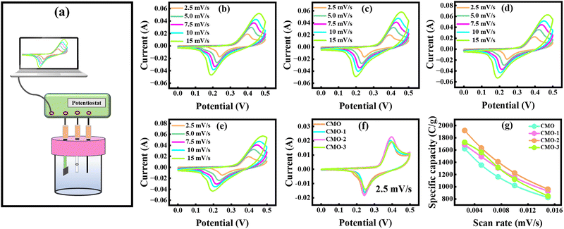 |
| | Fig. 3 (a) Schematic of the three-electrode system, (b)–(e) CV profiles of CMO, CMO-1, CMO-2, and CMO-3 at various scan rates, (f) comparative CV curves of all samples at a scan rate of 2.5 mV s−1, and (g) variation of specific capacity with scan rate for all the electrodes. | |
At elevated SRs, the anodic peaks shifted towards higher potentials and cathodic peaks shifted more towards negative potentials, which is attributed to polarization effects and restricted ion diffusion.42,43 Nevertheless, the CV curves retained their shape, demonstrating excellent rate capability and kinetic reversibility.44,45 However, at elevated SRs, broadening of the CV loops was observed as shown in Fig. 3(b), which can be attributed to the formation of resistive layers and hindered ion penetration into the inner channels of the materials. The CNT-incorporated composites exhibited similar trends but with markedly enhanced EC performance. For instance, the CV voltammogram of CMO-1, as depicted in Fig. 3(c), demonstrated an increase in the CV loop area as compared to CMO, attributed to the enhanced surface area and conductive network provided by CNTs, leading to the high charge storage capability and substantially improved EC response.46 CMO-2 exhibited the highest integrated area among all synthesized samples, indicating better electrolyte access and a strong synergetic interaction between CMO and moderate concentration of CNTs. In contrast, the cyclic voltammogram of CMO-3, as shown in Fig. 3(e), exhibited a reduced CV loop area, likely due to the aggregation of CNTs at higher loading, which blocked active sites and disrupted electron pathways, thereby limiting conductivity and charge storage capability.47 The specific capacity (Qs) evaluated from the cyclic voltammogram provides a quantitative measure of EC performance and was calculated using eqn (2).
| |
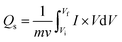 | (2) |
Here, the integral part corresponds to the total area enclosed by the CV curves, v represents the SR, V corresponds to the applied potential, and m represents the active mass of material. The maximum Qs value of 1919.09 C g−1 was obtained for the CMO-2 electrode at a SR of 2.5 mV s−1, the highest among all other electrodes. The higher Qs at lower SRs arise from enhanced ion diffusion, which enables complete utilization of active sites, while the decrease in Qs at higher SRs reflects the limited ion accessibility within shorter time intervals.48 Fig. 3(f) compares the redox behavior of all the synthesized samples at 2.5 mV s−1, highlighting the significant improvement in Qs achieved by incorporating 6% CNTs. Furthermore, Fig. 3(g) illustrates the relationship between SRs and Qs for all electrodes, with the results summarized in Table 1. Overall, CV analysis confirms that optimal CNTs (CMO-2) provide superior Qs rate capability owing to synergistic pseudocapacitive contributions and efficient ion transport pathways.
Table 1 Specific capacity of CMO, CMO-1, CMO-2, and CMO-3 electrodes at different scan rates
| Scan rates (mV s−1) |
CMO (C g−1) |
CMO-1 (C g−1) |
CMO-2 (C g−1) |
CMO-3 (C g−1) |
| 2.5 |
1623.57 |
1685.81 |
1919.09 |
1724.49 |
| 5 |
1356.18 |
1491.17 |
1633.26 |
1561.25 |
| 7.5 |
1163.22 |
1309.95 |
1406.96 |
1316.65 |
| 10 |
1020.04 |
1153.611 |
1225.02 |
1124.40 |
| 15 |
825.11 |
928.26 |
959.93 |
849.63 |
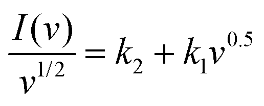
3.4.1. Theoretical analysis using Dunn's model. A theoretical model was employed to confirm the EC behavior of the synthesized electrodes. The CV plots were analyzed to predict whether the charge storage process was predominantly diffusive-controlled or capacitive-controlled by examining the current response as a function of SRs (2.5–15 mV s−1), as shown in Fig. 3(b–e). The mechanism was further understood by calculating the b-value from the analysis. To further understand the mechanism, both the power-law relationship and Dunn's model quantify the contributions from capacitive and diffusive processes. The power law expresses the relationship between peak current (Ip) and scan rate (v) as in eqn (3) and (4).| | |
log(Ip) = log(a) + blog(v)
| (4) |
Here, a and b are empirical parameters. The slope of the log(Ip) vs. log(v) plot yields the b-value, which reveals the charge-storage mechanism.49–51 A b-value of 1.0 indicates EDLC nature, whereas a b-value of 0.5 signifies diffusive nature; intermediate b-values suggest a hybrid charge storage mechanism.52 As shown by the linear fittings in Fig. 4(a–d), the calculated b-values for CMO, CMO-I, CMO-2, and CMO-3 are 0.67, 0.86, 0.88, and 0.86, respectively. These values indicate that the charge-storage behavior of all samples is governed by the predominantly hybrid EC mechanism, involving contributions from both diffusion-controlled and surface-controlled processes. The relatively higher b-value indicated that CMO-2 provides a stronger non-faradaic contribution, which underpins its remarkable energy storage capability.53 To further decouple the contributions, Dunn's model was applied, which separates the current into diffusive and capacitive components, as given in eqn (5)–(7).
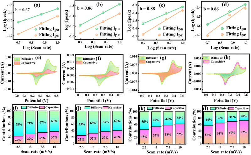 |
| | Fig. 4 (a)–(d) Linear fitting analysis of CMO, CMO-1, CMO-2, and CMO-3 for theoretical evaluation of the charge storage mechanism, (e)–(h) CV plots emphasized the contribution of diffusive and capacitive currents at a scan rate of 2.5 mV s−1, and (i)–(l) Dunn model-based analysis of capacitive and diffusive percentage contributions at varying scan rates for all the electrodes. | |
By rearranging eqn (6).
| |
 | (7) |
Here, k1 and k2 are constants related to diffusive and capacitive contributions, respectively.54 By plotting  vs. v0.5, the slope and intercept yield the respective fractions of capacitive and diffusive currents. The percentage of capacitive and diffusive contributions at a fix scan rate of 2.5 mV s−1 is depicted in Fig. 4(e–h). The bar charts, as illustrated in Fig. 4(i–l), demonstrate the percentage contributions of all electrode materials (CMO, CMO-1, CMO-2, and CMO-3). At 2.5 mV s−1, CMO exhibited a diffusive contribution of approximately 78% along with a capacitive contribution of about 22%. In contrast, CMO-1, CMO-2, and CMO-3 showed diffusive contributions of 75%, 55%, and 44%, with corresponding capacitive contributions of 25%, 45% and 56%, respectively. The pronounced capacitive contribution in CMO-2 underscores the dominance of non-faradaic processes in governing its charge storage kinetics. Furthermore, Fig. 4(i-l) shows that with increasing SR, capacitive contributions increased across all samples, reflecting the prevalence of surface-controlled non-faradaic processes at higher rates. Overall, the theoretical analysis confirmed the hybrid charge storage nature of the synthesized electrodes.
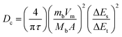
3.5. Galvanostatic charge discharge analysis
The GCD technique was employed to assess the charge storage behavior of the synthesized electrodes, including Qs, Ed, Pd, and cyclic stability.55 The GCD profiles for all electrodes were recorded at different Cd values, deliberately restricted compared to CV to suppress hydrogen evolution and ensure reliable measurements.56 Fig. 5(a–d) presents the GCD profiles of CMO, and CNT-incorporated samples at different Cd values of 11.76, 17.65, 23.53, 29.41, and 35.29 A g−1. All electrodes exhibited quasi-triangular GCD profiles with distinct plateaus, consistent with the hybrid charge storage behavior observed in CV. These plateaus correspond to redox peaks, confirming the dominance of faradaic redox reactions in the charge storage process.57,58 The GCD profiles of pristine CMO were observed at Cd values of 11.76–35.29 A g−1. As depicted in Fig. 5(a), the area under the GCD curve is proportional to the charge–discharge time, providing insight into the electrode EC performance. The longest discharge duration was observed at 11.76 A g−1, corresponding to the maximum Qs, while at 35.29 A g−1, a shorter discharge time was ascribed to diffusion-limited charge kinetics and hindered ion transports at higher Cd.59,60 In comparison, CMO-1, as depicted in Fig. 5(b), exhibited a progressively enlarged discharge time relative to pure CMO, demonstrating improved capacity owing to the synergistic effect of CNTs and Cu–Mn active sites. CMO-2, as shown in Fig. 5(c), exhibited further extended charge discharge time, confirming remarkable EC kinetics and higher utilization of active material. This improvement can be attributed to moderate CNT contents, which promoted the well-interconnected conductive networks, facilitating fast ion transport. Conversely, CMO-3, as shown in Fig. 5(d), demonstrated a reduction in discharge time, likely due to the aggregation of CNTs at higher loading, which blocked ion pathways and hindered access to the electroactive sites. Fig. 5(e) shows the charge–discharge curves at 11.76 A g−1 for all the samples. The Qs were calculated by employing eqn (8).| |
 | (8) |
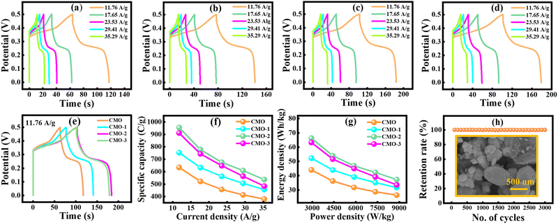 |
| | Fig. 5 (a)–(d) GCD profiles of CMO, CMO-1, CMO-2, and CMO-3 at different current densities, (e) comparison of all the electrodes at 11.76 A g−1, (f) variation of specific capacity with current density, (g) Ragone plot for all fabricated electrodes, and (h) capacity retention of CMO-2 up to 3000 cycles along with post-cycling FESEM analysis. | |
Here, Δt (s) is the discharging time, I (mA) is the applied current, and m (mg) is the active mass deposited on the electrode materials. Among all the electrodes, CMO-2 delivered the highest Qs of 954.25 C g−1 at 11.76 A g−1, with a discharge duration of 81.11 s, clearly outperforming other samples. A progressive decline in Cs with an increasing Cd was observed for all the synthesized electrodes depicted in Fig. 5(f). The Ed and Pd were calculated using eqn (9) and (10).
| |
 | (9) |
| |
 | (10) |
At 11.76 A g−1, CMO exhibited an Ed of 44.02 Wh kg−1 with a Pd of 2941.17 W kg−1, whereas CMO-1 achieved 52.27 Wh kg−1 Ed. Remarkably, CMO-2 achieved an excellent Ed of 66.26 Wh kg−1, significantly higher than its counterparts. The calculated values of Qs, Ed, and Pd for all the samples at Cd of 11.76 A g−1 are presented in Table 2. The Ragone plots illustrated in Fig. 5(g) provide the trade-off between Ed and Pd, where CMO-2 consistently outperformed the other electrodes across all Cd. The calculated values of Qs, Ed, and Pd for all t prepared electrode materials are shown in Table 3.
Table 2 Specific capacity, energy density, and power density at the current density of 11.76 A g−1 for CMO, CMO-1, CMO-2, and CMO-3
| Sample |
Current density (A g−1) |
Discharge time (s) |
Specific capacity (C g−1) |
Energy density (Wh kg−1) |
Power density (W kg−1) |
| CMO |
11.76 |
53.89 |
634.02 |
44.02 |
2941.17 |
| CMO-1 |
11.76 |
63.98 |
652.73 |
52.27 |
2941.17 |
| CMO-2 |
11.76 |
81.11 |
954.25 |
66.26 |
2941.17 |
| CMO-3 |
11.76 |
77.42 |
910.88 |
63.25 |
2941.17 |
Table 3 Specific capacity, discharge time, energy density, and power density of CMO, CMO-1, CMO-2, and CMO-3 at different current densities from the GCD analysis
| Sample |
Current density (A g−1) |
Discharge time (s) |
Specific capacity (C g−1) |
Energy density (Wh kg−1) |
Power density (W kg−1) |
| CMO |
11.76 |
53.89 |
634.02 |
44.02 |
2941.17 |
| 17.64 |
29.58 |
522.12 |
36.26 |
4411.76 |
| 23.53 |
19.44 |
457.48 |
31.76 |
5882.35 |
| 29.41 |
14.06 |
413.74 |
28.73 |
7352.94 |
| 35.29 |
10.78 |
380.56 |
26.42 |
8823.52 |
| |
| CMO-1 |
11.76 |
63.98 |
752.73 |
52.27 |
2941.17 |
| 17.64 |
35.87 |
633 |
43.95 |
4411.76 |
| 23.53 |
23.92 |
562.84 |
39.08 |
5882.35 |
| 29.41 |
17.22 |
506.55 |
35.17 |
7352.94 |
| 35.29 |
12.93 |
456.58 |
31.7 |
8823.52 |
| |
| CMO-2 |
11.76 |
81.11 |
954.25 |
66.26 |
2941.17 |
| 17.64 |
44.06 |
777.65 |
54 |
4411.76 |
| 23.53 |
28.71 |
675.55 |
46.91 |
5882.35 |
| 29.41 |
20.71 |
609.18 |
42.3 |
7352.94 |
| 35.29 |
15.21 |
537.01 |
37.29 |
8823.52 |
| |
| CMO-3 |
11.76 |
77.42 |
910.88 |
63.25 |
2941.17 |
| 17.64 |
42.12 |
743.41 |
51.62 |
4411.76 |
| 23.53 |
27.55 |
648.24 |
45.01 |
5882.35 |
| 29.41 |
19.17 |
563.97 |
39.1 |
7352.94 |
| 35.29 |
13.7 |
483.56 |
33.58 |
8823.52 |
Long-term cyclic stability was further examined under repeated GCD cycling. As shown in Fig. 5(h), the CMO-2 electrode maintained 99% of its original Qs after completing 3000 consecutive cycles, signifying exceptional structural stability and EC durability. Additionally, the post-cycling SEM image (CMO-2) demonstrates a well-dispersed three-dimensional porous network, demonstrating minimal structural degradation after prolonged 3000 charge–discharge cycles, as shown in Fig. 5(h). These findings highlight the potential of the CMO-2 nanocomposite as an excellent electrode material for SC applications.
3.5.1. Galvanostatic intermittent titration technique. GITT is a powerful method to probe the diffusion dynamics and charge-transfer kinetics of electrode materials by evaluating the ion diffusion coefficient (Dc).61,62 The GITT measurements were carried out in a 2 M KOH electrolyte by applying a constant current pulse to the EC cell for a set duration, during which ions adsorb/desorb at the E/E interface. Following each pulse, the subsequent relaxation time and the corresponding potential response were recorded and used to evaluate Dc. Dc represents the rate of ion migration within the electrode during charge–discharge processes and can be calculated from Fick's law using eqn (11).| |
 | (11) |
Here, Dc is the diffusion constant in (m2 s−1), τ is the pulse duration (s), mb represents the active mass, Vm denotes the molar volume, and Mb corresponds to the molecular weight of the compound, A is the E/E interfacial area, and m is the electrode thickness. Moreover, ΔEs represents the steady state voltage amid an individual GITT pulse, and ΔEt is the total voltage change excluding IR drop.63 GITT data were recorded for all electrodes at a current of 1 mA, with a pulse duration of 600 s. Measurements were conducted at charging and discharging potentials of 0.4 V and 1.5 V, respectively. A quasi-steady state voltage response was obtained, as illustrated in Fig. 6(a–d). For pure CMO, the calculated Dc was 4.38 × 10⁻¹⁵ m2 s−1. The incorporation of 3% CNTs in CMO-1 enhanced ion transport, yielding a slightly higher Dcf 4.44 × 10⁻¹⁵ m2 s−1. CMO-2 exhibited a further increase, reaching 4.96 × 10⁻¹⁵ m2 s−1, attributed to the development of a well-interconnected conductive network at moderate CNT loading, which provided additional ion diffusion pathways. However, in CMO-3, excessive CNT incorporation caused agglomeration and blockage of active sites, leading to a reduction in Dc to 4.48 × 10⁻¹⁵ m2 s−1. Overall, the GITT analysis revealed that by moderate CNT loading, CMO-2 significantly enhanced ion diffusion dynamics, while both low and excessive CNTs concentrations yielded pronounced improvements. The variations in Dc across charging and discharging pulses also suggest excellent reversibility of Cu/Mn ion insertion and extraction, further confirming the superior EC kinetics of the CMO-2 electrode.
 |
| | Fig. 6 (a)–(d) GITT profiles of CMO, CMO-1, CMO-2, and CMO-3, highlighting ion diffusion kinetics at constant current pulses. | |
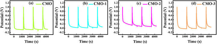
3.6. Electrochemical impedance spectroscopy
EIS serves as a versatile technique that provides detailed insights into EC processes at the E/E interface, particularly charge-transfer kinetics and interfacial interactions.64 EIS spectra, typically presented as Nyquist and Bode plots, were recorded at frequencies ranging from 10-2 to 105 Hz to probe the intrinsic EC and kinetic behavior of the synthesized electrodes. In the Nyquist spectrum, the real impedance (Z′) was plotted on the x-axis, while the imaginary part (Z″) was plotted on the y-axis.65,66 The extracted Nyquist spectra were fitted utilizing the Randle circuit model, as illustrated in Fig. 7(a–d). The Nyquist plot comprises three characteristic regions: (1) a high frequency intercept attributed to solution resistance (Rs), (2) a semicircle in the mid-frequency region attributed to charge-transfer resistance (Rct) related to Cu/Mn redox reaction at the E/E interface, (3) a low-frequency inclined line reflecting Warburg impedance, linked to ion diffusion into the electrode bulk.67,68 The extracted Nyquist plot yielded Rs values of 1.29, 1.04, 0.91, and 1.06 Ω for CMO, CMO-1, CMO-2, and CMO-3, respectively, as summarized in Table 4. Among all samples, CMO-2 exhibited the lowest Rs together with a reduced Rct (4.43 Ω), signifying superior charge-transfer kinetics and remarkable EC activity.
 |
| | Fig. 7 (a)–(d) Nyquist plots with fitted Randle circuits for CMO, CMO-1, CMO-2, and CMO-3, (e) combined Bode plot, and (f)–(h) variation in relaxation time, ionic conductivity, solution, and charge-transfer resistance. | |
Table 4 Values of elements for the corresponding fitted circuit, R1 = Rs, R2 = Rct, Q2 = constant phase elements, and W = Warburg diffusion element
| Sample |
R1 (Ω) |
R2 (Ω) |
Q2 (Fs(a-1)) |
W (Ω) |
| CMO |
1.29 |
6.92 |
0.010 |
2.52 |
| CMO-1 |
1.04 |
4.61 |
0.011 |
2.37 |
| CMO-2 |
0.91 |
4.43 |
0.016 |
2.10 |
| CMO-3 |
1.06 |
5.40 |
0.013 |
2.25 |
3.6.1. Bode plot analysis. The Bode plot presents complementary information by representing the logarithm of frequency against the negative phase angle. It allows assessment of the charge storage process and relaxation behavior. Ideally, capacitive electrodes exhibit a phase angle approaching 90° at lower frequencies, whereas pseudocapacitive contributions are generally observed near 45°.69,70 As illustrated in Fig. 7(e), the phase angles of all electrodes were dominated by pseudocapacitive behavior, consistent with CV results discussed earlier, indicating that the overall capacitance mainly arises from reversible faradaic redox reactions rather than purely double-layer effects.
3.6.2. Relaxation time. Relaxation time is another critical parameter in the evaluation of SCs, representing the minimum time required to discharge the stored energy.71 It can be calculated by employing eqn (12).| |
 | (12) |
Here, τ represents the relaxation time, and f denotes the characteristic frequency at which resistive and capacitive resonance co-exist. The calculated τ values for CMO, CMO-1, CMO-2, and CMO-3 were 0.103, 0.092, 0.082, and 0.099 s, respectively, as shown in Table 5. Fig. 7(f) shows the variation in the relaxation time relative to all the tested electrode materials. Notably, CMO-2 exhibited the shortest τ, suggesting faster ion transport kinetics and its ability to deliver stored energy rapidly during charging–discharging processes.
Table 5 Calculated values of relaxation time, conductivity, and diffusion coefficient
| Sample |
Frequency (Hz) |
Relaxation time (s) |
Conductivity (S cm−1) |
Diffusion coefficient (m2 s−1) |
| CMO |
1.59 |
0.103 |
0.069 |
4.38 × 10⁻¹⁵ |
| CMO-1 |
1.76 |
0.092 |
0.086 |
4.44 × 10⁻¹⁵ |
| CMO-2 |
1.84 |
0.082 |
0.099 |
4.96 × 10⁻¹⁵ |
| CMO-3 |
1.60 |
0.099 |
0.084 |
4.48 × 10⁻¹⁵ |
3.6.3. Ionic conductivity. Ionic conductivity represents the capability of an electrode material to support efficient ion transport, which directly governs its redox activity and EC performance. Elevated ionic conductivity improves ion mobility and intensifies redox reaction, thereby enabling a more efficient and effective charge storage process.72,73 Ionic conductivity of all the prepared samples was calculated using eqn (13), as shown below.| |
 | (13) |
Here, σ represents the ionic conductivity, L represents the thickness of the electrode material, A is the electrode area, and Rs represents solution resistance. The results presented in Table 5 show that CMO-2 exhibited the highest σ of 0.099 S cm−1, indicating minimal resistance to ion migration and enhanced EC reactivity. This improvement was attributed to the moderate incorporation of CNTs (6%), which effectively lowered both Rs and Rct, thereby establishing efficient ion-transport pathways and promoting fast charge transfer. Fig. 7(g) compares the ionic conductivity values of the synthesized electrodes, revealing that CMO-2 demonstrates superior σ among all samples. Furthermore, Fig. 7(h) illustrates the correlation between Rs and Rct, highlighting the comparative interfacial kinetics of the prepared electrodes. The overall comparative evaluation of the EC performance is summarized in Table 6.
Table 6 A comprehensive comparison of reported literature, synthesis strategies, and electrochemical performance parameters of related electrode materials
| Composition |
Method |
Cs |
Pd (W kg−1) |
Ed (Wh kg−1) |
Diffusion coefficient |
Cyclic stability |
Ref. |
| CuMn2O4 |
Sol–gel auto Combustion |
822 F g−1 at 1 A g−1 |
1125 |
18.2 |
N/A |
91.2% (10 k cycle) |
27 |
| CuMn2O4/Ti3C3 |
Hydrothermal |
577 F g−1 at 0.5 A g−1 |
N/A |
N/A |
N/A |
91.2% (10 k cycle) |
28 |
| CuMn2O4/rGO |
Sol–gel |
347 F g−1 at 1 A g−1 |
885.3 |
121.6 |
N/A |
75.5% (10 k cycle) |
29 |
| CuMn2O4/MoS4 |
Hydrothermal |
1244 F g−1 at 1 A g−1 |
198 |
27 |
N/A |
93.43% |
31 |
| NiMnO3/CNTs/PANI |
Hydrothermal |
1276 F g−1 at 0.5 A g−1 |
124.9 |
44.30 |
N/A |
84.6% (5 k cycle) |
45 |
| MnO2/CuO |
Hydrothermal |
279 F g−1 at 0.5 A g−1 |
N/A |
N/A |
N/A |
91.26% (5 k cycle) |
74 |
| PANI/CuMn2O4 |
Hydrothermal |
1181 F g−1 at 1 A g−1 |
N/A |
N/A |
N/A |
95% (5 k cycle) |
75 |
| MnCo2O4 |
Deposition |
290 F g−1 at 1 mV s−1 |
5200 |
10.4 |
N/A |
N/A |
76 |
| ZnCo2O4/CoMoO4 |
Hydrothermal |
1040 C g−1 at 1 A g−1 |
2700 |
87.3 |
N/A |
99% (8 k cycle) |
77 |
| CuMn3O8/6%CNTs |
Hydrothermal |
954.25 C g−1 at 11.76 A g−1 |
2941.17 |
66.26 |
4.96 × 10 -15 m2 s−1 |
99% (3 k cycle) |
Present work |
4. Conclusion
In summary, this investigation reports the successful synthesis of CMO and its composites, CMO-1, CMO-2, and CMO-3, by utilizing an eco-friendly hydrothermal route, followed by a solvothermal reaction. Structural analysis confirmed that the monoclinic phase of CMO was preserved, irrespective of the CNT content, while morphological studies revealed polyhedral, quasi-spherical particles. The uniform incorporation of the polyhedral particles was also verified through TEM images at magnifications of 1 µm and 500 nm. The EDS analysis confirmed the successful synthesis of CMO and the incorporation of CNTs into the CMO matrix, with no extraneous peaks, thereby confirming the purity of these materials. CV analysis confirmed the hybrid charge storage mechanism, while Dunn's model further demonstrated the coexistence of capacitive and diffusive contributions. Among all the synthesized materials, CMO-2 exhibited an excellent Qs of 954.25 C g−1 and Ed of 66.26 Wh kg−1 along with a Pd of 2941.17 W kg−1 at 11.76 A g−1. Moreover, the electrode retained 99% of its initial capacity after 3000 consecutive charge–discharge cycles. Due to the excellent conductive path provided by CNTs, Rs declined from 1.29 to 0.91 Ω, while the Rct value decreased from 6.92 to 4.43 Ω, along with a Dc of ∼4.96 × 10⁻¹⁵ m2 s−1. Collectively, these findings highlight CMO-2 as a highly effective electrode material for advanced hybrid SCs.
Conflicts of interest
The authors declare that there are no financial or any other types of conflicts of interest to declare for this submission.
Data availability
Data will be made available on request.
Acknowledgements
The authors acknowledge the Research Institute/Centre supporting program (RICSP-26-1), King Saud University, Riyadh, Saudi Arabia.
References
- M. F. Shehzad, A. M. Abdelbacki, J. Fatima, A. Kumar, M. Ali and J. Kaur, Mater. Sci. Eng. B, 2025, 311, 117795 CrossRef.
- I. O. Oladele, S. O. Adelani, A. S. Taiwo, I. M. Akinbamiyorin, O. F. Olanrewaju and A. O. Orisawayi, RSC Adv., 2025, 15, 7509–7534 RSC.
- M. Zeshan, F. F. Alharbi, S. D. Alahmari, M. Abdullah, A. G. Al-Sehemi, A. M. A. Henaish, Z. Ahmad, M. S. Waheed, S. Aman and H. M. T. Farid, Ceram. Int., 2024, 50, 7110–7120 CrossRef CAS.
- Y. Xu, W. Ren, H. Wu, Y. Song, C. Huang, M. Liu, B. Sun, B. Liu, C. Chen and X. Li, J. Solid State Electrochem., 2025, 29, 223–238 CrossRef CAS.
- N. Kumar, R. Aepuru, S. Y. Lee and S. J. Park, Mater. Sci. Eng. R Rep., 2025, 163, 100932 CrossRef.
- S. Sheokand, P. Kumar and K. S. Samra, J. Appl. Chem., 2025, 55, 1–14 Search PubMed.
- J. Shahbaz, M. R. Khawar, S. Jang, N. A. Shad, A. Ahmad, M. D. Albaqami, U. Zahid, K. Y. Rhee, Y. Javed and D. Choi, J. Alloys Compd., 2025, 1010, 177230 CrossRef CAS.
- X. Liu, T. Wang, X. Yi, J. Zhang, X. Zhao, S. Liu and S. Cui, Chem. Eng. J., 2025, 510, 161639 CrossRef CAS.
- S. N. Jirankalagi, A. C. Molane, S. M. Sutar, R. N. Mulik, M. Selvaraj, K. R. P. Sunajadevi and V. B. Patil, Synth. Met., 2025, 311, 117836 CrossRef CAS.
- R. Chniti, T. Karakoç, S. Kouass, S. N. Pronkin and O. Ghodbane, J. Appl. Electrochem., 2025, 55, 79–94 Search PubMed.
- M. Khan, M. Luqman, M. Mehak, M. Ishaq, A. Mahmood, W. Al-Masry, M. Nawaz and S. Atiq, RSC Adv., 2025, 15, 47410–47423 RSC.
- A. Eftekhari, L. Li and Y. Yang, J. Power Sources, 2017, 347, 86–107 CrossRef CAS.
- X. Li, W. Zhang, Z. Gu, Q. Cai, H. Kang, B. Yang and Z. Li, Electrochem. Acta., 2025, 509, 145312 CrossRef CAS.
- P. E. Lokhande, S. Kulkarni, S. Chakrabarti, H. M. Pathan, M. Sindhu, D. Kumar, J. Singh, A. Kumar, Y. K. Mishra, D. C. Toncu, M. Syväjärvi, A. Sharma and A. Tiwari, Coord. Chem. Rev., 2022, 473, 214771 CrossRef CAS.
- M. Liao, K. Zhang, W. Yan, H. Yue, C. Luo, G. Wu and H. Zeng, J. Power Sources, 2025, 625, 235663 CrossRef CAS.
- D. Vikraman, S. Hussain, K. Karuppasamy, A. Sanmugam, A. Kathalingam, R. Manikandan, J. Jung, A. Alfantazi and H. S. Kim, Int. J. Energy Res., 2025, 345, 5553294 CrossRef.
- L. Zhao, B. Yuan, L. Gong, H. Wang, Q. Ran, L. Qin, J. Liu, L. Zhang, K. Li, G. Liang, L. Li and Q. Xie, Fuel, 2025, 379, 132893 CrossRef CAS.
- Z. Zhang, D. Zhang, D. Li, L. He, Z. Guo, G. Yeli, X. Zhang, B. Liu, H. Tan, F. Zhang, X. Chen, J. Li and X. Xu, Sep. Purif. Technol., 2025, 352, 128109 CrossRef CAS.
- M. S. Khan, M. Shariq, S. M. Bouzgarrou, R. E. Azooz, S. Kashif Ali, W. A. Ghaly and K. F. Hassan, Phys. Scr., 2024, 99, 062001 CrossRef CAS.
- M. F. Jimoh, G. S. Carson, M. B. Anderson, M. F. El-Kady and R. B. Kaner, Adv. Funct. Mater., 2025, 35, 2405569 CrossRef CAS.
- S. Vignesh, S. Suganthi and T. H. Oh, Inorg Chem. Comun., 2024, 167, 112734 CrossRef CAS.
- W. Peng, X. Min, S. Luo and A. Xie, J. Alloys Compd., 2025, 1014, 178708 CrossRef CAS.
- J. Sun, C. Xu and H. Chen, J. Alloys Compd., 2021, 7, 98–126 Search PubMed.
- J. J. Zhou, X. Han, K. Tao, Q. Li, Y. L. Li, C. Chen and L. Han, Chem. Eng. J., 2018, 354, 875–884 CrossRef CAS.
- X. Ji, H. Jeng, N. Akhtar and X. Yang, Phys. Rev. B., 2025, 111, 195419 CrossRef CAS.
- F. Badshah, A. Sohrab, Y.-L. Chauang, Ziauddin, Z. Shi and S.-H. Dong, Phy. Rev. A, 2025, 111, 033702 Search PubMed.
- P. Deva, S. Ravi and E. Manikandan, Ceram. Int., 2024, 50, 11916–11927 CrossRef CAS.
- B. Saravanakumar, S. M. Lakshmi, G. Ravi, V. Ganesh, A. Sakunthala and R. Yuvakkumar, J. Alloys Compd., 2017, 723, 115–122 CrossRef CAS.
- C. Zhang, A. Xie, W. Zhang, J. Chang, C. Liu, L. Gu, X. Duo, F. Pan and S. Luo, J. Energy Storage, 2021, 34, 102181 CrossRef.
- S. A. Beknalkar, A. M. Teli, A. C. Khot, S. M. Mane and J. C. Shin, Ceram. Int., 2023, 49, 31236–31247 CrossRef CAS.
- A. W. Alrowaily, H. A. Alyousef, B. M. Alotaibi, M. F. Alotiby, A. G. Al-Sehemi, K. Ahmad, A. M. A. Henaish and F. A. Al-Zahrani, Mater. Chem. Phys., 2024, 322, 129517 CrossRef CAS.
- U. Ali, M. A. Khan, M. Mehak, M. T. Ansar, S. M. Ramay, S. E. A. Alghamdi, M. Shahabuddin and S. Atiq, J. Alloys Compd., 2024, 970, 172536 CrossRef CAS.
- M. Luqman, R. Shazaib, A. Raza, M. A. Khan, M. A. Shar, S. M. Ramay, S. Riaz and S. Atiq, J. Magn. Magn. Mater., 2023, 587, 171361 CrossRef CAS.
- Z. J. Li, B. C. Yang, S. R. Zhang and C. M. Zhao, Appl. Surf. Sci., 2012, 258, 3726–3731 CrossRef CAS.
- B. Guan, Y. Li, B. Yin, K. Liu, D. Wang, H. Zhang and C. Cheng, Chem. Eng. J., 2017, 308, 1165–1173 Search PubMed.
- S. Wang, L. Baxter and F. Fonseca, Fuel, 2008, 87, 372–379 CrossRef CAS.
- Z. Guo, Z. Tian, G. Duan, Q. Fu, C. Zhang, X. Han, H. Yang, S. He and S. Jiang, Chem. Eng. J., 2024, 501, 157702 CrossRef CAS.
- L. Zheng, Y. Xu, C. Huang, Y. Wang and C. Liu, J. Power Sources, 2025, 637, 236595 Search PubMed.
- T. Uzzaman, S. Zawar, M. T. Ansar, S. M. Ramay, A. Mahmood and S. Atiq, Ceram. Int., 2021, 47, 10733–10741 CrossRef CAS.
- S. Harish, A. N. Naveen, R. Abinaya, J. Archana, R. Ramesh, M. Navaneethan, M. Shimomura and Y. Hayakawa, Electrochem. Acta., 2018, 283, 1053–1062 Search PubMed.
- M. Sasikumar, S. Seenivasan, S. Hurairah and S. Sathiya, Ionics, 2025, 21, 1–13 Search PubMed.
- T. Tan, Y. Long, Z. Liu, L. Li, H. Jin and M. Wang, J. Electroanal. Chem., 2025, 980, 118995 Search PubMed.
- M. I. Bashir, M. Imran, F. Anjum, A. Nasir, S. Taimur, F. Baig, Z. Zaheer and F. Qasim, Solid State Commun., 2025, 403, 115991 CrossRef CAS.
- Z. Hussain, M. Imran, A. M. Afzal, M. W. Iqbal, S. Mumtaz, S. A. Munnaf, S. M. Wabaidur, W. Fatima, S. Safdar, M. Z. Mumtaz, M. H. Waris and Z. Ahmad, Mat. Sci. Semicon. Proc., 2024, 173, 108091 Search PubMed.
- L. Wang, M. Arif, G. Duan, S. Chen and X. Liu, J. Power Sources, 2017, 355, 53–61 CrossRef CAS.
- S. Swargo and S. Mia, Next Mater., 2025, 8, 100551 CrossRef.
- M. Shoeb, F. Mashkoor, H. Jeong, M. N. Khan and C. Jeong, Small, 2025, 21, 2408283 CrossRef CAS PubMed.
- L. Sajjad, G. Ali, M. A. Mansoor and M. F. Khan, J. Energy Storage, 2023, 72, 108351 CrossRef.
- R. Hasan, Y. Altaf, N. Jabeen, N. U. Hassan, F. Ahmed, S. Hussain, S. U. Asif and B. A. Bai-Asbahi, J. Electroanal. Chem., 2024, 966, 118411 Search PubMed.
- X. Wang, F. Sun, F. Jiang, B. Diao, R. Wang, H. Li, S. W. Jo, R. Li, S. H. Kim, C. Cong and X. Li, Chem. Eng. J., 2024, 500, 157211 CrossRef CAS.
- S. Khokhar, P. Chand and H. Anand, Inorg. Chem. Commun., 2025, 178, 114497 CrossRef CAS.
- M. Mehak, M. Luqman, M. U. Salman, A. Ahmad, S. M. Ramay, M. Younis and S. Atiq, J. Mater. Chem. C, 2025, 13, 19369–19382 RSC.
- M. Luqman, M. Mehak, M. U. Salman, A. Raza, S. M. Ramay, M. Younis and S. Atiq, J. Power Sources, 2025, 655, 237943 CrossRef CAS.
- A. M. Afzal, N. Muzaffar, M. W. Iqbal, G. Dastgeer, A. Manzoor, M. Razaq and S. M. Eldin, J. Appl. Electrochem., 2024, 54, 65–76 CrossRef CAS.
- S. Sharma and P. Chand, Results Chem., 2023, 5, 100885 CrossRef CAS.
- A. Hussain, A. Tufail, A. Shakoor, M. Mehak, M. S. Akhtar, S. M. Ramay, S. Sarwar and S. Atiq, Electrochem. Acta., 2025, 534, 146736 CrossRef.
- S. Maruthasalamoorthy, K. Aishwarya, R. Thenmozhi, R. Nirmala, C. Nagarajan and R. Navamathavan, J. Alloys Compd., 2023, 967, 171696 CrossRef CAS.
- S. Zawar, G. Ali, G. M. Mustafa, S. A. Patil, S. M. Ramay and S. Atiq, J. Energy Storage, 2022, 50, 104298 CrossRef.
- B. G. Thali, D. S. Agrahari, C. H. Medar and R. M. Kamble, J. Electroanal. Chem., 2025, 991, 119204 Search PubMed.
- W. Pholauyphon, P. Charoen-amornkitt, T. Suzuki and S. Tsushima, J. Energy Storage, 2024, 98, 112833 CrossRef.
- G. Khan, M. Luqman, M. Mehak, M. U. Salman, A. Mahmood, W. Al-Masry, M. Nawaz and S. Atiq, J. Power Sources, 2025, 660, 238568 CrossRef CAS.
- M. Luqman, M. Mehak, M. U. Salman, S. M. Ramay, M. Younis and S. Atiq, Appl. Phys. Lett., 2025, 127, 083901 CrossRef CAS.
- S. Moon, E. Senokos, V. Trouillet, F. F. Loeffler and V. Strauss, Nanoscale, 2024, 16, 8627–8638 Search PubMed.
- S. Asaithambi, P. Sakthivel, M. Karuppaiah, K. Balamurugan, R. Yuvakkumar, M. Thambidurai and G. Ravi, J. Alloys Compd., 2021, 853, 157060 CrossRef CAS.
- H. S. Magar, R. Y. Hassan and A. Mulchandani, Sensors, 2021, 21, 6578 CrossRef CAS PubMed.
- K. S. Ranjith, C. H. Kwak, J. U. Hwang, S. M. Ghoreishian, G. S. R. Raju, Y. S. Huh and J. S. Im, Electrochim. Acta, 2020, 332, 135494 CrossRef CAS.
- K. S. Ranjith, G. S. R. Raju, N. R. Chodankar, S. M. Ghoreishian, Y. L. Cha, Y. S. Huh and Y. K. Han, Int. J. Energy Res., 2021, 45, 8018–8029 CrossRef CAS.
- D. Liu, S. Kim and M. W. Choi, Materials, 2024, 17, 884 CrossRef CAS PubMed.
- M. Nadeem, M. Mehak, M. Luqman, I. Khalil, A. Mahmood, W. Al-Masry, M. Nawaz and S. Atiq, Electrochim. Acta, 2025, 543, 147636 CrossRef CAS.
- A. Ray, A. Roy, M. Ghosh, J. A. Ramos-Ramón, S. Saha, U. Pal, S. K. Bhattacharya and S. Das, Appl. Surf. Sci., 2019, 463, 513–525 CrossRef CAS.
- V. K. Mariappan, K. Krishnamoorthy, P. Pazhamalai, S. Sahoo and S. J. Kim, Electrochim. Acta, 2018, 265, 514–522 Search PubMed.
- Q. Zhou, A. Griffin, J. Qian, Z. Qiang, B. Sun, C. Ye and M. Zhu, Adv. Funct. Mater., 2024, 34, 2405962 CrossRef CAS.
- P. He, Y. Long, C. Fang, C. H. Ahn, A. Lee, C. M. Chen, S. K. Ghosh, W. Qiu, R. Gou, R. Xu, Z. Shao, Y. Peng, L. Zhang, B. Mi, J. Zhong and L. Lin, Nano Energy, 2024, 128, 109858 CrossRef CAS.
- K. M. Racik, A. Manikandan, M. Mahendiran, P. Prabakaran, J. Madhavan and M. V. A. Raj, Physica E, 2020, 119, 114033 CrossRef.
- A. S. Almalki, J. Mater. Sci.: Mater. Electron., 2024, 35, 581 CrossRef CAS.
- S. Sahoo, K. K. Naik and C. S. Rout, Nanotechnology, 2015, 26, 455401 Search PubMed.
- W. D. Yang, J. Xiang, R. D. Zhao, S. Loy, M. T. Li, D. M. Ma, J. Li and F. F. Wu, Ceram. Int., 2023, 49, 4422–4434 CrossRef CAS.
|
| This journal is © The Royal Society of Chemistry 2026 |
Click here to see how this site uses Cookies. View our privacy policy here. 
 Open Access Article
 This Open Access Article is licensed under a Creative Commons Attribution-Non Commercial 3.0 Unported Licence
 a,
Muhammad Mehaka,
Muhammad Saqib Hassana,
Abdulaziz Alhazaa
a,
Muhammad Mehaka,
Muhammad Saqib Hassana,
Abdulaziz Alhazaa


 vs. v0.5, the slope and intercept yield the respective fractions of capacitive and diffusive currents. The percentage of capacitive and diffusive contributions at a fix scan rate of 2.5 mV s−1 is depicted in Fig. 4(e–h). The bar charts, as illustrated in Fig. 4(i–l), demonstrate the percentage contributions of all electrode materials (CMO, CMO-1, CMO-2, and CMO-3). At 2.5 mV s−1, CMO exhibited a diffusive contribution of approximately 78% along with a capacitive contribution of about 22%. In contrast, CMO-1, CMO-2, and CMO-3 showed diffusive contributions of 75%, 55%, and 44%, with corresponding capacitive contributions of 25%, 45% and 56%, respectively. The pronounced capacitive contribution in CMO-2 underscores the dominance of non-faradaic processes in governing its charge storage kinetics. Furthermore, Fig. 4(i-l) shows that with increasing SR, capacitive contributions increased across all samples, reflecting the prevalence of surface-controlled non-faradaic processes at higher rates. Overall, the theoretical analysis confirmed the hybrid charge storage nature of the synthesized electrodes.


