DOI:
10.1039/D5RA09542E
(Paper)
RSC Adv., 2026,
16, 14310-14327
Engineering novel NiCoZn oxide@carbon porous framework/NiCo2S4 composites derived from MOFs for high-performance hybrid supercapacitors
Received
9th December 2025
, Accepted 26th February 2026
First published on 16th March 2026
Abstract
The rising demand for sustainable energy has intensified research on supercapacitors that can achieve high energy density, rapid power delivery, and excellent cycling durability. To achieve these attributes, considerable research has been directed to engineering diverse electrode materials, including carbon-based structures, transition metal oxides, together with their sulfide and phosphide counterparts, and conducting polymers. Metal Organic Frameworks (MOFs) have emerged as potential electrode materials driven by their tunable porosity and high surface area, yet their low intrinsic conductivity and structural instability limit direct application in supercapacitors. We have reported a hydrothermally synthesized trimetallic NiCoZn-MOF and calcined this to produce a metal-oxide/carbon framework. This framework was utilized for the in situ growth of NiCo2S4 nanoparticles. The resulting metal-oxide/carbon framework@NiCo2S4 nanocomposite combines the electrical conductivity and redox activity of sulfides along with the stability and high surface area of the MOF-derived matrix. The optimized electrode (1 wt% calcined-MOFs/1.5 wt% NiCo2S4) exhibited a specific capacity (Qs) of 458.5 C g−1 at 0.5 A g−1. The assembled asymmetric supercapacitor achieved an energy density (Ed) of 76 W h kg−1 at a power density (Pd) of 700 W kg−1 and a coulombic efficiency of 98%. It retained 80.01% capacitance after 5000 cycles. Dunn's analysis indicated that charge storage was primarily diffusion controlled. These findings demonstrate the superior performance of MOF-derived sulfide nanocomposites as effective electrode materials for application of high-performance supercapacitors.
1 Introduction
The rising global energy demand and the carbon footprint of fossil fuels have accelerated the shift toward renewable energy. However, advanced energy storage devices are essential to fully harness these resources by delivering both high energy density (Ed) and power density (Pd).1 Electrochemical energy storage systems mainly include batteries and capacitors. Batteries store energy through faradaic redox reactions, providing high Ed but suffering from slow kinetics and capacity fading. In contrast, capacitors operate via electrostatic double-layer formation at the electrode–electrolyte interface, enabling rapid power delivery and excellent cycling stability, although their energy density remains intrinsically low.2 This contrast highlights the need for the development of advanced energy-storage systems that can simultaneously provide high Ed, along with rapid Pd. Electrochemical supercapacitors (SCs) emerge as an effective solution by combining the rapid charge–discharge capability of capacitors with improved energy storage enabled through pseudocapacitance, electric double-layer capacitors (EDLCs), and hybrid SCs. Another major advantage of SCs is to provide excellent capacitance retention over extensive cycling, ensuring long-term operational stability.
The electrochemical performance of SCs depends on the charge storage kinetics of electrode materials. Carbon allotropes provide high electrical conductivity and stable cycling performance due to the EDLC charge storage mechanism. However, absence of redox activity reduces charge storage capacity, which results in lower specific capacitance.3 Pseudocapacitive materials including transition metal oxides, phosphates and nitrates provide high Ed but suffer from low charge storage kinetics and structural degradation during prolonged cycling which affects their overall performance.4 Transition metal sulfides provide multiple accessible oxidation states, and superior redox activity, but need structural optimization. Beyond conventional transition metal compounds, MOFs have emerged as potential candidates as precursors for electrode materials, due to their tunable porosity, high surface area and abundant redox active sites.5 These features provide efficient electrolyte ion diffusion and facilitate multiple redox reactions.6 However, due to the organic nature of linker molecules, their electrical conductivity is low. Also, the co-ordinate covalent interaction between the linker and metal nodes makes the structure unstable. This poor charge transfer reduces their charge storage capability.7,8
Various strategies have been investigated to overcome these limitations i.e., incorporating conductive additives into the MOF structure such as carbonaceous materials and conductive polymers, as well as the rational design of bimetallic and trimetallic MOFs to improve electron transport, preserve structural stability, and optimize electrochemical properties.9 For instance, Anwer et al. demonstrated the incorporation of carbon nano tubes into a MOF structure which results in a superior capacitance value of Cs 166.4 F g−1 compared to the pristine MOFs.10 Similarly, a NiCoMn-MOF composited with reduced graphene oxide and polyaniline showed improved electrochemical performance in terms of rate capability and stability.11 Another strategy includes the utilization of MOFs as templates for the in situ growth of highly conductive phases (e.g., transition-metal sulfides or phosphides). This strategy improved the electrical conductivity and cycling stability of pristine MOFs.12 Furthermore, calcination of the MOF enhances structural robustness through the formation of metal oxides. Also, calcination improves conductivity due to the formation of a carbonaceous framework resulting in the decomposition of an organic linker. However, this phenomenon reduces the Qs due to the formation of metal oxides. To address the conductivity loss after calcination and limited capacitance arising from oxide formation, the calcined MOF has been used as a scaffold for the in situ growth of transition-metal sulfides.13 The porous carbonaceous metal-oxide scaffold offers an effective framework for the homogeneous dispersion of sulfide nanostructures, which not only restores electrical conductivity but also introduces abundant redox-active sites. The resulting synergy contributes to improved ion transport pathways, accelerated charge-transfer dynamics, and superior electrochemical performance.14,15
Transition-metal sulfides (TMS) have gained significant attention as potential electrode materials due to their rich redox activity, superior conductivity and electrochemical performance.16 However, repeated cycling leads to structural degradation due to volume expansion, which in turn reduces long-term stability and charge–discharge performance.17 Previous studies have investigated MOF-derived TMS as electrode materials due to their tunable morphology and abundant redox-active sites. However, conventional approaches such as physical blending of the precursor materials result in aggregation and uneven dispersion, leading to poor conductivity and low charge storage capability.18 By utilizing calcined MOF as a template for the in situ growth of conductive nanoparticles, these challenges can be efficiently mitigated. The metal oxide/carbon matrix provides an effective substrate for homogenous nucleation and ensures uniform particle growth.19
In this work, NiCoZn-MOF was synthesized, calcined into a porous oxide-carbon framework, and used as a template for the in situ growth of NiCo2S4 nanoparticles. The optimized NiCo2S4@MOF electrode delivered a high specific capacity of 455 C g−1, while the asymmetric supercapacitor exhibited an Ed of 76 W h kg−1 at a Pd of 700 W kg−1, with a coulombic efficiency of 98% and 80.01% capacitance retention after 5000 cycles. Kinetic analysis based on Dunn's model revealed that charge storage was primarily diffusion controlled. Thus, the resulting NiCo2S4@MOF composites integrate structural robustness, high conductivity, and abundant redox-active sites, providing enhanced charge storage capability for supercapacitor applications.
2 Methodology
2.1 Materials
Nickel(II) nitrate hexahydrate (Ni(NO3)2·6H2O, ≥98%), cobalt(II) nitrate hexahydrate (Co(NO3)2·6H2O, ≥98%), zinc(II) nitrate hexahydrate (Zn(NO3)2·6H2O, ≥98%), terephthalic acid (TPA), (C6H4(COOH)2, ≥98%), sodium sulfide nonahydrate (Na2S·9H2O, ≥99.99%), potassium hydroxide (KOH, 99.995%), acetylene black (AB, 98%), acetone (99.5%), and polyvinylidene fluoride (PVDF; average MW ≈ 534![[thin space (1/6-em)]](https://www.rsc.org/images/entities/char_2009.gif) 000, GPC) were purchased from Sigma-Aldrich. N,N-Dimethyl formamide (DMF, ≥99%), N-methyl-2-pyrrolidone (NMP, 99.5%) were obtained from Sigma-Aldrich and ethanol (C2H6O, ≥99.5%) from Merck, used as solvents. Nickel foam (Pi-Kem, UK) served as the current collector.
000, GPC) were purchased from Sigma-Aldrich. N,N-Dimethyl formamide (DMF, ≥99%), N-methyl-2-pyrrolidone (NMP, 99.5%) were obtained from Sigma-Aldrich and ethanol (C2H6O, ≥99.5%) from Merck, used as solvents. Nickel foam (Pi-Kem, UK) served as the current collector.
2.2 Synthesis of NiCoZn MOFs
The trimetallic MOF, abbreviated as A1, was synthesized by synthesized by dissolving 5 mmol each of Ni(NO3)2·6H2O, Co(NO3)2·6H2O, and Zn(NO3)2·6H2O in 30 mL of DMF under constant stirring to yield a homogeneous metal precursor solution as shown in Fig. 1. Upon dissolution, the metal salts dissociate to yield Ni2+, Co2+, and Zn2+ ions, which are subsequently coordinated by the oxygen atoms of DMF molecules. Separately, a ligand solution was prepared by dissolving 7.5 mmol of TPA in 20 mL of DMF, corresponding to a 2:1 metal-to-ligand molar ratio. Following 30 minutes of stirring for uniform dispersion, the ligand solution was added dropwise to the metal precursor solution under constant stirring. This step starts the coordination among ligand and metal ions in which terephthalate anions starts coordination with Ni2+, Co2+, and Zn2+ centers through carboxylate groups. The solution was probe sonicated for 30 minutes for homogenous dispersion of precursors. The sonicated mixture was then transferred into an autoclave with Teflon lining and treated at 160 °C for 24 h for solvothermal synthesis, to facilitate efficient metal–ligand coordination.20 At elevated temperature and pressure, DMF acts both as a solvent and as a mild base (via decomposition to dimethylamine), deprotonating TPA and driving complete coordination with the metal centers. This results in the self-assembly of the NiCoZn-TPA MOF into a three-dimensional porous framework.21 After solvothermal synthesis, the synthesized particles were centrifugated with DMF, de-ionized water and ethanol to remove unreacted precursors and residual solvents. The purified product were vacuum dried at 70 °C for 12 hours to ensure removal of residual solvents without framework degradation.
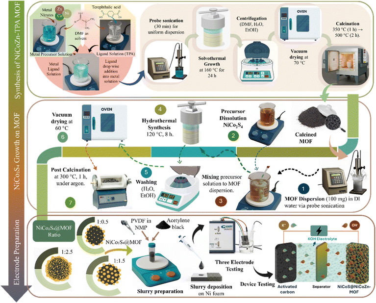 |
| | Fig. 1 Schematic illustration of the synthesis of NiCoZn-MOF, its calcination, NiCo2S4, and the in situ growth of NiCo2S4@NiCoZn-TPA MOF composites. | |
2.3 Calcination of synthesized MOFs
The dried MOF particles were calcined in a ceramic crucible with a loosely covered lid for controlled air access as shown in Fig. 1. The temperature was increased to 350 °C with a heating rate of 2 °C min−1 for 1 hour to break terephthalic acid linkers into a carbonaceous matrix while minimizing structural collapse. The temperature was increased to 500 °C with same heating rate and maintained for 2 h for the oxidation of metal species. Decomposition of the organic framework produced a porous structure, with residual carbon from linker degradation, contributing to enhanced electrical conductivity. The calcination produced a sample A2 consists primarily of NiO, CoO, and ZnO embedded within a residual carbon matrix derived from the decomposed organic linker.
2.4 Synthesis of pristine NiCo2S4
Pristine NiCo2S4, referred to as A3, was synthesized through hydrothermal approach. For this, 1 mmol of Ni(NO3)2·6H2O and 2 mmol of Co(NO3)2·6H2O, were dissolved in de-ionized water under continuous stirring to form a homogeneous solution. Subsequently, 4 mmol of Na2S·9H2O was introduced as the sulfur source, and the mixture was probe-sonicated for 30 min. The resulting solution was hydrothermally treated at 120 °C for 8 h. The synthesized nanoparticles were separated by centrifugation and washed three times each with de-ionized water and ethanol. The purified sample was then dried under vacuum at 60 °C for 12 hours to remove remaining solvents and prevent oxidation of the NiCo2S4 powder. Calcination at 300 °C for 3 hours under argon was employed to enhance crystallinity and phase purity while preventing oxidation and structural degradation.
2.5 Synthesis of NiCo2S4@MOFs composites
NiCo2S4 nanoparticles were grown in situ on calcined NiCoZn MOFs to form NiCo2S4@MOFs composite with varying weight ratios of MOFs to sulfide i.e., 1:0.5, 1:1.5, and 1:2.5, abbreviated as A4, A5, and A6 as depicted in Table 1. For this 100 mg of calcined MOFs was dispersed in de-ionized water via probe sonication for 20 minutes. Separately, appropriate amounts of Ni, Co and S salts were dissolved in the de-ionized water to serve as precursors for NiCo2S4 formation. The precursor solution added dropwise into MOFs dispersion, and the mixture was probe-sonicated for 30 min. The resulting suspension was placed into a 100 mL autoclave and treated hydrothermally at 120 °C for 8 h. After the hydrothermal process, the autoclave was permitted to cool to room temperature. After synthesis, the composites were collected by centrifugation, washed thoroughly with de-ionized water and ethanol to remove impurities, and subsequently dried under vacuum at 60 °C for 12 hours. To enhance crystallinity and strengthen the interfacial contact between the MOFs and sulfide phases, the dried nanocomposites were subjected to a secondary calcination at 300 °C for 3 hours under an argon atmosphere to prevent oxidation as shown in Fig. 1.22
Table 1 Compositional overview of the synthesized samples
| Electrode material |
Ratio of NiCoZn-MOF |
Ratio of calcined MOFs |
Ratio of NiCo2S4 |
| A1 |
1 |
0 |
0 |
| A2 |
0 |
1 |
0 |
| A3 |
0 |
0 |
1 |
| A4 |
0 |
1 |
0.5 |
| A5 |
0 |
1 |
1.5 |
| A6 |
0 |
1 |
2.5 |
2.6 Electrode preparation for electrochemical measurements
For each synthesized material (A1–A6), a separate homogeneous slurry was formulated by combining the active material (A1–A6) with acetylene black and PVDF in an 8:1:1 weight ratio using NMP as solvent as shown in Fig. 1. The resulting mixture was continuously stirred at 200 rpm for 8 hours. The slurry was uniformly dropped-casted onto pre-cleaned nickel foam (1 × 1 cm2, 1.6 mm thickness, Pi-Kem, UK) using micropipette and dried at 70 °C for 8 h. Electrochemical measurements were performed utilizing prepared electrode as working electrode, a platinum wire (counter electrode), and a Hg/HgO as reference electrode using 1 M KOH aqueous solution as the electrolyte. The electrochemical performance of the electrode was evaluated through cyclic voltammetry (CV), galvanostatic charge–discharge (GCD), and electrochemical impedance spectroscopy (EIS). For device assembly, the working electrode was employed as cathode, while activated carbon (AC) prepared through same procedure as discussed above as an anode and Hoffman filter paper as the separator.
2.7 Characterization
The synthesized samples were characterized to evaluate their structural, morphological, and electrochemical properties. X-ray Diffraction (XRD) patterns and Fourier Transform Infrared Spectroscopy (FTIR) spectra were recorded using an AXRD LPD diffractometer (Proto, Ontario, Canada) and a Bruker Alpha Platinum ATR system (New Jersey, USA), respectively. XRD patterns were obtained using Cu-Kα radiation (λ = 1.5418 nm) over a 2θ range of 10–90°. The FTIR measurements were performed within the range of 400–4000 cm−1 with a spectral resolution of 2 cm−1. Surface morphology and elemental composition were analyzed via scanning electron microscopy (SEM) and Energy-Dispersive X-ray (EDX) Spectroscopy (Carl Zeiss EVO 15, Jena, Germany). SEM analysis was conducted at an accelerating voltage of 15 kV, with magnifications varying from 1 kx to 50 kx and a working distance of 8.49 mm. To prevent charging, the synthesized samples were sputtered with a thin gold layer. Electrochemical measurements were conducted using a Gamry Reference 3000 Potentiostat (Warminster, PA, USA).
3 Results and discussion
3.1 Surface morphology and elemental distribution analysis
The surface morphology and elemental area mapping of the synthesized samples pristine NiCoZn-MOFs (A1), calcined MOF's (A2), NiCo2S4 (A3) and composite (A5) were analyzed through SEM and EDX as shown in Fig. 2. The A1 micrographs revealed that the material predominantly adopted plate-like morphology Fig. 2(a1 and b2), where thin layered plates were closely stacked and interconnected. The well-defined edges and smooth surfaces of these plates highlight a uniform coordination between the metal clusters and terephthalate linkers. Such two-dimensional sheet-like structures are advantageous as they provide an increased surface-to-volume ratio and excessive exposed active sites, which facilitates electrolyte penetration and ion transport in subsequent electrochemical processes. Similar plate like morphologies of MOFs are well-established in previous studies: Yang et al. synthesized Zn-MOFs nanosheet arrays with comparable plate-like structures on carbon cloth;23 Ma et al. demonstrated rectangular nanosheet morphologies for trimetallic NiCoM (M = Cu, Fe, Zn) MOFs;24 and Gumilar et al. reported that M-TPA MOFs (M = Cu, Mn, Ni, Zr) adopt diverse hierarchical morphologies, with Ni-TPA in particular exhibiting a multilayered sheet-like architecture consistent with the plate-like structures observed in our pristine MOFs.25 The SEM micrographs of sample A2 exhibit flower-like morphology as shown in Fig. 2(a2 and b2), which stands in clear contrast to the plate-like architecture observed in the pristine framework. Calcination decomposed the terephthalate linkers, driving the transformation of the MOFs into a carbonaceous matrix composed of loosely interconnected nanosheets radiating outward in a hierarchical flower-like assembly, while simultaneously generating mesoporous channels within the structure.26 Such hierarchical, porous architectures are particularly advantageous, as they not only provide a higher density of electroactive sites but also function as a robust and structurally stable template for the in situ growth of secondary phases, thereby ensuring strong interfacial integration and enhanced electrochemical performance.
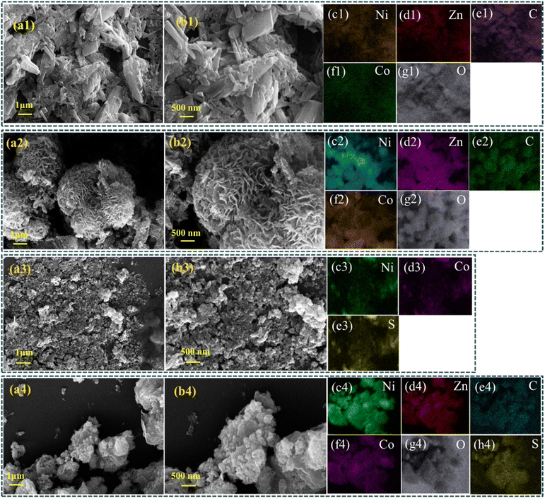 |
| | Fig. 2 SEM images at various magnifications, with the (b) series showing higher magnification, along with EDX elemental area mapping for samples A1 (a1–g1), A2 (a2–g2), A3 (a3–e3) and A5 (a4–h4). | |
Sample A3 exhibits spherical morphology as shown in Fig. 2(a3 and b3). The irregular particle morphology indicates the rapid nucleation and growth dynamics inherent to hydrothermal synthesis. The aggregation of nanoparticles is due to high surface energy, which promotes particle coalescence in the absence of a templating scaffold.27 For the A5 composite, SEM images shown in Fig. 2(a4 and b4) shows that the flower-like structure of the calcined MOFs scaffold is uniformly decorated with NiCo2S4 nanoparticles because of heterogeneous nucleation. This interfacial contact between the conductive sulfide particles and the porous MOFs framework provides a synergistic architecture, where the calcined MOFs scaffold act as a structural backbone while the attached NiCo2S4 nanoparticles serve as highly active electrochemical sites. Such a hierarchical arrangement has improved both electron transport and electrolyte ion accessibility, thereby enhancing the electrochemical performance of the nanocomposite, as will be discussed later in Section 3.3. Similar growth behavior has been reported for NiCo2S4 on rGO nanosheets, where the sheet-like architecture guided nanoparticle nucleation and dispersion.28 Hence, the plate-like MOFs in our study performs an analogous templating role in achieving well-dispersed NiCo2S4 nanoparticles.
The morphological evolution observed in as-prepared nanocomposites, i.e., A5, is also consistent with prior studies on MOFs-derived sulfides. For instance, Wang et al. demonstrated that a Zn-MOF precursor transformed into NiCoZn–S nanosheets decorated with NiCo2S4 nanowires, where the MOFs scaffold directed heterogeneous nucleation and subsequent sulfide growth, yielding a nanoplate like matrix decorated with NiCo2S4 particles.23 Similarly, scaffold-assisted growth on carbon substrates, nickel foams, or nanosheet frameworks has been shown to promote the controlled nucleation of NiCo2S4, leading to nanocomposite architectures with enhanced structural integrity and electrochemical activity.29
The EDX mapping of A1 (Fig. 2(c1–g1)) shows a homogeneous dispersion of Ni, Co, Zn, C, and O, confirming the successful incorporation of multiple metal centers into the organic framework. In A2 as shown in Fig. 2(c2–g2), slightly higher C and O content is observed, also shown in Fig. S1(b) EDX energy plot, attributed to the formation of the carbonaceous framework and metal oxides. Fig. 2(c3–e3) represents the EDX mapping of sample A3 with uniform distribution of Ni, Co, and S, validating the presence of ternary sulfide phase. For the composite A5 shown in Fig. 2(c4–h4), the coexistence of Ni, Co, C and O along with uniform distribution of Zn (from the MOF) and S (from NiCo2S4), represents the integration in situ grown sulfide phase on the MOFs-derived carbonaceous/metal oxide matrix. These observations are in agreement with previous studies on NiCo2S4/rGO nanocomposites, where EDX mapping confirmed homogeneous dispersion of Ni, Co, and S within the nanoparticles.30
3.2 Structural and phase characteristics
XRD analysis of sample A1 as shown in Fig. 3(a) showed sharp and well-defined diffraction peaks, confirming the formation of a highly crystalline framework. These reflections originate from the periodic coordination of terephthalate linkers with Ni, Co and Zn metal centers, indicative of a well-ordered MOFs structure. The reflections at 14.2°, 15.7°, and 17.7° indexed to planes (001), (201), and (400), respectively are consistent with previously reported metal-TPA structures.31 Literature reports have shown that monometallic Ni, Co and Zn and bimetallic NiCo-TPA MOFs are isostructural and exhibit nearly identical diffraction patterns. In agreement with these findings, the characteristic reflections observed in our sample A1 at 15.7° and 17.8° closely match those reported for CCDC 985792 (Ni-MOF) and CCDC 153067 (Co-MOF)32 confirming the structural analogy of the trimetallic NiCoZn-TPA MOF with its bimetallic and monometallic counterparts. Furthermore, Zn-TPA MOF displays characteristic peaks at 13.7° and 17.8° arising from the (400) and (420) planes, respectively.33 Reflections at 14.4°, 15.0°, 15.4°, 17.8°, 24.0°, 25.1°, 26.3°, 28.4°, 30.1°, 33.8°, and 56.4° are also consistent with literature reports on CuZn-MOFs, confirming the structural analogy of our material with previously reported terephthalate-based frameworks.34 This structural similarity verifies the successful formation of trimetallic MOFs.
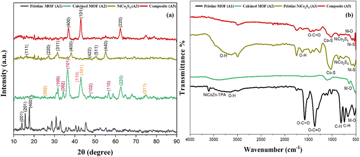 |
| | Fig. 3 (a) XRD and (b) FTIR spectra of the pristine MOF (A1), calcined MOF (A2), pristine NiCo2S4 (A3), and NiCo2S4@MOF composite (A5). | |
For sample A2, upon calcination, the characteristic MOF peaks diminished in intensity and the sharp low-angle peaks (10–20°) disappeared, confirming the degradation of the terephthalate linkers as shown in Fig. 3(a). New diffraction signals emerged from transition-metal oxides generated during calcination, while the peak at 43° corresponding to (101) evidenced carbon residues originating from linker decomposition.35–37 Sample A2 showed reflections at 36.5° and 43° corresponding to (101) and (110) planes were indexed to CoO (JCPDS 65-5474),35 those at 62.8° (220) and 75.4° (311) corresponded to NiO (JCPDS 47-1049),38 while peaks at 31.7° (100), 34.6° (002), 36.5° (101), 47.5° (102), and 56.5° (110) matched ZnO (JCPDS 36-1451).39 These transformations suggest that thermal decomposition of the organic linkers produced carbon-rich matrix embedded with mixed metal oxide phases. For specimen A3, diffraction peaks located 16.3°, 27.2°, 31.6°, 38.3°, 47.4°, 50.5°, and 55.3° were indexed to the (111), (220), (311), (400), (422), (511), and (440) planes of NiCo2S4, and correspond to JCPDS card no. 20–0782.40 The composite (A5) shows reflections corresponding to both crystalline NiCo2S4 and MOF-derived oxide/carbon phases, confirming the co-existence of sulfide nanoparticles along with calcined MOFs. A distinct reflection at 36.8° is indexed to the (400) plane of NiCo2S4, while the broad feature at 43° is attributed to the carbon content. Additionally, the reflection at 62° indexed to the (220) plane of NiO indicates the presence of an oxide phase from calcined MOFs. Other low-intensity features are suppressed into the background due to the nanoscale dimensions of the composite. These results further demonstrate the integration of NiCo2S4 with the MOFs-derived oxide/carbon phases, suggesting strong interfacial contact between the sulfide nanoparticles and the conductive matrix.
While XRD established the crystalline phases and phase evolution, FTIR analysis was performed to elucidate changes in the organic linker vibrations and metal–ligand interactions resulting from calcination and subsequent sulfide growth. The FTIR spectrum of the sample A1 exhibited several characteristic peaks corresponding to its organic linker and metal ligand coordination as shown in Fig. 3(b). A broad band at 3435 cm−1 corresponds to –OH stretching vibrations.41 The sharp band at 3606 cm−1 is indicative of coordination between Ni, Co, and Zn metal centers and the terephthalate linkers. Bands at 1575 cm−1 and 1365 cm−1 arise from the asymmetric and symmetric stretching of carboxylate groups, respectively, while the signal at 813 cm−1 is attributed to aromatic C–H bending. Bands observed between at 500 to 700 cm−1 is indicative of M–O stretching (Ni–O/Co–O/Zn–O), further confirming the successful formation of the MOFs.24 Sample A2 indicates the absence of carboxylate groups and C–H peaks, due to linker degradation. The presence of M–O stretching peak at low wavelength region corresponds to the formation of metal oxides after calcination.
The sample A3 displayed characteristic metal-sulfur bonding with signal observed at 670 cm−1 due to bending vibration of NiCo2S4.42 Peaks at 525 and 1020 cm−1 were attributed to Ni–S and Co–S stretching, respectively, while weak signals at 1631 and 3425 cm−1 indicated OH vibrations from adsorbed water molecules.43 For composite A5, the FTIR spectrum exhibited the characteristic features of both the calcined MOFs and NiCo2S4, validating their successful integration. Vibrations corresponding to the asymmetric and symmetric modes of carboxylate groups from the TPA linker were still observed at 1575 cm−1 and 1365 cm−1, along with the benzene C–H bending vibration at 813 cm−1, however, slight shifts in peak positions and noticeable changes in intensities were observed in the composite, particularly in the metal–ligand coordination region and the M-S stretching region. The attenuation and minor wavenumber shift of the MOF-related bands can be ascribed to the combined effects of air calcination, which partially decomposes the organic linker, and the coordination interactions resulting from the anchoring of NiCo2S4 nanoparticles on the MOF surface. Meanwhile, sulfide-specific vibrations were clearly detected at 525 cm−1 (Ni–S), 670 cm−1 (NiCo2S4), and 1020–1120 cm−1 (Co–S stretching). Peaks near 528 cm−1 appears due to combined contributions from metal oxide and sulfide bond vibrations.
3.3 Electrochemical characterization
3.3.1 Three electrode testing. CV analyses were performed in a three-electrode configuration over a potential window of 0–0.7 V across scan rates varying from 2–100 mV s−1 (Fig. 4) to evaluate the charge storage performance and electrochemical characteristics of synthesized samples. CV of the sample A1 (Fig. 4a) shows pronounced, well-defined redox peaks that grow systematically with scan rate, confirming a dominant faradaic pseudocapacitive process associated with Ni2+/Ni3+ and Co2+/Co3+ transitions coupled with OH− insertion/extraction. The peak currents increase with scan rate, and the CV curves maintain their shape over the entire range, indicating fast charge-transfer kinetics and efficient ion diffusion across MOF's porous framework. Sample A2 as shown in Fig. 4(b), the current response reduced due to the formation of metal oxides after calcination which reduces the accessible electroactive sites for redox reactions. Although calcination generates a carbonaceous matrix with enhanced conductivity and a porous network. The simultaneous formation of less electroactive metal oxides suppresses redox activity, thereby reducing the overall current response.
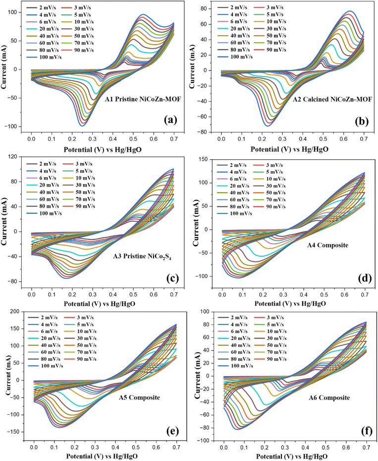 |
| | Fig. 4 CV curves for samples A1 (a), A2 (b), A3 (c), A4 (d), A5 (e) and A6 (f) over potential window of 0–0.7 V at various scan rates from 2–100 mV s−1. | |
CV curves of sample A3 (Fig. 4(c)) showed higher current response than both the pristine and calcined MOF. This is due to superior conductivity and abundant redox-active sites, which promotes rapid electron transfer and multiple faradaic transitions. However, at higher scan rates, the CV curves exhibited slight peak broadening due to reduced ion diffusion within the dense sulfide structure. Thus, while NiCo2S4 offers superior conductivity and rich redox chemistry, the absence of a porous support limits electrolyte penetration and restricts the full utilization of the active sites at higher scan rates.44
The CV curve for composites with varying mass ratios revealed a clear dependence of redox activity on the sulfide content. At the 1:0.5 ratio composite A4 as shown in Fig. 4(d), the CV curves exhibited distinct redox peaks with current response higher than A1–A3, evidencing the impact of NiCo2S4 to the pseudocapacitive process. However, the relatively low sulfide loading provides less electroactive sites, leading to less efficient utilization of MOF-derived conductive framework. When the ratio was increased to 1:1.5 (A5) as given in Fig. 4(e), the redox peaks became more pronounced with significantly higher current densities, indicating a well-balanced integration of NiCo2S4 nanoparticles within the porous MOF matrix.45 This composition maximized the synergy between the conductive sulfide phase and the porous MOF, promoting rapid electron transfer and efficient electrolyte ion diffusion. In contrast, at the 1:2.5 ratio A6 shown in Fig. 4(f), the CV profiles showed reduced current response. The excessive loading of NiCo2S4 caused agglomeration and reduced mesoporosity within the calcined-MOF scaffold, restricting electrolyte penetration and reducing the availability of redox-active sites. Moreover, structural congestion at high sulfide content impedes ion diffusion pathways and reduces the intrinsic advantage of the MOF's porous network.46 Thus, the electrochemical results clearly establish that the A5 composite offers the most effective balance between structural accessibility and electrochemical activity.
For quantitative assessment of charge storage capability of the synthesized samples A1–A6, GCD measurements were performed. All samples displayed non-linear discharge shape as shown in Fig. 5. This behavior is attributed to pseudocapacitive faradaic redox reactions, coinciding with the by CV results of distinct redox peaks. At lower current densities all electrodes discharge with longer durations due to efficient utilization of electrode structure. With increase in current density, the discharge time decreased due to limited penetration of electrolyte within the electrode structure, limiting charge storage to electrode's outer surface. The sample A1 displayed moderate discharge times at 0.55 V with clear pseudocapacitive behavior as shown in Fig. 5(a). The moderate voltage drop due to the internal resistance (IR) is observable, but the overall GCD results remains reversible throughout all current densities. For sample A2, the shorter discharge time compared to sample A1 as depicted in Fig. 5(b), due to the formation of less electroactive metal oxides. The reduced IR drop for sample A1 arises due to enhanced electronic conductivity of the carbonaceous network despite its lower overall capacitance. This trade-off between conductivity enhancement and loss of electrochemical activity accounts for its moderate charge storage performance. Fig. 5(c) shows that the sample A3 exhibited significantly longer discharge times than A1 and A2, confirming its superior charge storage owing to high conductivity and multiple redox couples (Ni2+/Ni3+, Co2+/Co3+). Slightly larger IR drops at higher currents indicate diffusion-related limitations. GCD measurements of the MOF@NiCo2S4 composites show a clear composition–performance relationship. Composite A5 shown in Fig. 5(e) exhibits enhanced discharge times compared to A4 and A6, balancing abundant sulfide redox sites and the porous MOFs structure. Lower sulfide loadings limited capacity, while higher loadings caused agglomeration and reduced mesoporosity increasing resistance and reducing accessibility can be verified from the SEM results shown in Fig. S2.
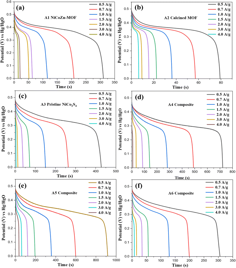 |
| | Fig. 5 GCD measurements of (a) A1, (b) A2, (c) A3, and (d–f) NiCo2S4@MOF composites A4–A6 measured within 0–0.5 V at current densities of 0.5–4 A g−1. | |
3.3.2 Comparative assessment of electrode materials. Comparative CV curves at 10 mV s−1 scan rate and GCD measurements at 0.5 A g−1 were employed, which provides an appropriate balance between electrolyte ion diffusion and surface-controlled processes. As shown in Fig. 6(a), electrodes A1 and A2 exhibit pronounced redox peaks attributed to the redox reactions of transition metal ions, whereas A3–A6 display quasi-rectangular profiles with clear redox features, indicative of hybrid charge storage behavior arising from both EDLC and pseudocapacitance. Among these, A5 presents the largest enclosed area, signifying superior charge storage capacity. In contrast, the calcined MOF (A2) and the high-loading composite (A6) deliver the weakest responses, with the lowest current responses and smallest integrated areas, reflecting limited electrochemical activity. Bothe the CV GCD results complement each other as displayed in Fig. 6(b), which revealed nearly symmetric charge–discharge curves for all electrodes, confirming good electrochemical reversibility. Among all samples, A5 exhibits the longest discharge durations, due to optimized ratio of conductive framework and sulfide content. Samples A2 and A6 display much shorter discharge times, underscoring their inferior charge storage performance. The Qs of the electrodes were calculated using the following relation:41| |
 | (i) |
where Δt (s) is the discharge time, I (A) is the applied current, and m (g) is active material's mass. The pristine MOF (sample A1) exhibited the Qs of 155.5 C g−1. NiCo2S4 incorporation enhanced the charge storage performance of optimized electrode to 458.5 C g−1.
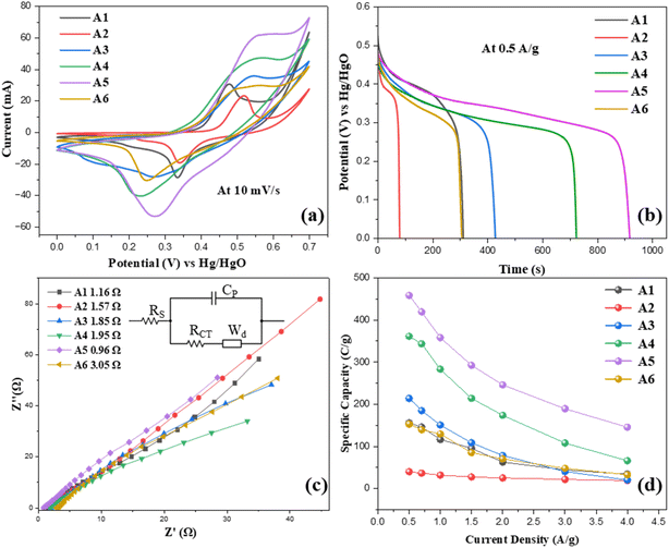 |
| | Fig. 6 Electrochemical comparative (a) CV curves, (b) GCD profiles, (c) Nyquist plots and (d) specific capacity variation along with current density of prepared A1–A6 electrodes. | |
EIS analysis were conducted over the frequency range of 1–100000 Hz to gain insights into the electrode–electrolyte interfacial resistance and charge transfer characteristics. The Nyquist plots of samples A1–A6 are presented in Fig. 6(c). The equivalent series resistance (ESR), calculated through circuit fitting model, gives the combined contributions of the intrinsic resistance of the active material, the electrode–electrolyte interfacial resistance, and the ionic resistance of the electrolyte. The calculated ESR values for A1, A2, A3, A4, A5, and A6 were 1.16, 1.57, 1.857, 1.95, 0.96, and 3.05 Ω, respectively, with A5 exhibiting the lowest resistance values. Among all the electrodes, A5 shows the lowest ESR, highlighting its superior electrochemical performance. Electrode A6 shows the highest resistance, due to slow charge transfer results from reduction in mesoporosity due to high sulfide content. The absence of semicircle features in the high frequency region highlights negligible charge transfer resistance (Rct) in all electrodes.
The Qs of the electrodes calculated using eqn (i), shown in Fig. 6(d). The graph displayed the inverse relationship between capacity and current density due to the restricted ion diffusion and inadequate penetration of electrolyte ions into the internal active sites under rapid charge–discharge conditions. At 0.5 A g−1, the Qs was 155.6, 39.9, 213.9, 361.4, 458.5, and 152.9 C g−1 for A1, A2, A3, A4, A5, and A6, respectively. The A2 electrode's lower Qs represents the formation of less electroactive metal oxides during calcination. A3 delivered higher values than the pristine and calcined MOFs (A1 and A2), reflecting its enhanced conductivity and abundance of redox-active sites. The composites A4 and A5 outperformed pristine sulfide sample A3, representing that combining NiCo2S4 with the porous MOF significantly improved ion diffusion, charge transfer, and utilization of electroactive sites, whereas A6, with reduced mesoporosity, showed reduced electrochemical performance. Among all samples, A5 achieved the highest capacity response and, attributed to the optimal synergy between NiCo2S4 and the MOF derived framework.
3.3.3 Electrochemical analysis of NiCoZn oxide@carbon nanocage/NiCo2S4‖AC device. To assess the electrochemical properties of the NiCoZn oxide@carbon nanocage/NiCo2S4 composite for practical implementations, a hybrid asymmetric supercapacitor was assembled. For this configuration, A5 functioned as the cathode and AC as the anode, with α-cellulose as separator impregnated in 1 M KOH solution. Electrochemical analysis including CV, EIS, GCD, capacitive-diffusive analysis, and cycling stability tests, were conducted to assess the device performance. Fig. 7(a) compares the CV responses of the individual electrodes. For the AC electrode, the CV response at 0 to −1 V potential displayed a nearly rectangular profile with no evident redox peaks, demonstrating an EDLC dominated charge storage pathway. In contrast, A2 electrode's CV curve results at 0 to 0.7 V potential range exhibited distinct anodic and cathodic peaks, characteristic of faradaic redox reactions associated with transition-metal sulfides, confirming its pseudocapacitive contribution. For the optimization of highest operating potential window of the hybrid device, CV tests were performed under varying voltages (0–1.7 V) as depicted in Fig. 7(b). The current response gradually increased as the potential window expanded, and the CV curves remained well defined and stable up to 1.7 V, showing no significant distortion. This confirms the electrochemical robustness of the device and demonstrates that the assembled system can safely operate at an extended potential.
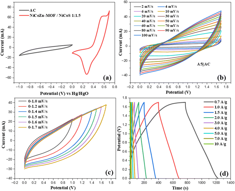 |
| | Fig. 7 A5‖AC device electrochemical (a) CV analysis for composite A5 and AC in a three-electrode setup at 10 mV s−1; (b) CVs under varying potential windows (0–1.0 to 1.7 V); (c) CVs at 2–100 mV s−1; (d) GCD analysis at 0–1.7 potential. | |
The CV response of hybrid device was evaluated at scan rates of 2–100 mV s−1 within the optimized voltage window of 0–1.7 V to evaluate its charge storage mechanism as presented in Fig. 7(c). The CV profiles displayed quasi-rectangular, reflecting a combined charge storage mechanism. The AC electrode contributes EDLC through electrostatic ion adsorption/desorption, while the A5 electrode provides additional capacitance contributed by redox-mediated pseudocapacitive processes transition-metal sulfides. At lower scan rates, the curves response suggests more effective utilization of electroactive sites due to sufficient ion diffusion. With increasing scan rates, the CV curves gradually expanded but preserved their overall quasi-rectangular shape without noticeable distortion, indicating highly reversible hybrid charge storage from both electrodes. GCD measurements as illustrated in Fig. 7(d) of the A5‖AC hybrid device were carried out at 0–1.7 V potential range with (0.7–10 A g−1) current densities. The GCD profiles confirmed the coexistence of EDLC behavior from the AC electrode and faradaic contributions from the A5 electrode.
3.3.4 Electrochemical impedance, Ragone plot and stability analysis. The EIS of the A5‖AC device, measured prior to and following the cycling stability evaluation, as shown in Fig. 8(a). Both spectra exhibit a small intercept on the real axis, indicating a low equivalent series resistance (ESR), which is crucial to attain rapid charge transport and efficient ion diffusion. The ESR increased slightly from 0.475 Ω before cycling to 0.630 Ω after cycling, which can be attributed to minor changes at interface between the electrode and the electrolyte and partial loss of active sites. Nevertheless, the low ESR values confirm the excellent conductivity and robust interfacial contact of the electrodes. The high-frequency semicircle, associated with charge-transfer resistance, remains nearly unchanged before and after stability, whereas the low-frequency tail becomes marginally more tilted compared to the initial state, suggesting a minor increase in diffusion resistance and reduction in accessible active sites. Stability performance of the device was evaluated by performing 5000 GCD cycles at 7 A g−1 as presented in Fig. 8(b). The device maintained 80.14% of its initial capacity along with nearly constant coulombic efficiency of 98.53%. The slight capacity decay is due to framework degradation after repeated redox-induced strain, surface passivation, and restricted ion transport within deeper pores over prolonged cycling.47 The coulombic efficiency demonstrates the high reversibility and excellent electrochemical performance of the hybrid device.
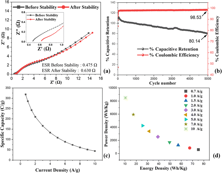 |
| | Fig. 8 Electrochemical evaluation of (a) Nyquist plot before and after the stability, (b) cycling stability showing capacitive retention and coulombic efficiency over 5000 cycles, (c) Qs across various current densities and (d) Ragone plot illustrating Ed and Pd. | |
The device's rate performance over range of current densities (0.7–10 A g−1) is illustrated in Fig. 8(c). At lower current density, the device achieved Qs of 320 C g−1, due to efficient utilization of active sites under slow charge–discharge rates. With increase in current density, the Qs declines reaching 45 C g−1 at 10 A g−1. This trend is typical for pseudocapacitive and hybrid devices, as elevated current densities restricts the diffusion of electrolyte ions within the electrode structure. Despite this decrease, the device preserved a significant fraction of its capacity even at high current rates, demonstrating superior rate capability and fast charge transport kinetics. The Ragone plot in Fig. 8(d) illustrates the device's energy and power characteristics, with Ed and Pd calculated using the following relationships:48
| |
 | (ii) |
| |
 | (iii) |
The A5‖AC device achieved highest Ed of 75.23 W h kg−1 at a Pd of 595 W kg−1, while retaining Ed 14.5 W h kg−1 even at a higher Pd of 6800 W kg−1. This optimum between Ed and Pd arises from the synergistic combination of faradaic redox activity at the A5 electrode and the rapid surface-driven capacitance of the AC electrode. These results clearly demonstrate that the A5‖AC hybrid supercapacitor possesses low internal resistance, outstanding cycling stability, strong rate capability, and excellent energy–power balance.
3.3.5 Comparison with literature. Compared with previously reported MOF-derived and NiCo2S4-based composites as shown in Table 2, the NiCo2S4@MOF developed in this study exhibits distinct improvements in structural design and electrochemical performance. Earlier studies have reported that NiCo2S4 nanostructures and MOF-derivates often exhibit lower Ed and Pd, insufficient electrical conductivity, and gradual structural deterioration during prolonged cycling. In contrast, the calcined trimetallic MOF precursor employed here provided a robust carbonaceous-metal oxide scaffold after calcination, which facilitated homogeneous nucleation of NiCo2S4 nanoparticles and stronger interfacial coupling. This well-engineered structural integration led to improved charge transport, higher utilization of electroactive sites, and enhanced cycling durability.
Table 2 Comparison of MOF-based hybrid supercapacitors from literature and the present work
| Cathode‖anode |
Synthesis route |
Morphology |
Electrolyte/Potential window |
Ed (W h kg−1) and Pd (W kg−1) |
Capacitance retention |
Ref. |
| CF@NiCoZn–S/NiCo2S4‖CNS-CNTs |
MOF-derived + hydrothermal sulfurization |
3D hierarchical nanoarrays (nanosheets + nanowires on carbon fibers) |
6 M KOH/0–1.7 V |
48.7/800 |
70.1% after 10000 cycles |
23 |
| NiCo-DH/3D-MWCNT/NiF‖AC |
Hydrothermal growth of 3D-MWCNT + electrodeposition |
3D porous CNT network with NiCo-DH nanosheets |
2 M KOH/0–1.5 V |
30.99/427.46 |
84.7% after 2000 cycles |
49 |
| NiCo-MOF‖AC |
Solvothermal + cation-exchange |
Hydrangea-like, ultrathin hierarchical MOFs |
2 M KOH/1.6 V |
45.3/847.8 |
82.4% after 7000 cycles |
50 |
| NiCoZnS‖AC |
Hydrothermal + post-sulfurization |
Urchin-like |
6 M KOH/1.5 V |
57.8/750 |
79.2% after 10000 cycles |
51 |
| NCO@C/N-LDH‖AC |
Hydrothermal method |
Hierarchical core–shell: NiC2O4 backbone coated with C/N-doped NiCoZn-LDH nanosheets |
3 M KOH/0–1.6 V |
56.9/800 |
|
52 |
| ZnNiCo MOF‖AC |
Zn incorporation into hydrothermally synthesized NiCo-MOF |
Nanosheet |
2 M KOH/0–1.5 V |
58/775 |
60% after 3000 cycles |
53 |
| NiCo2S4@MOF composite |
Hydrothermal synthesis of the MOF, followed by calcination and subsequent in situ growth of sulfide particles |
Porous flower-like MOF decorated with NiCo2S4 nanoparticles |
1 M KOH/0–1.7 V |
76/700 |
80% after 5000 cycles |
This work |
3.3.6 Electrochemical charge storage pathways in NiCo2S4@MOF composite. Understanding the mechanisms of charge storage is essential for optimizing the electrochemical behavior of MOF-derived composites. In this study, the progression from NiCoZn-TPA MOF to calcined MOF and finally to NiCo2S4@calcined MOF reveals a charge storage from surface redox activity to a synergistic hybrid mechanism as displayed in Fig. 9. The pristine NiCoZn-TPA MOF features abundant redox-active metal centers (Ni, Co, and Zn) coordinated with terephthalate linkers. Under alkaline electrolyte conditions, the Ni and Co centers actively participate in reversible faradaic transitions, whereas Zn primarily functions as a structural stabilizer, contributing to the overall framework integrity during cycling. The representative electrochemical reactions can be expressed as:54| | |
Ni2+ + OH− ↔ Ni(OH)2
| (iv) |
| | |
Ni(OH)2 + OH− ↔ NiOOH + H2O + e−
| (v) |
| | |
Co2+ + 2OH− ↔ Co(OH)2
| (vi) |
| | |
Co(OH)2 + OH− ↔ CoOOH + H2O + e−
| (vii) |
 |
| | Fig. 9 Schematic depiction of charge storage processes in the asymmetric supercapacitor device. | |
MOFs exhibit charge storage behavior that is predominantly controlled by pseudocapacitive mechanisms associated with the reversible redox activity of Ni and Co centers, while a minor contribution arises from EDLC facilitated by its porous framework. Upon calcination, the organic terephthalate linkers decompose to yield a conductive carbonaceous matrix, while the incorporated metal centers are converted into their respective oxides (NiO, CoO, and ZnO). Although A2 exhibits enhanced conductivity due to the carbonaceous framework, its redox activity remains limited by the intrinsically low electrochemical reactivity of metal oxides. In this transformed state, the carbon framework contributes to EDLC through non-faradaic adsorption of electrolyte ions at the electrode–electrolyte interface, whereas the transition metal oxides introduce substantial pseudocapacitance via reversible redox reactions. However, the redox activity is limited by the intrinsically low electrochemical reactivity of metal oxides given by the following equations:55
| | |
NiO + OH− ↔ NiOOH + e−
| (viii) |
| | |
CoO + OH− ↔ CoOOH + e−
| (ix) |
| | |
NiOOH + OH− ↔ NiO2 + H2O + e−
| (x) |
| | |
CoOOH + OH− ↔ CoO2 + H2O + e−
| (xi) |
Redox activity is enhanced by growing NiCo2S4 nanoparticles on the calcined MOF scaffold, as evident from the electrochemical response discussed in earlier sections. This offers multiple oxidation states of Ni (Ni2+/Ni3+) and Co (Co2+/Co3+), which undergo fast and reversible faradaic reactions in alkaline electrolyte. The overall processes can be simplified as:56,57
| | |
NiS + OH− ↔ NiSOH + e−
| (xii) |
| | |
CoS + OH− ↔ CoSOH + e−
| (xiii) |
| | |
CoSOH + OH− ↔ CoSO + H2O + e−
| (xiv) |
| | |
NiSOH + OH− ↔ NiSO + H2O + e−
| (xv) |
Or more generally represented as:
| | |
NiCo2S4+ 3OH− ↔ NiOOH + 2CoOOH + 4S2− + 3e−
| (xvi) |
In this composite, the porous conductive carbon/oxide matrix derived from the MOF not only contributes to EDLC behavior but also provides mechanical stability, efficient electron pathways, and efficient anchoring site for NiCo2S4 nanoparticles. Meanwhile, NiCo2S4 nanoparticles serve as the dominant redox-active component, supplying high pseudocapacitance through multi-electron processes. Thus, the NiCo2S4@calcined MOF electrode exhibits a hybrid charge storage mechanism, integrating EDLC from carbon, pseudocapacitance from residual oxides, and rich faradaic activity from NiCo2S4, leading to superior capacitance, rate performance, and cycling durability.
3.3.7 Capacitive and diffusive nature analysis. The electrochemical charge storage of the NiCo2S4@NiCoZn-MOF‖AC hybrid electrode was further examined by distinguishing the contributions from diffusion and capacitive-controlled processes. To achieve this, Dunn's method was employed, which enables separation of the current response from cyclic voltammogram into surface-limited and diffusion-dependent components. The overall current response i(V) of the actual device originates from the combined contributions of faradaic reactions governed by electrolyte ion diffusion i(F) and surface-limited non-faradaic (capacitive) processes i(nF).| | |
i(V) = i(F) + i(nF)
| (xvii) |
| | |
i(V) = i(F) + i(nF) = Kav + Kbv1/2
| (xviii) |
where, Kav represents the surface-controlled component, while Kbv1/2 corresponds to the diffusion-controlled process.58From this analysis, it was determined that at 10 mV s−1 the electrode delivers 26.2% of its charge via capacitive storage, while 73.8% is associated with diffusion-limited faradaic reactions. The capacitive contribution is mainly attributed to the EDLC and fast redox reactions of the carbonaceous framework, while the pseudocapacitance arises primarily from faradaic redox reactions of NiCo2S4 nanoparticles and embedded metal oxide species. The deconvoluted CV curve (Fig. 10(a)) highlights the capacitive region as a gradient green nested within the total response. As reported in prior studies, carbon frameworks (e.g., AC, CNTs, MOF-derived carbons) contribute primarily through electrostatic capacitance, in contrast to transition metal sulfides, whose charge storage is governed by pseudocapacitive, diffusion-dependent redox processes.59
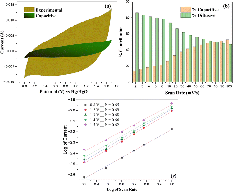 |
| | Fig. 10 Analysis of charge storage response in hybrid device (a) CV response at 10 mV s−1, with the green-shaded area represents capacitive contribution (b) variation of EDLC and faradaic contributions across different scan rates (c) log(i)–log(v) plots showing the corresponding b-values. | |
In addition, the variation in contributions across different scan rates is summarized in Fig. 10(b), which shows a clear tendency for capacitive behavior to increase with increasing scan rates. This variation reflects the charge storage response from both contributions, at low scan rates, ions have adequate duration to access the bulk structure, resulting in diffusion-dominated mechanisms, whereas at higher scan rates, limited ion diffusion confines the process to the electrode surface, dominating the capacitive behavior. These optimized mechanisms confirms the hybrid storage character of the A5‖AC device.
To further substantiate the proposed mechanism, the correlation between log peak current (i) and scan rate (v) was examined in ref. 60:
The slope of graph log of current and scan rate demonstrates the dominant charge storage mechanism: b-value of 0.5 corresponds to a pseudocapacitive response, while a value near 1.0 indicates capacitive behavior. The extracted b-values for our device lies within the range of 0.62–0.69 shown in Fig. 10(c), confirming that the charge storage arises from dominant pseudocapacitive response. Since these values are closer to 0.5, the results corroborate the dominance of diffusion-controlled faradaic reactions, with capacitive contributions also playing a vital role. This observable mechanism demonstrates the hybrid charge storage behavior of the device, where the balance between capacitive and diffusion-controlled processes underpins its superior charge storage performance.
4 Conclusions
A MOFs derived metal oxide/carbon@NiCo2S4 nanocomposite was synthesized by employing a calcined trimetallic NiCoZn-MOF as a porous metal oxide-carbon template for the in situ growth of NiCo2S4 nanoparticles. SEM analysis showed a morphological transformation from plate-like MOF sheets to flower-like porous carbon/metal oxide template, uniformly decorated with spherical NiCo2S4 nanoparticles. The XRD and FTIR analyses confirmed the successful preparation of the pristine MOF, its calcined derivative, and the resulting nanocomposites. The optimized A5 (1 wt% calcined-MOFs/1.5 wt% NiCo2S4) electrode exhibited a high Qs of 458.5 C g−1, while the corresponding asymmetric supercapacitor delivered an Ed of 76 W h kg−1 at a Pd of 700 W kg−1, maintaining 98% coulombic efficiency and 80.01% capacitance retention after 5000 cycles. Furthermore, Dunn's model and power-law fitting analysis revealed its hybrid supercapacitor behavior, with a dominant diffusive contribution of 76% at 10 mV s−1. These findings demonstrate that MOF-derived NiCo2S4 composites synergistically integrate conductivity, structural robustness, and abundant redox-active sites, providing a viable strategy for next-generation high-performance supercapacitor electrodes.
Author contributions
Areeba Sajid: conceptualization, methodology, formal analysis, software, writing – original draft, data curation. Mohsin Ali Marwat: conceptualization, investigation, writing – review & editing, supervision, funding acquisition, project administration. Syed Shaheen Shah: software, writing – original draft, writing – review & editing, visualization. Hamza Mohsin: software, validation, visualization, writing – review & editing. Muhammad Arqam Karim: formal analysis, writing – original draft. Muhammad Tariq: visualization, writing – review & editing, Zuhair Ehsan: formal analysis, writing – original draft, Anusha Arif: visualization, writing – review & editing.
Conflicts of interest
The authors declare that they have no known competing financial interests or personal relationships that could have appeared to influence the work reported in this paper.
Data availability
The data that supports the findings of this study are available upon reasonable request with the first author.
Supplementary information (SI) is available. See DOI: https://doi.org/10.1039/d5ra09542e.
Acknowledgements
M.A. Marwat acknowledges the valuable academic and research support from Pakistan Science Foundation (PSF) Project No. PSF-NSFC/202307/19 and Ghulam Ishaq Khan (GIK) Institute of Engineering Sciences and Technology.
References
- G. Chaturvedi, et al., A systematic approach for selecting suitable morphologies for supercapacitor applications through morphological stability map – A case of Ni-MOF, Ceram. Int., 2023, 49(6), 9382–9394 CrossRef CAS.
- B. Chameh, et al., MOF derived CeO2/CoFe2O4 wrapped by pure and oxidized g-C3N4 sheet as efficient supercapacitor electrode and oxygen reduction reaction electrocatalyst materials, Ceram. Int., 2022, 48(15), 22254–22265 CrossRef.
- S. Ramesh, et al., Fabrication of NiCo2S4 accumulated on metal organic framework nanostructured with multiwalled carbon nanotubes composite material for supercapacitor application, Ceram. Int., 2022, 48(19, Part B), 29102–29110 CrossRef CAS.
- E. I. Duden, et al., Boosting the Ceramics with In Situ MOF-Derived Nanocarbons, ACS Mater. Lett., 2023, 5(6), 1537–1545 CrossRef CAS.
- J. Liu, et al., In Situ Growth of Nanorod-Shaped Ni,Co-MOF on Mo2CTx MXene Surface to Realize Enhanced Energy Storage for Supercapacitors, ACS Appl. Mater. Interfaces, 2024, 16(37), 49380–49391 CrossRef CAS PubMed.
- I. Arshad, et al., Enhanced electrochemical performance of NiCoMn MOFs with Ag-citrate/SWCNT nanocomposites for high-energy supercapacitors, Diamond Relat. Mater., 2025, 155, 112246 CrossRef CAS.
- H. Meng, et al., Conductive Metal–Organic Frameworks: Design, Synthesis, and Applications, Small Methods, 2020, 4(10), 2000396 CrossRef CAS.
- S.-J. Shin, et al., Metal–Organic Framework Supercapacitors: Challenges and Opportunities, Adv. Funct. Mater., 2024, 34(43), 2308497 CrossRef CAS.
- D. Sheberla, et al., Conductive MOF electrodes for stable supercapacitors with high areal capacitance, Nat. Mater., 2017, 16(2), 220–224 CrossRef CAS PubMed.
- A. H. Anwer, et al., Synergistic effect of carbon nanotube and tri-metallic MOF nanoarchitecture for electrochemical high-performance asymmetric supercapacitor applications and their charge storage mechanism, J. Alloys Compd., 2023, 955, 170038 CrossRef CAS.
- M. A. Marwat, et al., Enhancing supercapacitor performance of Ni–Co–Mn metal–organic frameworks by compositing it with polyaniline and reduced graphene oxide, RSC Adv., 2024, 14(3), 2102–2115 RSC.
- W. Wang, et al., MOFs-Based Materials with Confined Space: Opportunities and Challenges for Energy and Catalytic Conversion, Small, 2024, 20(37), 2311449 CrossRef CAS PubMed.
- J.-K. Sun and Q. Xu, Functional materials derived from open framework templates/precursors: synthesis and applications, Energy Environ. Sci., 2014, 7(7), 2071–2100 RSC.
- Y. Yang, M. Li and X. Hu, Self-Assembled Carbon Metal–Organic Framework Oxides Derived from Two Calcination Temperatures as Anode Material for Lithium-Ion Batteries, Molecules, 2024, 29, 3566, DOI:10.3390/molecules29153566.
- A. Sajid, et al., Silver citrate engineered NiCo2S4/MOF-derived oxide@carbon frameworks for high-energy hybrid supercapacitors, RSC Adv., 2026, 16(8), 7252–7270 RSC.
- Z. Dong, et al., Photo-assisted charging of heterostructured NiCo2S4@NiCo-LDH composite electrode with remarkable photoelectronic memory effect for high-performance asymmetric supercapacitor, Energy Convers. Manage., 2024, 315, 118769 CrossRef CAS.
- A. Liu, et al., Cobalt sulfide nanosheets decorated on polypyrrole nanowires for improved charge storage in supercapacitors, Ceram. Int., 2023, 49(1), 1178–1187 CrossRef CAS.
- M. Shariq, et al., Advancements in transition metal sulfide supercapacitors: A focused review on high-performance energy storage, J. Ind. Eng. Chem., 2025, 144, 269–291 CrossRef CAS.
- Z. Fu, et al., Solar-driven induced photoelectron remember effect involved in core–shell NiCo2S4@Ni3V2O8 composite electrode with superior electrochemical energy storage for asymmetric supercapacitor, Energy Convers. Manage., 2025, 323, 119190 CrossRef CAS.
- W. Shen, X. Guo and H. Pang, Effect of Solvothermal Temperature on Morphology and Supercapacitor Performance of Ni-MOF, Molecules, 2022, 27(23), 8226 CrossRef CAS PubMed.
- J. Łuczak, et al., Morphology control through the synthesis of metal-organic frameworks, Adv. Colloid Interface Sci., 2023, 314, 102864 CrossRef PubMed.
- C. Dong, et al., Copper sulfide for high-rate and long-life sodium storage through conversion–displacement chemistry, Chem. Eng. J., 2025, 514, 163349 CrossRef CAS.
- Q. Yang, et al., MOF-derived 3D hierarchical nanoarrays consisting of NiCoZn-S nanosheets coupled with granular NiCo2S4 nanowires for high-performance hybrid supercapacitors, J. Mater. Chem. A, 2019, 7(45), 26131–26138 RSC.
- Y. Ma, et al., Trimetallic metal–organic framework nanosheets as nanozymes for the electrochemical sensing of H2O2, J. Electroanal. Chem., 2023, 940, 117490 CrossRef CAS.
- G. Gumilar, et al., General synthesis of hierarchical sheet/plate-like M-BDC (M = Cu, Mn, Ni, and Zr) metal–organic frameworks for electrochemical non-enzymatic glucose sensing, Chem. Sci., 2020, 11(14), 3644–3655 RSC.
- K. Li, et al., Bimetallic metal–organic frameworks derived hierarchical flower-like Zn-doped Co3O4 for enhanced acetone sensing properties, Appl. Surf. Sci., 2021, 565, 150520 CrossRef CAS.
- H. Han, et al., NiCo(2)S(4) Nanocrystals on Nitrogen-Doped Carbon Nanotubes as High-Performance Anode for Lithium-Ion Batteries, Nanoscale Res. Lett., 2021, 16(1), 105 CrossRef CAS PubMed.
- Z. Li, et al., NiCo2S4 nanoparticles anchored on reduced graphene oxide sheets: In-situ synthesis and enhanced capacitive performance, J. Colloid Interface Sci., 2016, 477, 46–53 CrossRef CAS PubMed.
- Y.-P. Gao and K.-J. Huang, NiCo2S4 Materials for Supercapacitor Applications, Chem.–Asian J., 2017, 12(16), 1969–1984 CrossRef CAS PubMed.
- M. Wang, et al., A novel H2O2 electrochemical sensor based on NiCo2S4 functionalized reduced graphene oxide, J. Alloys Compd., 2019, 784, 827–833 CrossRef CAS.
- D. Wang, et al., Fe-Incorporated Nickel-Based Bimetallic Metal–Organic Frameworks for Enhanced Electrochemical Oxygen Evolution, Molecules, 2023, 28, 4366, DOI:10.3390/molecules28114366.
- Y. Yan, et al., M-Ni-Co MOF (M = Zn, Fe, Mn) for high-performance supercapacitors by adjusting its morphology, Heliyon, 2024, 10(5), e25586 CrossRef CAS PubMed.
- R. Dutta, M. N. Rao and A. Kumar, Investigation of Ionic Liquid interaction with ZnBDC-Metal Organic Framework through Scanning EXAFS and Inelastic Neutron Scattering, Sci. Rep., 2019, 9(1), 14741 CrossRef PubMed.
- H. Yarahmadi, S. K. Salamah and M. Kheimi, Synthesis of an efficient MOF catalyst for the degradation of OPDs using TPA derived from PET waste bottles, Sci. Rep., 2023, 13(1), 19136 CrossRef CAS PubMed.
- Q. Huo, et al., Adsorption desulfurization performances of Zn/Co porous carbons derived from bimetal-organic frameworks, Chem. Eng. J., 2019, 362, 287–297 CrossRef CAS.
- S. Xu, et al., ZIF-derived nitrogen-doped porous carbons as highly efficient adsorbents for removal of organic compounds from wastewater, Chem. Eng. J., 2017, 323, 502–511 CrossRef CAS.
- K. Huang, et al., MOF-assisted synthesis of Ni, Co, Zn, and N multidoped porous carbon as highly efficient oxygen reduction electrocatalysts in Zn–air batteries, Mater. Today Energy, 2021, 19, 100579 CrossRef CAS.
- Z. Zhang, et al., Ni-MOF derived NiO/C nanospheres grown in situ on reduced graphene oxide towards high performance hybrid supercapacitor, J. Alloys Compd., 2019, 801, 158–165 CrossRef CAS.
- P. J. Jodłowski, et al., In situ deposition of M(M=Zn; Ni; Co)-MOF-74 over structured carriers for cyclohexene oxidation - Spectroscopic and microscopic characterisation, Microporous Mesoporous Mater., 2020, 303, 110249 CrossRef.
- Y. Zhu, et al., Mesoporous NiCo2S4 nanoparticles as high-performance electrode materials for supercapacitors, J. Power Sources, 2015, 273, 584–590 CrossRef CAS.
- M. A. Karim, et al., Electrochemical insights into NiCoCu-based MOFs for energy storage applications, Electrochim. Acta, 2025, 542, 147509 CrossRef CAS.
- E. A. A. Aboelazm, et al., Magnetic Electrodeposition of the Hierarchical Cobalt Oxide Nanostructure from Spent Lithium-Ion Batteries: Its Application as a Supercapacitor Electrode, J. Phys. Chem. C, 2018, 122(23), 12200–12206 CrossRef CAS.
- M. Yan, et al., Construction of a Hierarchical NiCo2S4@PPy Core–Shell Heterostructure Nanotube Array on Ni Foam for a High-Performance Asymmetric Supercapacitor, ACS Appl. Mater. Interfaces, 2016, 8(37), 24525–24535 CrossRef CAS PubMed.
- D. Li, Y. Gong and C. Pan, Facile synthesis of hybrid CNTs/NiCo2S4 composite for high performance supercapacitors, Sci. Rep., 2016, 6(1), 29788 CrossRef PubMed.
- Z. Dong, et al., Dual-photons coupling over NiCo2S4-based composite photoelectrode for solar-driven supercapacitors, Chem. Eng. J., 2025, 521, 166719 CrossRef CAS.
- W. Peng, et al., Synthesis of NiCo2S4 nanospheres/reduced graphene oxide composite as electrode material for supercapacitor, Curr. Appl. Phys., 2019, 20, 304–309 CrossRef.
- G. Wang, L. Zhang and J. Zhang, A review of electrode materials for electrochemical supercapacitors, Chem. Soc. Rev., 2012, 41(2), 797–828 RSC.
- M. A. Marwat, et al., Novel NiCoMn MOFs/Ag citrate nanocomposites for high-performance asymmetric supercapacitor applications, Electrochim. Acta, 2025, 511, 145373 CrossRef CAS.
- Y. J. Yang and W. Li, The composite of 3D carbon nanotube architecture and NiCo double hydroxide for high-performance supercapacitor, Ionics, 2020, 26(9), 4685–4694 CrossRef CAS.
- H. Li, et al., Kinetics-Favorable Ultrathin NiCo-MOF Nanosheets with Boosted Pseudocapacitive Charge Storage for Quasi-Solid-State Hybrid Supercapacitors, Inorg. Chem., 2022, 61(9), 3866–3874 CrossRef CAS PubMed.
- Z.-F. Tian, et al., Construction of NiCoZnS materials with controllable morphology for high-performance supercapacitors, Nanotechnology, 2022, 33(24), 245703 CrossRef CAS PubMed.
- Z.-H. Tang, et al., Engineering core–shell NiC2O4@C/N-direct-doped NiCoZn-LDH for supercapacitors, Chem. Eng. Sci., 2024, 289, 119865 CrossRef CAS.
- Y. Yan, et al., M-Ni-Co MOF (M=Zn, Fe, Mn) for high-performance supercapacitors by adjusting its morphology, Heliyon, 2024, 10(5), e25586 CrossRef CAS PubMed.
- S. Zhou, et al., Heterojunction α-Co(OH)2/α-Ni(OH)2 nanorods arrays on Ni foam with high utilization rate and excellent structure stability for high-performance supercapacitor, Sci. Rep., 2019, 9(1), 12727 CrossRef PubMed.
- K.-W. Nam, et al., Pseudocapacitive properties of electrochemically prepared nickel oxides on 3-dimensional carbon nanotube film substrates, J. Power Sources, 2008, 182(2), 642–652 CrossRef CAS.
- D. K. Kulurumotlakatla, A. K. Yedluri and H.-J. Kim, Hierarchical NiCo2S4 nanostructure as highly efficient electrode material for high-performance supercapacitor applications, J. Energy Storage, 2020, 31, 101619 CrossRef.
- J. Du, et al., Porous NiCo2S4 Networks as Electrodes for Electrochemical Supercapacitors, Nano, 2016, 11(12), 1650133 CrossRef CAS.
- R. Kumar and M. Bag, Quantifying Capacitive and Diffusion-Controlled Charge Storage from 3D Bulk to 2D Layered Halide Perovskite-Based Porous Electrodes for Efficient Supercapacitor Applications, J. Phys. Chem. C, 2021, 125(31), 16946–16954 CrossRef CAS.
- Y.-M. Wei, et al., Pseudocapacitive materials for energy storage: properties, mechanisms, and applications in supercapacitors and batteries, Front. Chem., 2025, 13, 1636683 CrossRef CAS PubMed.
- F. J. Mascarenhas, et al., Electrodeposited CoMnS/NiCo2S4 nanocomposite for high performance supercapacitors, Electrochim. Acta, 2024, 507, 145133 CrossRef CAS.
Footnote |
| † These authors contributed equally to this work. |
|
| This journal is © The Royal Society of Chemistry 2026 |
Click here to see how this site uses Cookies. View our privacy policy here. 
 Open Access Article
 This Open Access Article is licensed under a Creative Commons Attribution-Non Commercial 3.0 Unported Licence
 *a,
Syed Shaheen Shahbc,
Hamza Mohsina,
Muhammad Arqam Karim
*a,
Syed Shaheen Shahbc,
Hamza Mohsina,
Muhammad Arqam Karim


