
 Open Access Article
 This Open Access Article is licensed under a Creative Commons Attribution-Non Commercial 3.0 Unported Licence
Localization effects in mixed-ligand gold bis(dithiolene) complexes as single-component conductors
Haia
Kharraz
a,
Pere
Alemany
 b,
Enric
Canadell
*cd,
Antoine
Vacher
a,
Thierry
Roisnel
a,
Hengbo
Cui
e,
Kee Hoon
Kim
e,
Marc
Fourmigué
*a and
Dominique
Lorcy
*a
b,
Enric
Canadell
*cd,
Antoine
Vacher
a,
Thierry
Roisnel
a,
Hengbo
Cui
e,
Kee Hoon
Kim
e,
Marc
Fourmigué
*a and
Dominique
Lorcy
*a
aUniv Rennes, CNRS, ISCR (Institut des Sciences Chimiques de Rennes), 35042 Rennes, France. E-mail: marc.fourmigue@univ-rennes.fr; dominique.lorcy@univ-rennes.fr
bDepartament de Ciència de Materials i Química Física and Institut de QuímicaTeòrica i Computacional (IQTCUB), Universitat de Barcelona, Martí i Franquès 1, 08028 Barcelona, Spain
cInstitut de Ciencia de Materials de Barcelona, ICMAB-CSIC, Campus de la UAB, 08193 Bellaterra, Spain. E-mail: canadell@icmab.es
dChemistry Section, Royal Academy of Sciences and Arts of Barcelona, La Rambla 115, 08002 Barcelona, Spain
eDepartment of Physics and Astronomy, Institute of Applied Physics, Seoul National University, Seoul 08826, Korea
First published on 21st October 2025
Abstract
Mixed-ligand gold bis(dithiolene) complexes involving two non-innocent dithiolene ligands with different electronic characteristics have been developed, involving one TTF dithiolate (BMT-TTFS22− = 4′,5′-bis(methylthio)tetrathiafuvalene-4,5-dithiolate) as a highly electron-rich ligand and either a benzene-1,2-dithiolate (bdt) or a pyrazine-2,3-dithiolate (pzdt) as an electron-poor ligand. The monoanionic closed-shell complexes are oxidized (by electrocrystallization) to neutral radical species, which behave as single-component conductors. The notably different electronic properties of the two dithiolene ligands lead to an exacerbated spin density localization on TTF dithiolate, with the resulting SOMO localized on the less electron-rich ligand. The dissymmetry imposed by the presence of two different ligands leads to a head-to-tail arrangement in the solid state and stack dimerization. The solid-state properties of the two radical complexes [Au(BMT-TTFS2)(bdt)]˙ and [Au(BMT-TTFS2)(pzdt)]˙ are deduced from transport measurements under pressure (up to 21 GPa) and spin-polarized band structure calculations. The 1D electronic structure with strongly dimerized chains and a direct, large band gap explains the observed semiconducting behavior. At variance with weakly dimerized systems adopting a Mott insulator behavior sensitive to pressure effects (toward a metallic state), [Au(BMT-TTFS2)(bdt)]˙ and [Au(BMT-TTFS2)(pzdt)]˙ show a robust gap under pressure, a direct consequence of the reinforced dimerization of BMT-TTFS2 moieties in the solid state.
Introduction
Neutral radical gold bis-dithiolene complexes belong to a fascinating family of single-component molecular conductors, which have been studied since the beginning of this century.1–6 These neutral homoleptic complexes, [Au(dt)2]˙, are usually generated through the oxidation of the Au(III) d8 closed-shell square-planar monoanionic complexes [Au(dt)2]−1 (Scheme 1a). | ||
| Scheme 1 Molecular structures of symmetric and mixed-ligand gold complexes. | ||
Their solid-state organization varies from an association into dimeric entities, exhibiting a direct band gap and semiconducting behavior, to the formation of regular stacks, where e−–e− interactions play a crucial role in the setting of a so-called Mott-insulator behavior, with possible transition to a metallic state under pressure7,8 or even at ambient pressure.9
This extended family of radical gold complexes is distinguished from the well-known, highly symmetric and isoelectronic mono-anionic nickel complexes [Ni(dt)2]−1˙. Indeed, the spin density in [Au(dt)2]˙ complexes can exhibit a peculiarity, as it is not always equally distributed between the two identical non-innocent dithiolene ligands. Indeed, a localization on one of the two ligands can be observed in the solid state, as revealed by notably different intramolecular C–S and C![[double bond, length as m-dash]](https://www.rsc.org/images/entities/char_e001.gif) C bond distances in the AuC2S2 metallacycles and by the absence of a crystallographic inversion center on the gold atom.10,11 In fact, such electronic asymmetry is particularly evident when the ligands lack extended delocalization.12 In order to further explore this peculiarity and its consequences on the solid state organization and electronic properties, we turned our attention to mixed-ligand, heteroleptic gold bis-dithiolene complexes (Scheme 1b), where now two different dithiolene ligands (dtA, dtB) can be purposely introduced in the coordination sphere of the gold atom. We have recently shown13 that appropriate DFT-based approaches can cope very well with the situation in [Au(dtA)(dtB)]−1,˙ complexes such as [Au(Et-thiazdt)(bdt)]−1,˙ (Scheme 1b), in which Et-thiazdt is a more electron-rich dithiolene than bdt. These theoretical approaches provided useful hints concerning the different ligand-based oxidation potentials, the occurrence of NIR optical absorption bands at notably higher energies, the larger potential difference of the two redox processes compared with the parent symmetric, homoleptic complexes, as well as solid-state properties, since electronic delocalization between the two ligands can also substantially influence the degree of asymmetry.
C bond distances in the AuC2S2 metallacycles and by the absence of a crystallographic inversion center on the gold atom.10,11 In fact, such electronic asymmetry is particularly evident when the ligands lack extended delocalization.12 In order to further explore this peculiarity and its consequences on the solid state organization and electronic properties, we turned our attention to mixed-ligand, heteroleptic gold bis-dithiolene complexes (Scheme 1b), where now two different dithiolene ligands (dtA, dtB) can be purposely introduced in the coordination sphere of the gold atom. We have recently shown13 that appropriate DFT-based approaches can cope very well with the situation in [Au(dtA)(dtB)]−1,˙ complexes such as [Au(Et-thiazdt)(bdt)]−1,˙ (Scheme 1b), in which Et-thiazdt is a more electron-rich dithiolene than bdt. These theoretical approaches provided useful hints concerning the different ligand-based oxidation potentials, the occurrence of NIR optical absorption bands at notably higher energies, the larger potential difference of the two redox processes compared with the parent symmetric, homoleptic complexes, as well as solid-state properties, since electronic delocalization between the two ligands can also substantially influence the degree of asymmetry.
In the search for mixed-ligand complexes with single-component conductor characteristics, we considered systems involving the highly electron-rich tetrathiafulvalenedithiolate ligand (Scheme 1c). The association of two such electroactive entities to form symmetric, homoleptic gold dithiolene complexes was first reported in 1996 by Matsubayashi et al.,14–16 and a variety of highly conducting single-component molecular materials were then successfully reported by Kobayashi et al. with different substituents on the TTF core as in prototypical [Au(tmdt)2] (Scheme 1c),17–21 For these homoleptic complexes, the spin density is equally distributed between the two identical TTF dithiolene ligands in the solid state.20 Besides such symmetric species, a few heteroleptic gold complexes involving only one TTF-dithiolate ligand have also been described. They involve an ortho-metalated chelating ligand, namely the C-dehydro-2-phenylpyridine (ppy) (Scheme 1d).22–25 The neutral, closed-shell unsymmetrical mixed-ligand gold(III) complex [(EDT-TTFS2)Au(ppy)] can be oxidized into cationic radical species, leading to mixed-valence conducting salts.22 These complexes exhibit two redox systems centered on the TTF core; however, these are shifted to higher potentials when compared to the simple TTFs, as the ortho-metalated ppy chelating ligand does not act as a non-innocent ligand.
Taking advantage of the extended delocalization offered by the tetrathiafulvalenedithiolate ligand, we concentrated our efforts on mixed-ligand gold complexes where the gold atom is coordinated by two different, non-innocent dithiolene ligands, with one based on tetrathiafulvalenedithiolate, while the other one would be a simpler, less easily oxidizable dithiolate, such as benzene-1,2-dithiolate (bdt) or pyrazine-2,3-dithiolate (pzdt), as shown in Scheme 1e. At variance with the [(EDT-TTFS2)Au(ppy)] complex mentioned above, such mixed-ligand complexes associate indeed two non-innocent dithiolene ligands, but with very different electronic properties.
In the following, we describe the synthesis, electronic properties and crystal structures of three anionic d8 complexes, [Au(BMT-TTFS2)(bdt)]−1 and [Au(EDT-TTFS2)(bdt)]−1 with bdt as well as the pzdt complex [Au(BMT-TTFS2)(pzdt)]−1. Electrocrystallization experiments successfully afforded for two of them the corresponding crystalline neutral radical species, whose crystal structure and electronic properties were analyzed in detail, demonstrating the crucial role of the extended BMT-TTFS22− ligand in controlling the solid-state organization and transport properties of these new single-component conductors, through an extremely strong localization of the spin density on the extended BMT-TTFS22− ligand.
Results and discussion
Syntheses and molecular structures
A selective route to mixed-ligand [Au(dtA)(dtB)]−1 complexes has been designed, as procedures based on scrambling reactions of symmetric complexes [Au(dtA)2] and [Au(dtB)2] to give [Au(dtA)(dtB)] are only amenable to highly soluble complexes.26 As shown in Scheme 2, it involves the mono-dithiolene gold dichloride complexes [n-Bu4N][Au(bdt)Cl2]27 and [n-Bu4N][Au(pzdt)Cl2].13 Indeed, a mixed-ligand complex, such as [Au(dtA)(dtB)]−1, can be selectively obtained from the chloride displacement of these mono-dithiolene gold complexes [Au(dtA)Cl2]−1 by another, different, dithiolate ligand dtB, generated in situ from its bis(cyanoethyl) protected form, in the presence of DBU (1,8-diazabicyclo[5.4.0]undec-7-ene) as a non-nucleophilic base.27 For that purpose, the protected TTF-dithiolate ligands bis(methylthio)–bis(cyanoethylthio)tetrathiafulvalene 1 and (ethylenedithio)–bis(cyanoethylthio)tetrathiafulvalene 2 were prepared following reported procedures.28 From the [n-Bu4N][Au(bdt)Cl2] complex, the two mono-anionic complexes [Au(BMT-TTFS2)(bdt)]−1 and [Au(EDT-TTFS2)(bdt)]−1 were isolated as n-Bu4N+ salts in 75% and 41% yields, respectively, while with [n-Bu4N][Au(pzdt)Cl2], [n-Bu4N][Au(BMT-TTFS2)(pzdt)] was obtained in 43% yield, all of them as crystalline materials. | ||
| Scheme 2 Synthetic paths to monoanionic mixed-ligand bis-dithiolene complexes. | ||
The molecular structure of the three monoanionic complexes was confirmed by single crystal X-ray diffraction (Fig. 1). They are all characterized by strong distortions from planarity, affecting the AuS2C2 metallacycles as well as the 1,3-dithiole rings of the tetrathiafulvalenedithiolate ligand. In [Au(BMT-TTFS2)(bdt)]−1 (Fig. 1a), the TTF core adopts a boat conformation with folding angles along the S⋯S hinges amounting to 24.4(2)° on both dithiole rings, while the AuS2C2 metallacycles are close to planarity (Table 1). In the pzdt analog, i.e., [Au(BMT-TTFS2)(pzdt)]−1 (Fig. 1b), the TTF core adopts a boat conformation with dihedral angles along the S⋯S axes amounting to 20.7(2)° and 29.3(3)° and the two AuS2C2 metallacycles are distorted forming dihedral angles along the S⋯S axes of 7.3(3)° and 12.1(4)°. On the other hand, [nBu4N][Au(EDT-TTFS2)(bdt)] is notably less distorted (Fig. 1c and Table 1).
 | ||
| Fig. 1 Molecular structures of (a) [Au(BMT-TTFS2)(bdt)]−1 (front and side views), (b) [Au(BMT-TTFS2)(pzdt)]−1 (side view) and (c) [Au(EDT-TTFS2)(bdt)]−1 (side view), in their nBu4N+ salts. | ||
|
|
||||
|---|---|---|---|---|
| TTF core | Au(S2C2)2 | |||
| θ 1 | θ 2 | θ 3 | θ 4 | |
| [Au(BMT-TTFS2)(bdt)]−1 | 24.4(10) | 24.4(18) | 4.9(9) | 8.3(10) |
| [Au(BMT-TTFS2)(pzdt)]−1 | 20.7(2) | 29.3(3) | 7.3(3) | 12.1(4) |
| [Au(EDT-TTFS2)(bdt)]−1 | 20.8(7) | 1.9(14) | 8.2(7) | 2.1(10) |
| [Au(BMT-TTFS2)(bdt)]˙ | 3.3(6) | 0.4(6) | 3.2(3) | 0.3(2) |
| [Au(BMT-TTFS2)(pzdt)]˙ | 8.2(2) | 4.7(2) | 5.1(2) | 3.5(2) |

Electrochemical studies
Cyclic voltammetry of the three novel monoanionic complexes has been performed in CH2Cl2 and CH3CN using [Bu4N][PF6] as supporting electrolyte. For all the investigated complexes, peculiar CVs were obtained showing several successive redox processes. The first CV scan of [Bu4N][Au(BMT-TTFS2)(pzdt)] in CH3CN is shown in Fig. 2 as an illustrative example (see CVs of TTF 1 and 2 in SI, Fig. S1, as well as other CVs for the complexes shown in Fig. S2–S4). | ||
| Fig. 2 Cyclic voltammogram of [Bu4N][Au(BMT-TTFS2)(pzdt)] performed in CH3CN. | ||
In all compounds, in the first anodic scan, an oxidation peak is observed in the range of 0.12–0.2 V vs. SCE, followed by a second one at a higher potential (0.5–0.6 V vs. SCE) and then a third one at about 0.98 V. Surprisingly, on further anodic scans, between 0 to 1.5 V, the CV evolves with the disappearance of the first redox process. This first oxidation process occurs at an extremely low oxidation potential compared to that of tetrakis(thiomethyl)TTF (+0.47 V vs. SCE),29 which is already more easily oxidizable than the starting TTF 1 or 2 (+0.58 V vs. SCE in CH2Cl2), or the symmetric complex [Au(bdt)2]−1 (+0.66 V vs. SCE in CH2Cl2).13 Actually, it is close to the one observed by Matsubayashi et al. on the symmetric gold complex substituted by two EDT-TTFS22− dithiolate ligands [n-Bu4N][Au(EDT-TTFS2)2] (+0.1 V in DMF vs. SCE),15 or by Almeida et al. on similar, thiophene-fused TTF dithiolate complexes.30 However, in both reports, no information was provided about oxidation processes occurring at higher potentials.
In a simplistic approach, if we consider that our mixed-ligand complexes are built from two redox-active systems, i.e., the TTF core and the gold bis(dithiolene) complex, we can tentatively associate the first oxidation process with the oxidation of the TTF core. Accordingly, the neutral radical complex obtained after oxidation could be written as a zwitterionic form with a TTF cation radical acting as the counterion of the monoanionic gold dithiolene complex. Then, the second oxidation process could be ascribed to the oxidation of the gold bis(dithiolene) complex to a cationic species, and then the last process mentioned here would be associated with the second oxidation of the TTF core. Theoretical investigations of the electronic structures of these complexes (see below) will shed light on these redox processes and the nature of the 1e−-oxidized radical complexes.
UV-vis-NIR spectroelectrochemical experiments were also performed on the three complexes. First, these complexes absorb only in the UV-vis range and none of these complexes in the monoanionic form absorb above 450 nm (Fig. S5). Then, upon oxidation to, what is supposed to be, the cation radical state of the TTF, broad absorption bands appear on the absorption spectra in the visible range above 450 nm, and also in the near IR region (Fig. 3 and Fig. S6). Similar evolutions are observed in the three complexes. Considering that the first oxidation process could be centered on the TTF core (see above), an initial interesting comparison can be made with spectra obtained under the same conditions for tetrakis(methylthio)TTF (TMT-TTF). Its oxidation to the cationic radical state leads to the appearance of an absorption band at λmax = 470 nm, which was assigned to an intramolecular transition of the radical cation, TMT-TTF˙+. Moreover, the formation of the π-dimer (TMT-TTF)22+ results in an intermolecular charge-transfer absorption band at λmax = 840 nm.31 No absorption in the NIR was observed. Therefore, the emergence of absorption bands in the NIR upon 1e− oxidation, at about 1250 nm in the bdt complexes [Au(BMT-TTFS2)(bdt)]−1 and [Au(EDT-TTFS2)(bdt)]−1 and at 1302 nm in the pzdt complex [Au(BMT-TTFS2)(pzdt)]−1, cannot be the only result of the oxidation of the TTF core itself but of the generation of a more delocalized structure presumably encompassing the gold dithiolene moiety. The proposed delocalization scheme will be supported by DFT calculations and electron paramagnetic resonance carried out on the oxidized, radical complexes (see below). Further oxidation of the complexes leads to the disappearance of this NIR absorption band and the growth of absorption bands localized at 750–900 nm. It should also be mentioned that this does not correspond to the signature of a dicationic TTF but rather to the oxidation of the other ligand, bdt or pzdt. Indeed, oxidation of the TMT-TTF cation radical generates the dication TMT-TTF2+, which shows an absorption band around λmax = 660 nm.31
 | ||
| Fig. 3 UV-vis-NIR monitoring of the electrochemical oxidation of the monoanionic complex [Bu4N][Au(BMT-TTFS2)(bdt)] in CH2Cl2. | ||
The neutral radical complexes
In order to oxidize these complexes, we first performed electrocrystallization experiments on the monoanionic complex [n-Bu4N][Au(BMT-TTFS2)(bdt)] and succeeded in obtaining crystals on the anode using a mixture of benzonitrile and dimethyl carbonate in the presence of [Et4N][PF6] as the supporting electrolyte. The molecular structure of the novel complex [Au(BMT-TTFS2)(bdt)]˙ was confirmed by single crystal X-ray diffraction. Using the same approach with [n-Bu4N][Au(BMT-TTFS2)(pzdt)], with a mixture of acetonitrile and dimethyl carbonate in the presence of [Et4N][PF6], we also obtained crystals of the pzdt analog, i.e., [Au(BMT-TTFS2)(pzdt)]˙, as confirmed by single-crystal X-ray diffraction. Attempts with [n-Bu4N][Au(EDT-TTFS2)(bdt)] were not as successful, probably because of an expected even higher insolubility of the [Au(EDT-TTFS2)(bdt)]˙ neutral complex, which was isolated only as powder.Surprisingly, and despite their isomorphous character, the two neutral radical complexes are not isostructural. [Au(BMT-TTFS2)(bdt)]˙ crystallizes in the triclinic system, space group P![[1 with combining macron]](https://www.rsc.org/images/entities/char_0031_0304.gif) with the complex in general position in the unit cell, while [Au(BMT-TTFS2)(bdt)]˙ crystallizes in the monoclinic system, space group P21/c, with the complex in general position in the unit cell. The molecular structures of these two complexes are presented in Fig. 4 and selected bond distances are collected in Table 2, together with those of the monoanionic complexes and those of TMT-TTF in the neutral and cation radical states for comparison. A first notable evolution from the monoanionic state is the strong planarization of the radical complexes (Table 1), with folding angles less than 3° in [Au(BMT-TTFS2)(bdt)]˙ and less than 8° in [Au(BMT-TTFS2)(pzdt)]˙. This planarization is another indication of an extended delocalization of the radical species.
with the complex in general position in the unit cell, while [Au(BMT-TTFS2)(bdt)]˙ crystallizes in the monoclinic system, space group P21/c, with the complex in general position in the unit cell. The molecular structures of these two complexes are presented in Fig. 4 and selected bond distances are collected in Table 2, together with those of the monoanionic complexes and those of TMT-TTF in the neutral and cation radical states for comparison. A first notable evolution from the monoanionic state is the strong planarization of the radical complexes (Table 1), with folding angles less than 3° in [Au(BMT-TTFS2)(bdt)]˙ and less than 8° in [Au(BMT-TTFS2)(pzdt)]˙. This planarization is another indication of an extended delocalization of the radical species.
 | ||
| Fig. 4 Molecular structures and side views of (a) [Au(BMT-TTFS2)(bdt)]˙ and (b) [Au(BMT-TTFS2)(pzdt)]˙. | ||
|
|
||||
|---|---|---|---|---|
| Anion[Au(BMT-TTF)(bdt)]−1 | Radical [Au(BMT-TTF)(bdt)]˙ | TMTTF0![[thin space (1/6-em)]](https://www.rsc.org/images/entities/char_2009.gif) a a |
TMTTF+˙b |
|
| a From ref. 32. b From ref. 33, in its FeCl4− salt. | ||||
| a | 1.388(12) | 1.410(18) | ||
| a′ | 1.388(14) | 1.398(19) | ||
| b | 1.390(12) | 1.427(19) | ||
| c | 1.761(8) | 1.753(13) | ||
| c′ | 1.767(8) | 1.744(14) | ||
| d | 2.320(3) | 2.296(3) | ||
| d′ | 2.303(4) | 2.291(3) | ||
| e | 2.334(3) | 2.329(3) | ||
| e′ | 2.326(3) | 2.323(3) | ||
| f | 1.807(13) | 1.729(13) | 1.777(3) | 1.728(8) |
| f′ | 1.788(14) | 1.737(13) | 1.697(2) | 1.740(8) |
| g | 1.199(17) | 1.332(19) | 1.261(3) | 1.362(13) |
| h | 1.796(14) | 1.733(12) | 1.720(2) | 1.725(7) |
| h′ | 1.774(13) | 1.738(13) | 1.760(2) | 1.745(8) |
| i | 1.743(13) | 1.733(13) | 1.672(2) | 1.722(10) |
| i′ | 1.789(14) | 1.718(12) | 1.687(2) | 1.719(8) |
| j | 1.332(19) | 1.384(16) | 1.348(3) | 1.380(9) |
| k | 1.759(14) | 1.736(13) | 1.678(2) | 1.691(8) |
| k′ | 1.746(12) | 1.729(12) | 1.669(2) | 1.738(10) |
| l | 1.757(16) | 1.755(14) | 1.703(2) | 1.734(6) |
| l′ | 1.767(16) | 1.754(14) | 1.763(2) | 1.736(8) |
| m | 1.358(19) | 1.324(19) | 1.255(3) | 1.343(13) |
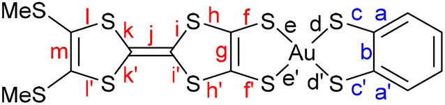
Comparison of the intramolecular bond distances of these complexes with those of the monoanionic species confirms the oxidized character of the complexes. As an illustrative example, Table 2 shows the bond distances for both anionic [Au(BMT-TTFS2)(bdt)]−1 and neutral [Au(BMT-TTFS2)(bdt)]˙ complexes (see Table S1 for other complexes). Largest variations occur essentially on the AuS2C2 metallacycles fused to the TTF core (f, f′ and g bonds). The shortening of the C–S (f, f′) bonds, together with a lengthening of the CC (g) bond is observed. These modifications are usually observed when oxidizing a monoanionic gold dithiolene complex to a neutral radical species. However, significant changes also occur in the TTF bond lengths, especially with a lengthening of the central CC (j) bond and a shortening of the (i, i′, j, j′) C–S bonds of the dithiole rings. These modifications are also traditionally observed when one goes from a neutral TTF to a cation radical, as illustrated in Table 2 between TMTTF0 and TMTTF+˙. These observations are in accordance with radical species delocalized on the overall TTF dithiolene ligand. Also, as shown in Table 2 and Table S1, the bond distances within the metallacycles on the pzdt and bdt side are almost unaffected when compared to those of the monoanionic species.
The paramagnetic nature of the three gold complexes, [Au(BMT-TTFS2)(bdt)]˙, [Au(BMT-TTFS2)(pzdt)]˙ and [Au(EDT-TTFS2)(bdt)]˙, was confirmed by EPR spectroscopy. The EPR experiments were performed at room temperature on polycrystalline samples collected at the anode after electrocrystallization. The spectra display slightly anisotropic signals around g ≈ 2 that are typical of an S = ½ system with rhombic g factors (Fig. 5, Table 3 and Fig. S7). The similarity in the EPR parameters of these three complexes indicates very common features of their electronic structure. The g tensor principal values are collected in Table 3 and compared with those reported for other radical gold bis(dithiolene) complexes.34,35 The absence of observable hyperfine coupling, very small anisotropy and g value close to that of an organic radical demonstrate that the spin density is delocalized on the dithiolene ligands with minimal contribution from the gold center, as usually observed for other radical gold bis(dithiolene) complexes.36,37 Note also that the Δg = gmax − gmin values (0.020–0.034) are the smallest ones observed among such radical gold complexes, indicating an extensive, if not exclusive, spin density concentration on the TTF core.
 | ||
| Fig. 5 X-band EPR spectrum of the polycrystalline sample of [Au(BMT-TTFS2)(bdt)]˙. | ||
| Compounds | g min | g int | g max | 〈gav〉 | g max–gmin | Ref. |
|---|---|---|---|---|---|---|
| [(BMT-TTFS2)Au(bdt)]˙ | 1.986 | 2.007 | 2.020 | 2.004 | 0.034 | This work |
| [(BMT-TTFS2)Au(pzdt)]˙ | 1.997 | 2.007 | 2.017 | 2.007 | 0.020 | This work |
| [EDT-TTFS2)Au(bdt)]˙ | 1.998 | 2.005 | 2.020 | 2.007 | 0.022 | This work |
| [Au(S2C2(C6H4-OC4H9)2]˙ | 1.945 | 2.026 | 2.059 | 2.010 | 0.114 | 34 |
| [Au(mnt)2]˙ | 1.928 | 2.039 | 2.075 | 2.014 | 0.147 | 36 |
Solid state properties
In the solid state, [Au(BMT-TTFS2)(bdt)]˙ complexes form stacks parallel to each other to give rise to layered materials (Fig. S8). Within these stacks, the complexes adopt a head-to-tail organization, with two different overlap patterns (Fig. 6), both characterized by a large longitudinal slip between neighboring complexes. The largest slip, with the gold atom above the most distant CC bond of the TTF moiety, is associated with the smallest S⋯S contacts (down to 3.33 Å) between TTF moieties, well below the S⋯S van der Waals contact distance. It is defined as the intra-dimer interaction (I), while the interdimer interaction (II) is characterized by closer proximity of the gold atoms but notably larger intermolecular S⋯S contacts (>3.46 Å).
 | ||
| Fig. 6 Detail of the stacking and the overlaps between neighboring complexes in [Au(BMT-TTFS2)(bdt)]˙. | ||
The [Au(BMT-TTFS2)(pzdt)]˙ complexes with the pzdt ligand also form stacks parallel to each other to give rise to layered materials (Fig. S8). Each stack is also dimerized with a head-to-tail organization of the complexes within the stacks (Fig. 7). Within the dimers (I), there is a longitudinal slip between neighboring complexes with the shortest S⋯S distance of 3.29 Å found for interaction I, while the overlap (II) between dimers is characterized by a lateral slip, with a notably larger plane-to-plane distance of 3.51 Å.
 | ||
| Fig. 7 Details of the overlaps between neighboring complexes in [Au(BMT-TTFS2)(pzdt)]˙. | ||
The overlap patterns for [Au(BMT-TTFS2)(bdt)]˙ and [Au(BMT-TTFS2)(pzdt)]˙ are totally different from those observed in the homoleptic, symmetric, TTF-based [Au(tmdt)2]˙ complex (cf.Scheme 1c) reported earlier.20 In the latter, a longitudinal slip between the closest complexes leads to a near-superposition of a TTF core from each neighboring complex (Fig. 8a), while the other overlap, with longitudinal and lateral slips, is also associated with a shorter plane-to-plane distance (Fig. 8b) and the occurrence of short lateral intermolecular contacts. For [Au(BMT-TTFS2)(bdt)]˙ and [Au(BMT-TTFS2)(pzdt)]˙, the structure appears to be more one-dimensional (see below).
 | ||
| Fig. 8 Details of the two different overlap patterns between neighboring complexes in [Au(tmdt)2]. | ||
The temperature and pressure dependence of the resistivity of both crystalline complexes [Au(BMT-TTFS2)(bdt)]˙ and [Au(BMT-TTFS2)(pzdt)]˙ was measured on single crystals by the four-points technique using a Diamond Anvil Cell (DAC). Both compounds exhibit semi-conducting behaviour with similar RT conductivities in the range of 10−4 S cm−1 (Fig. 9 and 10). The pressure dependence was determined for [Au(BMT-TTFS2)(bdt)]˙ up to 6.4 GPa as crystals show an abrupt transition to a less conducting state, with an activation energy increasing from 0.11 eV up to 0.27 eV at 2.6 GPa, to further decrease at higher pressures (Table S3). The pzdt analog [Au(BMT-TTFS2)(pzdt)]˙ exhibits a more regular behavior (Fig. 10), with an activation energy of 0.2 eV, which decreases under pressure, down to 0.023 eV at 21.1 GPa (Fig. S9 and Table S4).
 | ||
| Fig. 9 Temperature and pressure dependence of the resistivity of [Au(BMT-TTFS2)(bdt)]˙. | ||
 | ||
| Fig. 10 Temperature and pressure dependence of the resistivity of [Au(BMT-TTFS2)(pzdt)]˙. | ||
Electronic structures
Electronic localization in gold bis(dithiolene) [Au(dt)2]˙ complexes,12 which has a strong control of their chemical properties,13 is not a trivial question. It is now established that even when such complexes possess two chemically equivalent ligands, the electronic distribution, and most notably the unpaired electron, can be unevenly localized on the two ligands, particularly when the ligands lack extended delocalization. Recently, we have examined this question for mixed-ligand radical gold bis(dithiolene) [Au(dtA)(dtB)]˙ complexes, such as [Au(Et-thiazdt)(bdt)]−1,˙ (cf.Scheme 1b).13 Despite this dissymmetrization and its consequences on the molecular properties, the radical complexes adopted in the solid state a head-to-tail organization with limited overlap interactions within weakly dimerized chains and semi-conducting behavior associated with electron localization (Mott insulator). Consequently, the complexes described here, with two non-innocent dithiolene ligands, but one of them much more electron-rich than the other, offer a challenging situation to test the generality of our previous ideas and the consequences on the solid-state properties. We remind that in these complexes, the Au orbitals have a small contribution to the SOMO. Thus, as far as we deal with the properties of SOMO and SOMO−1, we should consider the complex as made from two almost independent ligand-localized orbitals with a weak mixing. As previously discussed,13 a necessary requirement for handling this problem is the use of a spin-polarized approach (Unrestricted Kohn–Sham (UKS) approach) and the explicit consideration of both the SOMO and SOMO−1 orbitals. We will concentrate on the following on the bdt complex [Au(BMT-TTFS2)(bdt)]˙, as an illustrative example.Shown in Fig. 11 are the optimized CC bond lengths g and b within the metallacycles with their evolution (Δ) with respect to the corresponding symmetric complexes, the spin density, and the spin-orbitals around the SOMO of the optimized structure for an isolated [Au(BMT-TTFS2)(bdt)]˙ radical. The purple numbers indicate the left/right percentage distribution (%) of the spin density or the electron distribution in each spin-orbital. The spin density is strongly localized on the (BMT-TTFS2) side, which suggests that this is the most electron-rich, donor side. The optimized CC b bond on the bdt side decreased with respect to that in the symmetrical neutral complex, whereas the opposite change was observed for the CC g bond on the (BMT-TTFS2) side, thus confirming that the latter plays the role of the donor side of the complex. Note that it is the variation of the CC distance with respect to the value in the symmetric complex that provides a reliable indication of the donor–acceptor character of the side. Another point should be discussed here since the g and b distances are practically identical. We had shown that the g–b difference was large (i.e. around 0.05 Å) when none of the two ligands was bearing a delocalized system, while this difference was very small (i.e. around 0.01–0.005 Å) when one of the two ligands had a delocalized system.13 In the present case, with delocalization possible on the two sides, the calculated difference is even smaller. Surprisingly, this is not the case for the experimentally determined bond lengths (b–g = 0.094 Å with b being larger). As will be discussed later, this is the result of the fact that in the crystal structure, the complexes are strongly dimerized and do not provide a good reference for analyzing the electronic distribution.
 | ||
| Fig. 11 [Au(BMT-TTFS2)(bdt)]˙ isolated complex: (a) optimized b and g CC bond lengths, (b) spin density, and (c) spin-orbitals around the SOMO. The pairs of purple numbers indicate the left/right distribution percentage (%) of the spin density in (b) or the electron distribution in each spin-orbital in (c). In (a), the values in parentheses are the bond length changes with respect to the corresponding symmetric complexes. | ||
Regarding the individual spin-orbitals, since the spin density (Fig. 11b) is more concentrated on the (BMT-TTFS2) side, it could naively be assumed that the SOMO should also be located on this side. However, as shown in Fig. 11c, this is not the case: the SOMO is more concentrated on the bdt side (∼60%). This apparent contradiction appears when considering a Restricted Kohn–Sham (RKS) approach. However, as mentioned above, this kind of approach is not valid for the problem at hand. Since electrons with the same spin tend to avoid each other more than electrons with opposite spin, in UKS calculations, the α electron of the SOMO−1 concentrates on the opposite donor side of the complex, while the β electron of the SOMO−1 mostly locates on the acceptor side. Such an electron distribution should reduce as much as possible the electronic repulsion between the three electrons in the SOMO and the SOMO−1 spin orbitals. It follows that the SOMO localizes on the most electron-rich side. Incidentally, note that since we are dealing with spin-polarized calculations, the energies of the two spin-orbitals corresponding to SOMO−1 in a UKS calculation differ significantly due to the different electron–electron repulsion felt by the α/β electrons, with the unpaired α electron occupying the SOMO. An alternative view relies on considering where the missing β electron would be found. In this case, the answer is straightforward: it should be on the BMTS-TTF2 side as reflected in the LUMO. Consequently, the spin density (excess of α electrons) should coincide with the deficiency of β electrons given by the LUMO.
We thus confirm that the main location of the SOMO and the shortened CC bond length with respect to the symmetrical complexes in such mixed-ligand gold bis(dithiolene) complexes is associated with the acceptor side of the complex, while the spin density localizes on the donor side. It thus follows that the oxidation from the monoanionic mixed-ligand complex should affect preferentially the more electron-rich electron-donating ligand side, while the second oxidation should be more concentrated on the less electron-rich ligand side, as discussed above from the electrochemical investigations. Another interesting yet unexpected feature of these mixed-ligand gold bis(dithiolene) is the occurrence of a strong optical absorption in the NIR, ascribed to a SOMO−1 → LUMO transition, and predicted to occur at a higher energy than those of the two corresponding symmetrical complexes.13 As shown in Fig. 12, this is exactly what happens for [Au(BMT-TTFS2)(bdt)]˙. Indeed, the experimental value of its NIR absorption, found at 1250 nm (vide infra) can be compared with that of the symmetric [Au(bdt)2]˙ complex, where it is observed at 1390 nm (Fig. S13 for [Au(BMT-TTFS2)(pzdt)]˙).
 | ||
| Fig. 12 [Au(BMT-TTFS2)(bdt)]˙ complex: SOMO, SOMO–1 and LUMO levels and first significant low energy transition (SOMO–1 → LUMO) as calculated by TDDFT for the asymmetric and the two associated symmetric complexes. Note that the energies of the β SOMO–1 levels of the three compounds have been aligned to obtain a clearer visual representation. | ||
Band structure of [Au(BMT-TTFS2)(bdt)]˙
The electronic structure around the Fermi level, which determines the transport properties of [Au(BMT-TTFS2)(bdt)]˙, is strongly based on the interaction between the SOMO of neighboring complexes. As shown in Fig. 13, the crystal structure of [Au(BMT-TTFS2)(bdt)]˙ is built from layers perpendicular to the c direction. These layers interact mostly through CH3⋯CH3 interactions of the complex donor sides and a single S⋯S contact per unit cell of 3.425 Å. Within the unit cell, there are many short S⋯S contacts from 3.332 to 3.965 Å. Consequently, it is expected that the solid may be a two-dimensional conductor. As shown in Fig. 13, the layers of [Au(BMT-TTFS2)(bdt)]˙ contain chains along the (a + b) direction. | ||
| Fig. 13 A layer in the crystal structure of [Au(BMT-TTFS2)(bdt)]˙, where the four different intermolecular interactions are shown. The S⋯S intermolecular contacts smaller than 3.8 Å in (a) are shown as broken blue lines. | ||
There are two intra-chain (I and II, see Fig. 6) and two inter-chain (III and IV) interactions. The prominent factor of the structure is the strong dimerization associated with interaction I. Because of the structural restrictions imposed by the bulky –SCH3 groups, the S⋯S contacts associated with interaction II are long [3.763 (×2), 3.795 (×2) and 3.875 Å (×2)] but those associated with interaction I are very short [3.335 (×2), 3.445 (×2), 3.555 Å (×2), 3.602 (×2) Å, 3.789 (×2) Å]. More importantly, the two sulfur atoms of the ten pairs of S⋯S contacts in interaction I are practically on top of each other (see Fig. 6) so that their pz orbitals make very strong σ-type interactions. In contrast, the orientation of the sulfur pz orbitals in the two complexes in interaction II is considerably less favorable; the number of S⋯S interactions is smaller, and the distances are considerably longer. Thus, the SOMO⋯SOMO interaction associated with II is substantially weaker than that associated with I. Consequently, when dealing with SOMO⋯SOMO interactions, one must conclude that the chains along the (a + b) direction are strongly dimerized. The lateral contacts associated with interactions III and especially IV are also weak because of both orientation and metric aspects of the S⋯S interactions. We thus conclude that the basic unit of the [Au(BMT-TTFS2)(bdt)]˙ crystal structure is dimer I. The bonding and antibonding combinations of the two SOMOs of the dimer will broaden into two bands because of interactions II, III and IV. However, since interaction I must be strong, the two bands are expected to be separated by an energy gap considerably larger than the dispersions of bands.
In view of the previous discussion of the localization in gold bis(dithiolene) complexes, we have calculated the band structure of the [Au(BMT-TTFS2)(bdt)]˙ solid using both spin-polarized and non-spin-polarized (i.e., assuming double occupation of the levels) approaches. The latter are shown in Fig. 14 (Fig. S14 for [Au(BMT-TTFS2)(pzdt)]˙). Note that the calculations have been performed using a non-conventional set of axes, a′ = (a + b), b′ = a and c′ = c, where a, b and c refer to the experimental structure, to facilitate the analysis. In that way, the energy dispersion along the lines Γ–X and Γ–Y mostly reflects intra and inter-chain interactions within the layer. As expected from the structural analysis, the highest occupied and lowest empty bands are separated by a large gap of around 0.6 eV. The lowest empty band is built from the antibonding combination of the two SOMOs of the dimer. The highest occupied band is based on a combination of the two SOMOs (and SOMO−1) of the dimer.
 | ||
| Fig. 14 Calculated band structure for: (a) 3D [Au(BMT-TTFS2)(bdt)]˙ and (b) an isolated [Au(BMT-TTFS2)(bdt)]˙ chain assuming double occupation of the levels. The 3D calculation used a system of axes with a′ = (a + b), b′ = a and c′ = c, where a, b and c refer to the experimental structure. The dashed line refers to the highest occupied level and Γ = (0, 0, 0), X = (a′*/2, 0, 0), Y = (0, b′*/2, 0), M = (a′*/2, b′*/2, 0) and Z = (0, 0, c′*/2), respectively. | ||
Since the [Au(BMT-TTFS2)(bdt)]˙ complex requires a spin-polarized description of its electronic structure, it is necessary to consider if there are spin-polarized descriptions of the solid state that are more stable than that shown in Fig. 14a. To begin with, we have considered separately the four different interactions of the layer. When forcing the spin state of the dimeric unit in order to force localized orbitals on each complex, we found the following results. First, it is not possible to obtain an antiferromagnetic solution for interaction I; the calculation always converges to a solution with two paired and delocalized electrons. Second, the difference between the singlet and triplet states for interaction I is very large (∼0.41 eV), indicating that any possible localized states for the dimeric unit I should be very high in energy compared with the situation with paired electrons. Third, a very small antiferromagnetic exchange coupling is found for interactions II, III and IV (<7 meV per dimeric unit). Consequently, these interactions would only provide weak stabilization to a hypothetical solution with a localized electron in each SOMO, and thus, it would not be able to override the strong stabilization afforded by the electron pairing within dimer I. We then carried out the same type of calculations for the full solid-state structure and found that the non-spin-polarized (i.e., with all electrons paired) solution shown in Fig. 14a is by far the most stable. The energy difference with hypothetical localized descriptions is very large (∼0.5 eV per dimeric unit). We thus conclude that the band structure of Fig. 14a provides the correct description of the electronic structure of crystalline [Au(BMT-TTFS2)(bdt)]˙.
According to Fig. 14a, it is clear that the inter-layer interactions (see the Γ–Z line) are almost nil, as expected. Shown in Fig. 14b is the band structure for an isolated [Au(BMT-TTFS2)(bdt)]˙ chain along (a + b). The band gap is very similar to that of the full solid because it is primarily determined by dimerization. However, the nature of the bands is quite different from those along the Γ–X line in Fig. 14a, describing the intra-chain interactions in the solid. This means that inter-chain interactions are at work and influence the shape of the bands. In fact, the band dispersion along the lines representing the intra- and inter-chain interactions, Γ–X and Γ–Y respectively, are not very different. However, both dispersions are small with respect to the band gap, so that the conductivity is largely determined by strong dimerization in the solid. We thus conclude that [Au(BMT-TTFS2)(bdt)]˙ is a semiconductor with a large band gap dominated by the presence of strong dimers, making relatively weak interactions along the a and b directions. Since dimerization is strong, it is expected that the activated behavior will be maintained under pressure, as indeed experimentally observed (cf.Fig. 9 and 10).
Finally, we discuss the apparent contradiction between theoretical and experimental results concerning the structural symmetry vs asymmetry of a non-dimerized [Au(BMT-TTFS2)(bdt)]˙ complex. A single complex requires a spin-polarized description because of: (i) the existence of non-paired electrons and (ii) the fact that the Au orbitals have a very small participation in the SOMO, so that the complex should be considered as made from two almost independent ligand-localized orbitals with a weak mixing. To understand the nature of the spin density in this type of radical, it is mandatory to consider spin polarization effects in the SOMO and SOMO−1, which are all ligand-based π-type orbitals built from the same orbitals, the HOMO of the two dithiolene ligands. However, here, strong dimerization completely overrides the energy gain due to the optimization of electron repulsions in a hypothetical localized solid-state description. As discussed above, the dimerization is very strong (see Fig. 6) because the BMT-TTFS2 sides of the two complexes are on top of each other in the dimer, thus forming six very strong S⋯S σ-type interactions. In order to make such interactions as strong as possible when two complexes come together in the solid, they tend to concentrate as much as possible on SOMO, which initially is more concentrated on the [bdt] side, towards the BMT-TTFS2 side. Since the SOMO is bonding in both the g and b CC bonds (see Fig. 11), the electronic shift decreases the bonding character of b and increases the bonding character of g. This is the driving force behind the strong electronic rearrangement leading to electron pairing and a larger CC b bond on the bdt side. The important message of this analysis is that the structural details of the gold bis(dithiolene) complexes should be taken as indicative of the symmetry vs. asymmetry of the electronic structure only when the complex is structurally independent in the solid state.
Conclusions
In conclusion, we reported the synthesis of three neutral mixed-ligand gold bis(dithiolene) complexes, featuring ligands with different electronic distributions: one TTF dithiolate considered a highly electron-rich ligand and either a benzene or a pyrazine dithiolate. The different electronic properties between these two dithiolene ligands lead to an exacerbated spin density localization on the TTF ligand, with the resulting SOMO localized on the less electron-rich ligand. Notwithstanding their insolubility and tendency to precipitate at the electrode during spectroelectrochemical investigations, these neutral complexes exhibit strong optical absorption in the NIR, which lies outside the range of the parent symmetric complexes, at higher energy, an attractive possibility for modifying the NIR absorption of homoleptic complexes. The dissymmetry imposed by the presence of two different ligands leads to a head-to-tail arrangement in the solid state. The solid-state properties of radical complexes [Au(BMT-TTFS2)(bdt)]˙ and [Au(BMT-TTFS2)(pzdt)]˙, well explained by band structure calculations, are the consequence of a strong 1D electronic structure with strongly dimerized chains and a direct and large band gap, explaining the observed semiconducting behavior. At variance with weak dimerized systems adopting a Mott insulator behavior sensitive to pressure effects (toward a metallic state),7 [Au(BMT-TTFS2)(bdt)]˙ and [Au(BMT-TTFS2)(pzdt)]˙ show a robust gap under pressure, a direct consequence of the reinforced dimerization of BMT-TTFS2 moieties in the solid state. This work also opens perspectives for the elaboration of novel single-component conductors in which two different TTF dithiolate ligands could be organized around the gold atom, offering endless possibilities to challenge the prototypical [Au(tmdt)2] reported earlier.Experimental section
Materials and methods
Chemicals and materials from commercial sources were used without further purification. All the reactions were performed under an argon atmosphere. NMR spectra were obtained in CDCl3 unless indicated otherwise. Chemical shifts are reported in ppm; 1H NMR spectra were referenced to residual CHCl3 (7.26 ppm) and 13C NMR spectra were referenced to CHCl3 (77.2 ppm). Melting points were measured on a Kofler hot-stage apparatus and are uncorrected. Mass spectra were recorded at the Centre Régional de Mesures Physiques de l'Ouest, Rennes. Methanol, acetonitrile and dichloromethane were dried using an inert pure solvent column device. Cyclic voltammetry was performed in a three-electrode cell equipped with a platinum disk working electrode and a glassy carbon as a counter electrode. CVs were carried out on a 10−3 M solution of complex in CH2Cl2 and in CH2Cl2 with 0.1 M [Bu4N][PF6]. Potentials were measured versus a saturated calomel electrode (SCE). The spectroelectrochemical setup was performed in 0.2 M CH2Cl2-[NBu4][PF6] using a Pt grid as the working electrode, a Pt wire as the counter electrode and SCE reference electrode. A Shimadzu 3600 plus spectrophotometer was used to record the UV-vis-NIR spectra.Synthesis of [Bu4N][Au(BMT-TTFS2)(bdt)]
Under an inert atmosphere, 1,8-diazabicyclo[5.4.0]undec-7-ene (DBU) (0.55 ml, 5.5 mmol) was added to a solution of the gold complex27 [Bu4N][Au(bdt)Cl2] (180 mg, 0.27 mmol) and the proligand28 BMT-TTF(SCH2CH2CN)21 (126 mg, 0.27 mmol) in 10 ml of dried CH2Cl2. The addition of DBU generates a rapid color change from dark green to a light brown solution. After stirring for 21 h at room temperature, water was added to the reaction mixture, and the organic phase was washed with water several times and dried over MgSO4. The solvent was removed under vacuum and acetonitrile was added to precipitate the insoluble material; the precipitate was filtered off and the filtrate was concentrated. The crude product was dissolved in 1 ml CH2Cl2 and the product was precipitated by the addition of diethyl ether. The complex was recrystallized in MeOH to afford the salt [Bu4N][Au(BMT-TTFS2)(bdt)] as brown crystals in 75% yield. MP = 113 °C. 1H NMR (300 MHz, chloroform-d) δ 7.12 (dd, J = 6.0, 3.2 Hz, 2H), 6.85 (dd, J = 6.0, 3.3 Hz, 2H), 3.18–3.07 (m, 10H), 2.41 (s, 6H), 1.38 (h, J = 7.2 Hz, 10H), 0.95 (t, J = 7.2 Hz, 12H). 13C NMR (75 MHz, chloroform-d) δ 140.84, 127.67, 127.31, 123.78, 58.84, 24.11, 19.72, 19.14, 13.75. Elem. anal. calcd for C30H46AuNS10: C, 38.40; H, 4.94; N, 1.49. Found: C, 38.25; H, 4.96; N, 1.67.Synthesis of [Bu4N][Au(EDT-TTFS2)(bdt)]
Under an inert atmosphere, 1,8-diazabicyclo[5.4.0]undec-7-ene (DBU) (0.45 ml, 3 mmol) was added to a solution of the gold complex27 [Bu4N][Au(bdt)Cl2] (100 mg, 0.15 mmol) and the proligand28 EDT-TTF(SCH2CH2CN)22 (71 mg, 0.15 mmol) in 10 ml of dried CH2Cl2. The addition of DBU generates a rapid color change from a dark to a light brown solution. After stirring for 21 h at room temperature, water was added to the reaction mixture, and the organic phase was washed with water several times and dried over MgSO4. The solvent was removed under vacuum, and acetonitrile was added to precipitate the insoluble material; the precipitate was filtered off, and the filtrate was concentrated. The crude product was dissolved in 1 ml CH2Cl2, and the product was precipitated by the addition of diethyl ether. The complex was recrystallized in a mixture of MeOH/DCM to afford the salt [Bu4N][Au(EDT-TTFS2)(bdt)] as pink crystals in 41% yield. MP = 130 °C. 1H NMR (400 MHz, CDCl3) δ 7.13 (dd, J = 6.0, 3.2 Hz, 2H), 6.85 (dd, J = 6.0, 3.3 Hz, 2H), 3.27 (s, 4H), 3.24–3.16 (m, 8H), 1.41 (h, J = 7.3 Hz, 8H), 0.98 (t, J = 7.3 Hz, 12H). 13C NMR (75 MHz, CD3CN) δ 141.69, 128.36, 128.93, 124.80, 59.36, 31.00, 24.33, 20.34, 13.76; elem. anal. calcd for C30H44AuNS10: C, 38.48; H, 4.74; N, 1.50. Found: C, 38.81; H, 4.16; N, 1.13.Synthesis of [Bu4N][Au(BMT-TTFS2)(pzdt)]
Under an inert atmosphere, 1,8-diazabicyclo[5.4.0]undec-7-ene (DBU) (0.4 ml, 2.7 mmol) was added to a solution of the gold complex13 [Bu4N][Au(pzdt)Cl2] (100 mg, 0.14 mmol) and the proligand28 BMT-TTF(SCH2CH2CN)21 (63 mg, 0.14mmol) in 10 ml of dried CH2Cl2. The addition of DBU generates a rapid color change from green to a dark brown solution. After stirring for 21 h at room temperature, water was added to the reaction mixture, and the organic phase was washed with water several times and dried over MgSO4. The solvent was removed under vacuum and acetonitrile was added to precipitate the insoluble material; the precipitate was filtered off and the filtrate was concentrated. The crude product was dissolved in 1 ml CH2Cl2 and the product was precipitated by the addition of diethyl ether. The complex was recrystallized in MeCN to afford the salt [Bu4N][Au(BMT-TTFS2)(pzdt)] as brown crystals in 43% yield. MP = 44 °C. 1H NMR (300 MHz, Chloroform-d) δ 7.96 (d, J = 2.4 Hz, 2H), 3.24–3.12 (m, 10H), 2.44 (s, 6H), 1.43 (h, J = 7.2 Hz, 10H), 1.00 (t, J = 7.3 Hz, 15H).13C NMR (75 MHz, CDCl3) δ 158.71, 136.27, 136.03, 127.31, 77.42, 77.21, 77.00, 76.58, 59.00, 24.12, 19.79, 19.12, 13.73. Elem. anal. calcd for C28H44AuN3S10(CH2Cl2)0.5: C, 34.83; H, 4.62; N, 4.28. Found: C, 35.14; H, 4.26; N, 4.38.X-ray crystallography
Suitable crystals for single-crystal X-ray diffraction experiments were selected and mounted with a cryoloop on the goniometer head of a D8 Venture Bruker-AXS diffractometer equipped with a CMOS-PHOTON70 detector, using Mo-Kα radiation (λ = 0.71073 Å multilayer monochromator). Crystal structures were solved by the dual-space algorithm using the SHELXT program,38 and then refined with full-matrix least-squares methods based on F2 (SHELXL).39 All non-hydrogen atoms were refined with anisotropic atomic displacement parameters. H atoms were finally included in their calculated positions and treated as riding on their parent atom with constrained thermal parameters. Details of the final refinements are summarized in Table S2 in SI. The supplementary crystallographic data for this study are provided in CCDC 2474551–2474556.Computational details
The DFT calculations for isolated complexes were performed with the Gaussian 16 program40 using the hybrid BLYP35 functional proposed by Kaupp et al.,41 together with the D95(d,p) double-zeta basis set42 for main-group elements and the Stuttgart Dresden effective core potentials43 for Au. The structure of the isolated complexes was optimized. The first-principles calculations for the solid were carried out using a numeric atomic orbital density functional theory (DFT) approach44,45 developed for efficient calculations in large systems and implemented in the SIESTA code.46–49 We used the generalized gradient approximation (GGA) to DFT, in particular, the Perdew, Burke, and Ernzerhof functional.50 To study the relative energies of states with localized electrons, spin-polarized band calculations were performed for appropriate supercells. All calculations included a Hubbard correction term Ueff = U − J = 6.0 eV for the S 3p states.51 In a previous work,52 we found that this U term on the chalcogen atoms is needed to appropriately describe the electronic structure of molecular conductors, for which accurate experimental information on the bandwidth and charge-transfer is available. Only the valence electrons are considered in the calculation, with the core replaced by norm-conserving scalar-relativistic pseudopotentials53 factorized in the Kleinman–Bylander form.54 We used a split-valence double-ζ basis set, including polarization orbitals with an energy shift of 10 meV for S, C and H atoms.55 For gold atoms, we used a split-valence basis set with double-ζ plus polarization, where the 5d electrons of Au were also treated as valence electrons. The basis functions used for Au have been optimized to reproduce the geometry and the bulk modulus for the ccp crystal structure of metallic gold.56 The energy cutoff of the real-space integration mesh was 300 Ry. The Brillouin zone was sampled using a grid of (20 × 20 × 3) k-points.57 The crystal structure at 150 K was used for solid-state computations.Conflicts of interest
The authors declare no conflict of interest.Data availability
The data supporting this article have been included as part of the supplementary information (SI). Supplementary information: Tables S1–S5 and Fig. S1–S14. See DOI: https://doi.org/10.1039/d5ma00996k.CCDC 2474551 ([Bu4N][Au(BMT-TTFS2)(bdt)]), 2474552 ([Bu4N][Au(EDT-TTFS2)(bdt)]), 2474553 ([Bu4N][Au(BMT-TTFS2)(pzdt)]), 2474554 ([Au(BMT-TTFS2)(pzdt)]˙), 2474555 ([Au(BMT-TTFS2)(bdt)]˙), 2474556 ((n-Bu4N)(TCNQ)3]) contain the supplementary crystallographic data for this paper.58a–e
Acknowledgements
Work in France was supported by the ANR under contract no. ANR-23-CE07-0032-01 and by Rennes University through a PhD grant (to H. K.). Work in Spain was supported by MCIN/AEI/10.13039/501100011033 and AEI through Grants PID2022-139776NB-C61 and PID2021-128217NB-I00 and by Generalitat de Catalunya (2021SGR01519 and 2021SGR00286). E. C. acknowledges MCIN/AEI/10.13039/501100011033 and AEI for support through the Severo Ochoa FUNFUTURE MaTrans42 (CEX2023-0001263-S) Excellence Centre distinction. P. A. acknowledges MCIN/AEI/10.13039/501100011033 and AEI for support through the Maria de Maeztu Units of Excellence Program (CEX-2021-001202-M). The work at SNU was supported by the National Research Foundation (RS-2024-00338707) and by the Ministry of Education through the core center program (2021R1A6C101B418).References
- N. C. Schiødt, T. Bjørnholm, K. Bechgaard, J. J. Neumeier, C. Allgeier, C. S. Jacobsen and N. Thorup, Phys. Rev. B: Condens. Matter Mater. Phys., 1996, 53, 1773–1778 CrossRef.
- D. Belo, H. Alves, E. B. Lopes, M. T. Duarte, V. Gama, R. T. Henriques, M. Almeida, A. Pérez-Benítez, C. Rovira and J. Veciana, Chem. – Eur. J., 2001, 7, 511–519 CrossRef CAS.
- O. J. Dautel, M. Fourmigue, E. Canadell and P. Auban-Senzier, Adv. Funct. Mater., 2002, 12, 693–698 CrossRef CAS.
- M. F. G. Velho, R. A. L. Silva, G. Brotas, E. B. Lopes, I. C. Santos, A. Charas, D. Belo and M. Almeida, Dalton Trans., 2020, 49, 13737–13743 RSC.
- A. I. S. Neves, I. C. Santos, J. T. Coutinho, L. C. J. Pereira, R. T. Henriques, E. B. Lopes, H. Alves, M. Almeida and D. Belo, Eur. J. Inorg. Chem., 2014, 3989–3999 CrossRef CAS.
- A. Filatre-Furcate, T. Roisnel, M. Fourmigué, N. Bellec, P. Auban-Senzier and D. Lorcy, Chem. – Eur. J., 2017, 23, 16004–16013 CrossRef CAS PubMed.
- N. Tenn, N. Bellec, O. Jeannin, L. Piekara-Sady, P. Auban-Senzier, J. Íñiguez, E. Canadell and D. Lorcy, J. Am. Chem. Soc., 2009, 131, 16961–16967 CrossRef CAS PubMed.
- G. Yzambart, N. Bellec, G. Nasser, O. Jeannin, M. Fourmigué, P. Auban-Senzier, J. Íñiguez, E. Canadell and D. Lorcy, J. Am. Chem. Soc., 2012, 134, 17138–17148 CrossRef CAS.
- Y. Le Gal, T. Roisnel, P. Auban-Senzier, N. Bellec, J. Íñiguez, E. Canadell and D. Lorcy, J. Am. Chem. Soc., 2018, 140, 6998–7004 CrossRef CAS.
- M. M. Andrade, R. A. L. Silva, I. C. Santos, E. B. Lopes, S. Rabaça, L. C. J. Pereira, J. T. Coutinho, J. P. Telo, C. Rovira, M. Almeida and D. Belo, Inorg. Chem. Front., 2017, 4, 270–280 RSC.
- A. J. Schultz, H. H. Wang, L. C. Soderholm, T. L. Sifter, J. M. Williams, K. Bechgaard and M.-H. Whangbo, Inorg. Chem., 1987, 26, 3757–3761 CrossRef CAS.
- D. G. Branzea, F. Pop, P. Auban-Senzier, R. Clérac, P. Alemany, E. Canadell and N. Avarvari, J. Am. Chem. Soc., 2016, 138, 6838–6851 CrossRef CAS.
- H. Kharraz, P. Alemany, E. Canadell, Y. Le Gal, T. Roisnel, H. Cui, K. H. Kim, M. Fourmigué and D. Lorcy, Chem. Sci., 2024, 15, 11604–11616 RSC.
- M. Nakano, A. Kuroda, T. Maikawa and G. E. Matsubayashi, Mol. Cryst. Liq. Cryst., 1996, 284, 301–305 CrossRef CAS.
- M. Nakano, A. Kuroda and G.-E. Matsubayashi, Inorg. Chim. Acta, 1997, 254, 189–193 CrossRef CAS.
- K. Ueda, M. Goto, T. Sugimoto, S. Endo, N. Toyota, K. Yamamoto and H. Fujita, Synth. Metals, 1997, 85, 1679 CrossRef CAS.
- Y. Misaki, Y. Tani, M. Taniguchi, T. Maitani, K. Tanaka and K. Bechgaard, Mol. Cryst. Liq. Cryst., 2000, 343, 59–64 CrossRef CAS.
- W. Susuki, E. Fujiwara, A. Kobayashi, Y. Fujishiro, E. Nishibori, M. Takata, M. Sakata, H. Fujiwara and H. Kobayashi, J. Am. Chem. Soc., 2003, 125, 1486–1487 CrossRef PubMed.
- B. Zhou, M. Shimamura, E. Fujiwara, A. Kobayashi, T. Higashi, E. Nishibori, M. Sakata, H. Cui, K. Takahashi and H. Kobayashi, J. Am. Chem. Soc., 2006, 128, 3872–3873 CrossRef CAS.
- Y. Okano, B. Zhou, M. Tanaka, M. Adachi, Y. Ohishi, M. Takata, S. Aoyagi, E. Nishibori, M. Sakata, A. Kobayashi and H. Kobayashi, J. Am. Chem. Soc., 2009, 131, 7169–7174 CrossRef CAS.
- M. Sasa, E. Fujiwara, A. Kobayashi, S. Ishibashi, K. Terakura, Y. Okano, H. Fujiwara and H. Kobayashi, J. Mater. Chem., 2005, 15, 155–163 RSC.
- K. Kubo, M. Nakano, H. Tamura, G.-E. Matsubayashi and M. Nakamoto, J. Organomet. Chem., 2003, 669, 141–148 CrossRef CAS.
- K. Kubo, A. Nakao, Y. Ishii, R. Kato and G.-E. Matsubayashi, Synth. Metals, 2005, 153, 425–428 CrossRef CAS.
- K. Kubo, A. Nakao, Y. Ishii, T. Yamamoto, M. Tamura, R. Kato, K. Yakushi and G.-E. Matsubayashi, Inorg. Chem., 2008, 47, 5495–5502 CrossRef CAS.
- S. Arata, Y. Kim, N. Hoshino, K. Tahara, K. Takahashi, T. Kadoya, T. Inoue, T. Nakamura, T. Akutagawa, J. Y. Yamada and K. Kubo, Eur. J. Inorg. Chem., 2023, e202300017 CrossRef CAS.
- R. Perochon, F. Barrière, O. Jeannin, L. Piekara-Sady and M. Fourmigué, Chem. Commun., 2021, 57, 1615–1618 RSC.
- M. Murata, S. Kaji, H. Nishimura, A. Wakamiya and Y. Murata, Eur. J. Inorg. Chem., 2016, 3228–3232 CrossRef CAS.
- N. Svenstrup, K. M. Rasmussen, T. K. Hansen and J. Becher, Synthesis, 1994, 809–812 CrossRef CAS.
- T. Suzuki, Y. Yamashita, C. Kabuto and T. Miyashi, J. Chem. Soc., Chem. Commun., 1989, 1102–1103 RSC.
- J. P. M. Nunes, M. J. Figueira, D. Belo, I. C. Santos, B. Ribeiro, E. B. Lopes, R. T. Henriques, J. Vidal-Gancedo, J. Veciana, C. Rovira and M. Almeida, Chem. – Eur. J., 2007, 13, 9841–9849 CrossRef CAS.
- H. Spanggaard, J. Prehn, M. B. Nielsen, E. Levillain, M. Allain and J. Becher, J. Am. Chem. Soc., 2000, 122, 9486–9494 CrossRef CAS.
- L. Wang, J. P. Zhang and B. Zhang, Acta Crystallogr., 2005, E61, 065–066 Search PubMed.
- H. Endres, Acta Crystallogr., 1987, C43, 439–441 CAS.
- R. Perochon, L. Piekara-Sady, W. Jurga, R. Clérac and M. Fourmigué, Dalton Trans., 2009, 3052–3061 RSC.
- R. Perochon, C. Poriel, O. Jeannin, L. Piekara-Sady and M. Fourmigué, Eur. J. Inorg. Chem., 2009, 5413–5421 CrossRef CAS.
- S. Kokatam, K. Ray, J. Pap, E. Bill, W. E. Geiger, R. J. LeSuer, P. H. Rieger, T. Weyhermüller, F. Neese and K. Wieghardt, Inorg. Chem., 2007, 46, 1100–1111 CrossRef CAS.
- K. Ray, T. Weyhermüller, A. Goossens, M. W. J. Craje and K. Wieghardt, Inorg. Chem., 2003, 42, 4082–4087 CrossRef CAS PubMed.
- G. M. Sheldrick, Acta Crystallogr., 2015, A71, 3–8 CrossRef PubMed.
- G. M. Sheldrick, Acta Crystallogr., 2015, C, 3–8 CrossRef PubMed.
- M. J. Frisch, G. W. Trucks, H. B. Schlegel, G. E. Scuseria, M. A. Robb, J. R. Cheeseman, G. Scalmani, V. Barone, G. A. Petersson, H. Nakatsuji, X. Li, M. Caricato, A. V. Marenich, J. Bloino, B. G. Janesko, R. Gomperts, B. Mennucci, H. P. Hratchian, J. V. Ortiz, A. F. Izmaylov, J. L. Sonnenberg, D. Williams-Young, F. Ding, F. Lipparini, F. Egidi, J. Goings, B. Peng, A. Petrone, T. Henderson, D. Ranasinghe, V. G. Zakrzewski, J. Gao, N. Rega, G. Zheng, W. Liang, M. Hada, M. Ehara, K. Toyota, R. Fukuda, J. Hasegawa, M. Ishida, T. Nakajima, Y. Honda, O. Kitao, H. Nakai, T. Vreven, K. Throssell, J. A. Montgomery, Jr., J. E. Peralta, F. Ogliaro, M. J. Bearpark, J. J. Heyd, E. N. Brothers, K. N. Kudin, V. N. Staroverov, T. A. Keith, R. Kobayashi, J. Normand, K. Raghavachari, A. P. Rendell, J. C. Burant, S. S. Iyengar, J. Tomasi, M. Cossi, J. M. Millam, M. Klene, C. Adamo, R. Cammi, J. W. Ochterski, R. L. Martin, K. Morokuma, O. Farkas, J. B. Foresman and D. J. Fox, Gaussian 16, Revision A.03, Gaussian, Inc., Wallingford CT, 2016 Search PubMed.
- M. Kaupp, M. Renz, M. Parthey, M. Stolte, F. Würthner and C. Lambert, Phys. Chem. Chem. Phys., 2011, 13, 16973–16986 RSC.
- T. H. Dunning Jr. and P. J. Hay, in Modern Theoretical Chemistry, ed. H. F. Schaefer III, vol. 3, Plenum, New York, 1977, pp. 1–28 Search PubMed.
- D. Andrae, U. Häußermann, M. Dolg, H. Stoll and H. Preuß, Theoret. Chim. Acta, 1990, 77, 123–141 CrossRef CAS.
- P. Hohenberg and W. Kohn, Phys. Rev., 1965, 136, B864–B871 CrossRef.
- W. Kohn and L. J. Sham, Phys. Rev., 1965, 140, A1133–A1138 CrossRef.
- J. M. Soler, E. Artacho, J. D. Gale, A. García, J. Junquera, P. Ordejón and D. Sánchez-Portal, J. Phys.: Condens. Matter, 2002, 14, 2745–2779 CrossRef CAS.
- E. Artacho, E. Anglada, O. Diéguez, J. D. Gale, A. García, J. Junquera, R. D. Martin, P. Ordejón, M. A. Pruneda, D. Sánchez-Portal and J. M. Soler, J. Phys.: Condens. Matter, 2008, 20, 064208 CrossRef PubMed.
- A. García, N. Papior, A. Akhtar, E. Artacho, V. Blum, E. Bosoni, P. Brandimarte, M. Brandbyge, J. I. Cerdá, F. Corsetti, R. Cuadrado, V. Dikan, J. Ferrer, J. D. Gale, P. García-Fernández, V. M. García-Suárez, V. M. García, G. Huhs, S. Illera, R. Korytar, P. Koval, I. Lebedeva, L. Lin, P. López-Tarifa, S. G. Mayo, S. Mohr, P. Ordejón, A. Postnikov, Y. Pouillon, M. A. Pruneda, R. Robles, D. Sánchez-Portal, J. M. Soler, R. Ullah, W.-Z. Yu and J. Junquera, SIESTA: Recent developments and applications, J. Chem. Phys., 2020, 152, 204108 CrossRef.
- For more information on the SIESTA code visit: https://siesta-project.org/siesta/.
- J. P. Perdew, K. Burke and M. Ernzerhof, Generalized Gradient Approximation Made Simple, Phys. Rev. Lett., 1966, 77, 3865–3868 CrossRef.
- S. L. Dudarev, G. A. Botton, S. Y. Savrasov, C. J. Humphreys and A. P. Sutton, Phys. Rev. B: Condens. Matter Mater. Phys., 1998, 57, 1505–1509 CrossRef CAS.
- Y. Kiyota, I.-R. Jeon, O. Jeannin, M. Beau, T. Kawamoto, P. Alemany, E. Canadell, T. Mori and M. Fourmigué, Phys. Chem. Chem. Phys., 2019, 21, 22639–22646 RSC.
- N. Troullier and J. L. Martins, Phys. Rev. B: Condens. Matter Mater. Phys., 1991, 43, 1993–2006 CrossRef CAS.
- L. Kleinman and D. M. Bylander, Phys. Rev. Lett., 1982, 48, 1425–1428 CrossRef CAS.
- E. Artacho, D. Sánchez-Portal, P. Ordejón, A. García and J. M. Soler, Phys. Stat. Sol., 1999, 215, 809–817 CrossRef CAS.
- P. Alemany, M. Llunell and E. Canadell, Theor. Chem. Acc., 2009, 123, 85–92 Search PubMed.
- H. J. Monkhorst and J. D. Pack, Phys. Rev. B: Condens. Matter Mater. Phys., 1976, 13, 5188–5192 CrossRef.
- (a) CCDC 2474551: Experimental Crystal Structure Determination, 2025 DOI:10.5517/ccdc.csd.cc2p1z7z, CCDC 2474552: Experimental Crystal Structure Determination, 2025 DOI:10.5517/ccdc.csd.cc2p1z80; (b) CCDC 2474553: Experimental Crystal Structure Determination, 2025 DOI:10.5517/ccdc.csd.cc2p1z91; (c) CCDC 2474554: Experimental Crystal Structure Determination, 2025 DOI:10.5517/ccdc.csd.cc2p1zb2; (d) CCDC 2474555: Experimental Crystal Structure Determination, 2025 DOI:10.5517/ccdc.csd.cc2p1zc3; (e) CCDC 2474556: Experimental Crystal Structure Determination, 2025 DOI:10.5517/ccdc.csd.cc2p1zd4.
| This journal is © The Royal Society of Chemistry 2026 |