DOI:
10.1039/D5MA00868A
(Paper)
Mater. Adv., 2026,
7, 1066-1088
Re-entrant structural phase transition and charge carrier conduction in La2−xSrxFeMnO6 solid solutions for electronic device applications
Received
8th August 2025
, Accepted 26th November 2025
First published on 15th December 2025
Abstract
This research explores the structural, dielectric, and electrical transport characteristics of polycrystalline La2−xSrxFeMnO6 compounds with varying strontium concentrations (x = 0.0, 0.1, 0.2, 0.5, 1.0, 1.5, and 2.0). These compounds were prepared through the solid-state reaction technique at high temperatures. Rietveld refinement of their XRD data confirms a re-entrant structural phase transition (cubic–rhombohedral–cubic) induced by Sr doping. The vibrational study of (Fe/Mn)O6 octahedra was carried out by Raman and FTIR spectroscopies. X-ray photoelectron spectroscopy (XPS) results demonstrated the presence of mixed valence oxidation states (+3 and +4) of Fe and Mn cations in the measured samples. The temperature-dependent resistivity data of these compounds have been explained by the long-range electron hopping and short-range polaron hopping conduction mechanisms at high- and low-temperature regions, respectively. Their dielectric constant (ε′) exhibits dispersion behavior, which is attributed to the Maxwell–Wagner interfacial polarization and hopping mechanism of charge carriers. The leakage current density has been explained on the basis of Ohmic conduction mechanism and space-charge-limited conduction (SCLC) mechanism. All these studied properties are strongly influenced by structural distortion-induced strain, oxygen vacancies, Schottky defects, and possible charge ordering. The low leakage current density of these materials with a high dielectric constant make them promising for application in electronic devices.
1. Introduction
Nowadays, advanced materials are becoming increasingly important in a broad range of electronic and energy storage applications. In the near future, the development of energy storage and memory devices is expected to rely on giant dielectric materials possessing high dielectric permittivity (ε′). Perovskite materials have attracted considerable attention as a class of functional advance materials in the mixed oxide family due to their structurally stable crystal lattice, high oxide ion conductivity, presence of oxygen vacancies, and excellent thermal and chemical stability. In recent years, perovskites have garnered significant interest due to their promising applications in catalysis,1,2 electrocatalysis,3 photocatalysis,4 supercapacitors,5 fuel cell electrodes,2,5 metal–air batteries,6 solar cells,2,5,7 high density data storage devices,8 magnetic memory devices,9 separation membranes,10 and sensors.2 Perovskite materials typically adopt the general chemical formula of ABO3, where A and B represent cations and ‘O’ denotes the oxygen anion. The A-site cation is usually an alkali metal, alkaline earth metal, or lanthanide, while the B-site cation is a transition metal with a 3d, 4d, or 5d electronic configuration. Partial substitution at the A and/or B sites enables tuning of the valence states of the cations and allows for the introduction of nonstoichiometry via cationic or anionic vacancies to maintain the overall charge neutrality. The remarkable multifunctional properties of perovskites are primarily attributed to their nonstoichiometry in both cationic and anionic sublattices, the presence of multiple oxidation states of metal ions, and structural distortions in the cation coordination environment.2 Researchers have identified advanced functional properties in modified perovskites, which were achieved by converting simple perovskite structures into more complex forms, such as double perovskites, thereby enhancing their overall performance and application potential. Double perovskites, which are commonly represented by the empirical formula A2BB′O6, are an extension of the traditional ABO3 perovskite structure. In this configuration, both the A-site and B-site cations serve as tunable host positions, providing a broad platform for structural and functional tuning across a wide range of applications. The incorporation of rare earth elements, alkali metals, and alkaline earth metals at the cationic sites of ordered double perovskites has led to significant enhancements in their structural, electronic, and functional properties.11,12 A-site cation substitutions significantly enhance the electrical, magnetic, optical, and dielectric properties of perovskites, as observed in NaLaMgWO6,13 CaMnFeNbO6,14etc. Similarly, B-site substitution and doping, such as Bi2FeMnO6,15 La2NiMnO6,16 and La2FeMnO6,17 perovskites have also attracted attention owing to their incredible physical properties.
Materials exhibiting high dielectric constants have attracted renewed interest over the past several decades due to their widespread applications in devices such as microwave filters, dynamic random-access memory, voltage-controlled oscillators, and telecommunication systems.18,19 Lead-containing dielectric and ferroelectric materials are highly toxic and environmentally harmful. Consequently, the development of lead-free materials with rich dielectric characteristics is the major requirement at present. In last few years, significant research has been dedicated to developing lead-free materials with high dielectric constants.17,19–22 Double perovskite materials have been extensively studied because of their diverse physical properties and potential for various multifunctional applications.17,22,23 The charge conduction and relaxation behavior in rare-earth-based polycrystalline perovskites are significantly affected by temperature. To ensure an efficient performance in electronic and energy storage devices, various electrical parameters must be carefully optimized across a broad range of frequencies and temperatures. La-based compounds with the general formula LaBO3 (where, B = Fe, Mn, Ni, Co, Cr, Sr, Al, etc.)24–26 have attracted significant attention due to their distinct catalytic,1,24,25 electrocatalytic,3,26 photocatalytic,4 magnetic,27–29 optical,27–29 electrical,27,29 and sensing28 properties. These properties are strongly dependent on parameters such as crystallinity, phase purity, particle size, and morphological characteristics. Additionally, the doping of metal ions with the +2 or +3 oxidation state into the LaBO3 lattice significantly influences their structural and other functional properties.24,27 In our earlier publication, an La2FeMnO6 (LFMO) double perovskite was successfully synthesized by the substitution of Mn into the Fe site of the LaFeO3 single perovskite using the solid-state reaction method. This method was chosen due to its cost-effectiveness, minimal instrumentation requirements, and ability to yield materials with high crystallinity, phase purity, and chemical homogeneity. Further, we also studied its physical properties, which make it suitable for various multifunctional potential applications.17 It exhibits a high dielectric constant (in the order of 103) accompanied by low energy loss at room temperature (RT). LFMO shows rich magnetic characteristics such as exchange bias, high Curie temperature, glassy transitions, and Griffiths phase due to disordering of FeO6 and MnO6 octahedra.30–32 Based on the above-discussed characteristics, it can be used in energy storage capacitor and spintronic devices.
The doping of alkaline earth metals and transition metals into the A and B sites of the LaFeO3 perovskite lattice has a remarkable impact on its electrical, dielectric, and magnetic properties.17,27,33,34 Recently, many experimental studies have been reported on the effect of Sr doping on the physical and physicochemical properties of perovskite materials.16,35–39 M. Qu et al.16 reported that the electronic structure of La2−xSrxNiMnO6 (0 ≤ x ≤ 1.0) can be effectively tuned to enhance its oxygen evolution reaction (OER) and oxygen reduction reaction (ORR) activities, facilitating the development of efficient bifunctional electrocatalysts. D. Chen et al.35 reported that Sr doping is an effective strategy for enhancing the performance of perovskite light-emitting diodes (PeLEDs). Z. Wei et al.36 reported that the introduction of Sr into La0.5Gd0.5Ba1−xSrxCo2O5+δ significantly enhances its performance as a cathode material for solid oxide fuel cell (SOFC) applications. M. Lamhani et al.37 synthesized the Ca1−xSrxMnO3−δ (0 ≤ x ≤ 1) compound and observed a structural transition from an orthorhombic phase (Pnma) to a hexagonal phase (P63/mmc) within the composition range of 0.50 < x ≤ 0.75, while for x = 0.50, this material exhibited a mixed-phase structure of both orthorhombic (Pnma) and hexagonal (P63/mmc) symmetries. Moreover, the incorporation of strontium dopants has led to an improvement in the thermoelectric power factor, and a significant reduction in electrical resistivity. K. Sultan et al.38 observed a decrease in the dielectric constant of Pr2−xSrxNiMnO6 (where, x = 0.0, 0.2, 0.4) with an increase in Sr concentration. N. Saadon et al.23 observed a reduction in the band gap energy of Sr2−xCaxNiWO6 (where, x = 0.00, 0.02, 0.04, 0.06) with an increase in Sr concentration as well as an increase in its dielectric constant (at low frequencies). S. Abass et al.39 reported that the degree of cationic disorder increases in Nd2−xSrxNiMnO6 (where, x = 0.0, 0.1, 0.3) with an increase in Sr concentration, resulting in an increase in its dielectric constant. T. Katheriya et al.40 reported that the Sr doping at the La-site effectively modulated the negative permittivity of La2NiO4.
Motivated by these previous studies, the present work investigates the effect of Sr2+ substitution at the A-site of the La2FeMnO6 double perovskite (DP) on its structural, dielectric, magnetic, and electrical transport properties. To the best of our knowledge, no prior studies have explored the impact of Sr substitution at the La-site on these properties of La2FeMnO6 DP. A series of La2−xSrxFeMnO6 (where x = 0.0, 0.1, 0.2, 0.5, 0.1, 1.5 and 2.0) compounds was synthesized via the standard solid-state reaction method without the presence of any impurity phases, and also observed to show a re-entrant cubic–rhombohedral–cubic structural phase transition. Further, other physical properties (dielectric, magnetic, and electrical transport) were studied to determine the potential of this series for application in electronic devices.
2. Experimental details
2.1 Synthesis method
A polycrystalline series of La2−xSrxFeMnO6 (where x = 0.0, 0.1, 0.2, 0.5, 1.0, 1.5, 2.0) compounds was synthesized using the standard solid-state reaction method.17,34 We employed high-purity La2O3 (purity 99.9%, HI media), SrCO3 (purity 99%, HI media), Fe2O3 (purity 98%, HI media), and MnO2 (purity 99%, HI media) chemicals as precursors according to their stoichiometry and ground using an agate mortar for 3 h. The ground powder was heated to 1200 °C at a rate of 5 °C per minute and held at 1200 °C for 24 h in a muffle furnace in an air atmosphere, and then allowed to cool to RT naturally. The obtained powder was reground and calcined at 1200 °C for 7 h. Then, the calcined powder was ground again to get a fine powder. The obtained fine powder was uniaxially pressed into 10 mm dies to make pellets using a hydraulic press at a pressure of 12 bar. The obtained pellets were sintered at 1250 °C for 5 h in air to make them hard for further measurements. The chemical reaction is expressed by the following equation:
| 2(2 − x)La2O3 + 4xSrCo3 + 2Fe2O3 + 4MnO2 → 4La2−xSrxFeMnO6 + 4xCO2(↑) + (1 − x)O2(↑) |
2.2 Characterization techniques
X-ray powder diffraction (XRD) patterns were recorded at RT to analyze the structural properties of the synthesized samples using Cu Kα radiation (λ = 1.5406 Å) (Model: Empyrean, Malvern Panalytical, UK). The detailed structural information of the prepared samples was obtained through Rietveld refinement of the XRD data using the Full Prof Suite software. Surface morphology and elemental analysis were investigated using a field emission scanning electron microscope (FESEM) (Model: Gemini 560, Carl Zeiss, Germany) with an attached EDS unit. Raman spectra were collected at RT using a Raman spectrometer (Model: WITec Alpha 300 RA, Germany) with an excitation source wavelength of 532 nm. Fourier transmission infrared (FT-IR) spectra were recorded in KBr mode at RT using an FT-IR spectrometer (Spectrum One, PerkinElmer Instrument, USA) with a resolution of 1 cm−1. X-ray photoelectron spectroscopy (XPS) measurements were performed to study the electronic structure using a monochromatic Al Kα X-ray source (1486.6 eV) with an energy resolution of 1 eV (Instrument model: PHI 5000 Versa Probe III, Japan). The setup included a pass energy of 100 eV, an R4000 VG Scientia analyzer, and an X-ray source operating at 450 W. The pressure inside the chamber was maintained at 4.48 × 10⁻¹⁰ mbar. Both sides of the pellet were polished uniformly with high quality conducting silver paste (Sigma Aldrich) for electrical measurements. Room temperature dielectric and impedance measurements were carried out using a LCR meter (Model: E4980A Precision, Agilent, USA) across the frequency range of 100 Hz to 2 MHz. Temperature-dependent DC resistivity and current–voltage (I–V) measurements were conducted using a source meter (Model: 2634B, Keithley, USA). Room temperature magnetic hysteresis loops were recorded using a vibrational sample magnetometer (VSM) (Model: EZ9, Microsense, USA).
3. Results and discussion
3.1 Structural analysis
Fig. 1(a) shows the XRD patterns of La2−xSrxFeMnO6 (where x = 0.0, 0.1, 0.2, 0.5, 0.1, 1.5 and 2.0) solid solutions at RT. The presence of sharp and many distinct diffraction peaks indicates their polycrystalline bulk nature. The diffraction peaks were indexed based on the JCPDS file (JCPDS Card # 01-078-4452) corresponding to the cubic phase with Pm![[3 with combining macron]](https://www.rsc.org/images/entities/char_0033_0304.gif) m space group. The XRD pattern of the undoped sample (x = 0.0) matched well with our earlier reported results.17,34 No impurity peak was observed for the synthesized samples within the detection limits of XRD analysis, demonstrating the high purity of the materials. Fig. 1(b) shows a magnified view of the diffraction peak positioned in the 2θ range of 32.2–33.10°. According to this figure, it can be observed that as the concentration of Sr2+ dopant increased, the diffraction peaks shifted towards lower 2θ values up to x = 0.2, and after that they split and shifted to the higher angle side. This splitting and shifting indicate a change in the phase and unit cell parameters, respectively. These changes are attributed to the substitution of the Sr2+ bivalent cation (r = 1.44 Å) for the trivalent La3+ cation (r = 1.36 Å) at the A-site of the LFMO compound. The XRD patterns for the x = 0.0, 0.1 and 0.2 samples show their cubic (single phase) perovskite structure. Further, in the case of the x = 0.5 and 1.0 samples, the most intense peak located at 2θ ∼ 32.3° split, which indicates that the symmetry of their crystal structure deviates from cubic. To gain a better understanding of the crystal structural of LSFMO, the experimental XRD patterns were refined through Rietveld refinement using the FULLPROF suite software with their appropriate phase along with space group, as shown in Fig. 1(c)–(f) for some selected samples (x = 0.0, 0.5, 1.0 and 0.2), respectively. The strong correlation between the experimental and calculated XRD patterns, along with the low value of the R-factors and χ2, indicates the good quality of the refinement. During the refinement process, careful attention was given to multiple parameters, including background correction, zero shift, sample displacement, atomic coordinates, thermal vibration factors, scale factor, lattice constants, FWHM, and peak shape parameters. The XRD patterns of the x = 0.0, 0.1, and 0.2 compositions were successfully refined with a disordered cubic structure (Pmm), while for x = 0.5, it is refined well with a disordered rhombohedral structure (Rc). Further, for the x = 1.0 and 1.5 compositions, the refinement shows the mixed contribution of both disordered cubic (Pmm) and disordered rhombohedral (Rc) phases. Furthermore, for x = 2.0, its XRD pattern was refined well with the cubic (Pmm) phases. Hence, it can be concluded that LFMO shows a re-entrant structural phase transition (cubic-rhombohedral-cubic) with Sr doping (substitution). The fractional atomic coordinates, occupancy, and other structural parameters of the La2−xSrxFeMnO6 (where x = 0.0, 0.1, 0.2, 1.5, and 2.0) compounds obtained from the Rietveld refinement are given in Table 1. Prior to this study, a lot of research has been done on A-site doped perovskites but it is limited to partial substitution.16,36,37,41 They observed various phase transitions but not a re-entrant structural phase transition. M. Qu et al.16 reported that the La2−xSrxNiMnO6 (0 ≤ x ≤ 1.0) perovskite crystallize into a rhombohedral structure with Rc symmetry, and a secondary phase was observed as rocksalt NiO, when the amount of Sr doping was x ≥ 0.8. Z. Wei et al.36 synthesized the La0.5Gd0.5Ba1−xSrxCo2O5+δ (LGBCOSr−x, x = 0–0.5) perovskite via the solid state reaction route and reported a structural phase transition from a double layered tetragonal phase to a single layered cubic phase with an increase in the Sr doping ratio. J. K. Murthy et al.41 observed a structural phase transition in La2−xSrxCoMnO6 (0 ≤ x ≤ 1.0) double perovskite from monoclinic to disordered rhombohedral (Rc) to mixed phase of disordered rhombohedral (Rc) and cubic (Fmm) symmetry with an increase in Sr amount. Moreover, for x > 1, they observed some impurity peaks corresponding to the Co3O4 and MnO2 phases.
m space group. The XRD pattern of the undoped sample (x = 0.0) matched well with our earlier reported results.17,34 No impurity peak was observed for the synthesized samples within the detection limits of XRD analysis, demonstrating the high purity of the materials. Fig. 1(b) shows a magnified view of the diffraction peak positioned in the 2θ range of 32.2–33.10°. According to this figure, it can be observed that as the concentration of Sr2+ dopant increased, the diffraction peaks shifted towards lower 2θ values up to x = 0.2, and after that they split and shifted to the higher angle side. This splitting and shifting indicate a change in the phase and unit cell parameters, respectively. These changes are attributed to the substitution of the Sr2+ bivalent cation (r = 1.44 Å) for the trivalent La3+ cation (r = 1.36 Å) at the A-site of the LFMO compound. The XRD patterns for the x = 0.0, 0.1 and 0.2 samples show their cubic (single phase) perovskite structure. Further, in the case of the x = 0.5 and 1.0 samples, the most intense peak located at 2θ ∼ 32.3° split, which indicates that the symmetry of their crystal structure deviates from cubic. To gain a better understanding of the crystal structural of LSFMO, the experimental XRD patterns were refined through Rietveld refinement using the FULLPROF suite software with their appropriate phase along with space group, as shown in Fig. 1(c)–(f) for some selected samples (x = 0.0, 0.5, 1.0 and 0.2), respectively. The strong correlation between the experimental and calculated XRD patterns, along with the low value of the R-factors and χ2, indicates the good quality of the refinement. During the refinement process, careful attention was given to multiple parameters, including background correction, zero shift, sample displacement, atomic coordinates, thermal vibration factors, scale factor, lattice constants, FWHM, and peak shape parameters. The XRD patterns of the x = 0.0, 0.1, and 0.2 compositions were successfully refined with a disordered cubic structure (Pmm), while for x = 0.5, it is refined well with a disordered rhombohedral structure (Rc). Further, for the x = 1.0 and 1.5 compositions, the refinement shows the mixed contribution of both disordered cubic (Pmm) and disordered rhombohedral (Rc) phases. Furthermore, for x = 2.0, its XRD pattern was refined well with the cubic (Pmm) phases. Hence, it can be concluded that LFMO shows a re-entrant structural phase transition (cubic-rhombohedral-cubic) with Sr doping (substitution). The fractional atomic coordinates, occupancy, and other structural parameters of the La2−xSrxFeMnO6 (where x = 0.0, 0.1, 0.2, 1.5, and 2.0) compounds obtained from the Rietveld refinement are given in Table 1. Prior to this study, a lot of research has been done on A-site doped perovskites but it is limited to partial substitution.16,36,37,41 They observed various phase transitions but not a re-entrant structural phase transition. M. Qu et al.16 reported that the La2−xSrxNiMnO6 (0 ≤ x ≤ 1.0) perovskite crystallize into a rhombohedral structure with Rc symmetry, and a secondary phase was observed as rocksalt NiO, when the amount of Sr doping was x ≥ 0.8. Z. Wei et al.36 synthesized the La0.5Gd0.5Ba1−xSrxCo2O5+δ (LGBCOSr−x, x = 0–0.5) perovskite via the solid state reaction route and reported a structural phase transition from a double layered tetragonal phase to a single layered cubic phase with an increase in the Sr doping ratio. J. K. Murthy et al.41 observed a structural phase transition in La2−xSrxCoMnO6 (0 ≤ x ≤ 1.0) double perovskite from monoclinic to disordered rhombohedral (Rc) to mixed phase of disordered rhombohedral (Rc) and cubic (Fmm) symmetry with an increase in Sr amount. Moreover, for x > 1, they observed some impurity peaks corresponding to the Co3O4 and MnO2 phases.
 |
| | Fig. 1 (a) X-ray diffraction patterns of La2−xSrxFeMnO6 (where x = 0.0, 0.1, 0.2, 0.5, 1.0, 1.5, and 2.0) and (b) enlarged view of the most intense peak corresponding to the (110) plane. (c)–(f) Rietveld refinement for the x = 0.0, 0.5, 1.0, and 2.0 samples, respectively. | |
Table 1 Structural parameters obtained from the Rietveld refinement of the La2−xSrxFeMnO6 (where x = 0.0, 0.1, 0.2, 0.5, 1.0, 1.5, and 2.0) DPs
| Crystallographic parameters |
x = 0.0 |
x = 0.1 |
x = 0.2 |
x = 0.5 |
x = 1.0 |
x = 1.5 |
x = 2.0 |
| Crystal structure |
Cubic |
Cubic |
Cubic |
Rhombohedral |
Rhombohedral + Cubic |
Rhombohedral + Cubic |
Cubic |
| Space group |
Pmm |
Pmm |
Pmm |
Rc |
Rc (42%) + Pmm (58%) |
Rc (14%) + Pmm (86%) |
Pmm |
|
|
| Lattice parameters |
|
a (Å) |
3.9065 ± 8.0 × 10⁻⁴ |
3.9080 ± 7.8 × 10⁻⁴ |
3.9056 ± 8.2 × 10⁻⁴ |
5.5218 ± 7.5 × 10⁻⁴ |
(5.4602 ± 6.9 × 10⁻⁴) + (3.8962 ± 7.5 × 10⁻⁴) |
(5.5216 ± 7.2 × 10⁻⁴) + (3.8541 ± 8.1 × 10⁻⁴) |
3.8552 ± 6.4 × 10⁻⁴ |
|
b (Å) |
3.9065 ± 8.0 × 10⁻⁴ |
3.9080 ± 7.8 × 10⁻⁴ |
3.9056 ± 8.2 × 10⁻⁴ |
5.5218 ± 7.5 × 10⁻⁴ |
(5.4602 ± 6.9 × 10⁻⁴) + (3.8962 ± 7.5 × 10⁻⁴) |
(5.5216 ± 7.2 × 10⁻⁴) + (3.8541 ± 8.1 × 10⁻⁴) |
3.8552 ± 6.4 × 10⁻⁴ |
|
c (Å) |
3.9065 ± 8.0 × 10⁻⁴ |
3.9080 ± 7.8 × 10⁻⁴ |
3.9056 ± 8.2 × 10⁻⁴ |
13.3837 ± 8.4 × 10⁻⁴ |
(13.3718 ± 8.1 × 10⁻⁴) + (3.8962 ± 7.5 × 10⁻⁴) |
(13.3837 ± 7.2 × 10⁻⁴) + (3.8541 ± 8.1 × 10⁻⁴) |
3.8552 ± 6.4 × 10⁻⁴ |
|
V (Å3) |
59.616 ± 3.67 × 10⁻² |
59.683 ± 3.75 × 10⁻² |
59.574 ± 3.84 × 10⁻² |
353.40 ± 10.9 × 10⁻² |
(345.25 ± 10.1 × 10⁻²) + (59.14 ± 4.0 × 10⁻²) |
(353.37 ± 8.7 × 10⁻²) + (57.24 ± 4.0 × 10⁻²) |
57.30 ± 2.67 × 10⁻² |
|
α, β, and γ (°) |
α = β = γ = 90 |
α = β = γ = 90 |
α = β = γ = 90 |
α = β = 90 and γ = 120 |
α = β = 90 & γ = 120 + α = β = γ = 90 |
α = β = 90 & γ = 120 + α = β = γ = 90 |
α = β = γ = 90 |
|
|
| Atomic position |
| La/Sr |
|
x
|
0.00 |
0.00 |
0.00 |
0.00 |
0.00 + 0.00 |
0.00 + 0.00 |
0.00 |
|
y
|
0.00 |
0.00 |
0.00 |
0.00 |
0.00 + 0.00 |
0.00 + 0.00 |
0.00 |
|
z
|
0.00 |
0.00 |
0.00 |
0.25 |
0.25 + 0.00 |
0.25 + 0.00 |
0.00 |
| Occupancy |
1.0/0.0 |
0.95/0.05 |
0.90/0.10 |
0.72/0.22 |
0.50/0.50 + 0.52/0.50 |
0.27/0.73 + 0.25/0.75 |
0.0/0.1 |
|
|
| Mn/Fe |
|
x
|
0.50 |
0.50 |
0.50 |
0.00 |
0.00 + 0.50 |
0.00 + 0.50 |
0.50 |
|
y
|
0.50 |
0.50 |
0.50 |
0.00 |
0.00 + 0.50 |
0.00 + 0.50 |
0.50 |
|
z
|
0.50 |
0.50 |
0.50 |
0.00 |
0.00 + 0.50 |
0.00 + 0.50 |
0.50 |
| Occupancy |
0.53/0.50 |
0.40/0.66 |
0.50/0.50 |
0.50/0.48 |
0.50/0.50 + 0.46/0.50 |
0.48/0.50 + 0.50/0.50 |
0.5/0.5 |
|
|
| O |
|
x
|
0.50 |
0.50 |
0.50 |
0.46015 |
−0.48 + 0.50 |
0.45 + 0.50 |
0.50 |
|
y
|
0.50 |
0.50 |
0.50 |
0.00 |
0.00 + 0.50 |
0.00 + 0.50 |
0.50 |
|
z
|
0.00 |
0.00 |
0.00 |
0.25 |
0.25 + 0.00 |
0.25 + 0.00 |
0.00 |
| Occupancy |
2.79 |
2.97 |
3.0 |
2.98 |
2.44 + 2.31 |
3.09 + 3.00 |
2.95 |
|
|
|
R factors (%) |
|
R
p
|
5.95 ± 0.62 |
9.22 ± 0.57 |
10.3 ± 0.64 |
7.69 ± 0.54 |
6.98 ± 0.67 |
6.78 ± 0.72 |
6.50 ± 0.56 |
|
R
wp
|
8.19 ± 0.68 |
12.3 ± 0.62 |
13.6 ± 0.67 |
9.80 ± 0.56 |
8.76 ± 0.71 |
8.49 ± 0.75 |
8.41 ± 0.48 |
|
R
exp
|
6.19 ± 0.64 |
10.3 ± 0.58 |
11.8 ± 0.62 |
9.45 ± 0.52 |
8.73 ± 0.65 |
8.04 ± 0.69 |
7.25 ± 0.44 |
|
χ
2
|
1.75 ± 0.40 |
1.45 ± 0.21 |
1.33 ± 0.30 |
1.07 ± 0.27 |
1.01 ± 0.36 |
1.11 ± 0.23 |
1.34 ± 0.18 |
|
|
| Bond length (Å) |
| La/Sr–O |
2.7628 |
2.7633 |
2.7616 |
2.4987(2), 3.0230(3), 2.7541(8) |
— |
— |
2.7260 |
| Mn/Fe–O |
1.9536 |
1.9539 |
1.9548 |
1.9330 |
1.9345 |
2.7588 |
1.9275 |
|
|
| Bond angle (°) |
| Fe–O–Fe |
180 |
180 |
180 |
164.65 |
172.44 + 180 |
180 |
180 |
| Fe–O–Mn |
180 |
180 |
180 |
164.65 |
172.44 + 180 |
180 |
180 |
| Mn O–Mn |
180 |
180 |
180 |
164.65 |
172.44 + 180 |
180 |
180 |
| La/Sr–O–Fe/Mn |
90 |
90 |
90 |
— |
— |
90 |
90 |
The Visualization of Electronic and Structural Analysis (VESTA) software was used to illustrate the unit cell structures utilizing the structural parameters obtained by the Rietveld refinement. Fig. 2(a)–(c) display the unit cell crystal structures of some selected samples with compositional x = 0, 0.5, and 2.0. The bond length and bond angle values between the Fe/Mn ions and oxygen atoms in the surrounding area of the octahedral coordination are determined using the bond structure program of Full Prof Suite software, as listed in Table 1. The tolerance factor (t) gives a basic idea about the single-phase formation, structural stability, and structural imperfection of perovskites. The tolerance factor for the La2−xSrxFeMnO6 compounds was calculated using the following expression:34,42
| | 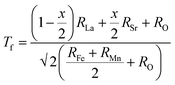 | (1) |
where,
RLa is the ionic radius of La,
RSr is the ionic radius of Sr,
RFe is the ionic radius of Fe,
RMn is the ionic radius of Mn, and
RO is the ionic radius of O. These values are as follows:
RLa3+ = 1.36 Å;
RSr2+ = 1.44 Å;
RMn3+ = (HS: 0.65 Å, LS: 0.58 Å);
RFe3+ = (HS: 0.65 Å, LS: 0.55 Å); and
RO2− = 1.35 Å. The tolerance factor typically lies between 0.75 to 1.02 for a stable perovskite structure. If
Tf = 1, perovskites adopt an ideal cubic structure. In this study, the tolerance factor was obtained in the range of 0.977 to 1.006 (as given in
Table 2), which is close to 1, supporting the cubic symmetry of the samples. The change in
Tf with Sr substitution is attributed to the difference in ionic radii between the La
3+ and Sr
2+ cations, which indicates their good structural stability.
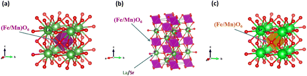 |
| | Fig. 2 (a)–(c) Unit cell of the crystal lattice of La2−xSrxFeMnO6 for x = 0, 0.5 and 2.0, respectively. | |
Table 2 Tolerance factor, crystallite size, micro-strain, density and porosity of the La2−xSrxFeMnO6 (where x = 0.0, 0.1, 0.2, 0.5, 1.0, 1.5, and 2.0) samples
| Concentration (x) |
Tolerance factor (t) |
Crystallite size (nm) |
Micro-strain (×10−3) |
X-ray density (g cm−3) |
Measured density (g cm−3) |
Porosity ∼(%) |
| Cubic |
Rhombohedral |
Cubic |
Rhombohedral |
|
x = 0.0 |
0.978 |
133 |
— |
0.47 |
— |
26.95 |
5.02 |
81.4 |
|
x = 0.1 |
0.979 |
152 |
— |
0.41 |
— |
26.61 |
4.87 |
81.7 |
|
x = 0.2 |
0.980 |
96 |
— |
0.42 |
— |
26.44 |
4.66 |
82.4 |
|
x = 0.5 |
0.984 |
— |
185 |
— |
0.13 |
08.63 |
4.64 |
46.2 |
|
x = 1.0 |
0.992 |
50 |
142 |
0.89 |
0.26 |
16.05 |
4.42 |
72.5 |
|
x = 1.5 |
0.999 |
49 |
354 |
0. 05 |
1. 03 |
13.68 |
3.25 |
76.2 |
|
x = 2.0 |
1.006 |
75 |
— |
0.05 |
— |
22.13 |
4.16 |
81.2 |
The crystallite size (D) and lattice micro strain (ε) were calculated from the XRD data of the synthesized samples. Various methods are available to calculate these parameters such as Williamson–Hall (W–H) analysis, pseudo-Voigt function, and Warren–Averbach analysis, considering the effect of the strain-induced XRD peak broadening, and accurately estimate the crystallite size along with the intrinsic strain. Among them, the W–H method for the analysis is generally used to distinguish the XRD peak broadening induced by crystallite size and microstrain.43 In this model, line broadening induced by crystallite size and micro strain contributes independently to the total integral breadth of the full-width-at-half maximum (FWHM) of a diffraction peak. According to this model, a uniform micro-strain develops in all crystallographic directions. The FWHM of the Bragg peak is the addition of broadening induced by both the crystallite size and the micro strain, which is expressed as follows:
| | βhkl = βcrystallite![[thin space (1/6-em)]](https://www.rsc.org/images/entities/char_2009.gif) size + βmicrostrain size + βmicrostrain | (2) |
The broadening of the diffraction peaks induced by the crystallite size is written as follows:
| |  | (3) |
where
K = 0.94 is a constant for a spherical-shaped particle,
λ is the wavelength of X-ray radiation (0.15406 nm for Cu Kα radiation),
D is the crystallite size, and
θ is the Bragg angle. The broadening of the diffraction peaks induced by the micro-strain is expressed as follows:
| | | βmicrostrain = 4εtanθ | (4) |
Using
eqn (2)–(4), the total broadening of diffraction peak can be expressed as:
| | 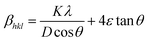 | (5) |
Rearranging
eqn (5), we get
eqn (6), which is known as the uniform deformation model (UDM) equation.
| | 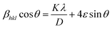 | (6) |
A plot is drawn with (4
sin
θ) along the
X-axis and (
βhklcos
θ) along the
Y-axis using values obtained from each diffraction peak of the XRD pattern. In this case,
βhkl (FWHM in radians) for each diffraction peak was taken after subtracting the instrumental broadening (
βi) from the observed broadening (
β0),
34 which is an important step in the W–H analysis. The value of
β0 for each prominent XRD peak was obtained by peak fitting using the Gaussian function. The best linear fitting of these data points indicates a uniform deformation model. According to the resulting straight line, the crystallite size can be determined from the intercept at the
Y-axis, and the slope of the resulting straight line provides the corresponding intrinsic micro strain. The average crystallite size of the prepared samples was estimated from the W–H method, which was found to be in the range of 49 to 354 nm, as given in
Table 2. The value of intrinsic micro strain for all the synthesized samples is found in the range of 0.03 × 10
−3 to 0.47 × 10
−3, which is also given in
Table 2.
Fig. 3(a)–(d) shows the W–H plot of La
2−xSr
xFeMnO
6 DPs for some selected samples of
x = 0.0, 0.5, 1.0, and 2.0.
 |
| | Fig. 3 Williamson–Hall plot for (a) La2FeMnO6 (x = 0.0), (b) La1.5Sr0.5FeMnO6 (x = 0.5), (c) LaSrFeMnO6 (x = 1.0), and (d) Sr2FeMnO6 (x = 2.0). | |
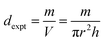
The porosity of the synthesized samples in percentage (P%) was calculated using their X-ray and experimental densities based on the following relation:
| | 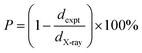 | (7) |
The value of
P (%) for all the synthesized materials was found to be in the range of 46% to 83%, which are listed in
Table 2. The smallest porosity (∼46%) is observed for
x = 0.5, while the highest porosity (∼86%) is observed for the
x = 1.5 sample. The X-ray or theoretical densities (
dX-ray) of all the synthesized samples were calculated using the following relation:
| |  | (8) |
where
Z represents the number of molecules per unit cell (
Z = 2 for body-centered cubic structures and
Z = 4 for rhombohedral structures),
M is the molecular weight of the sample,
NA is Avogadro's number (6.023 × 10
23 particles per mol), and
V is the unit cell volume in cm
3. The experimental (measured) densities (
dexp) of all the synthesized materials were measured using their cylindrical pellets and the following equation:
| |  | (9) |
where
m,
V,
r, and
h represent the mass, volume, radius, and thickness of the pellet, respectively. It is important to note that the X-ray density depends directly on the molecular weight and lattice parameters of the sample, while the experimental density is calculated from the mass and volume of the geometry of materials. The measured densities of all the synthesized materials are lower than their corresponding X-ray densities, primarily due to their porous nature resulting from the solid-state reaction (SSR) synthesis route. Both the theoretical and measured densities of all the synthesized materials are summarized in
Table 2.
3.2 Surface and elemental analysis
The microstructure and surface morphology of the sintered pellets were examined using a field emission scanning electron microscope (FE-SEM). Fig. 4(a)–(c) show the SEM images of the cross-section area of the pellets after Au coating, showing ‘stacked flake-like’ grains. The average grain size was estimated from the grain size distribution histograms obtained from the FESEM micrographs using the ImageJ software. As illustrated in Fig. 4(d)–(f), the estimated average grain sizes for the samples with compositions x = 0.0, 0.2, and 0.5 are ∼4 µm, 1.5 µm, and 0.2 µm, respectively. Generally, ideal cubic perovskites typically exhibit isotropic thermal expansion along each of their three axes because their crystal structure is symmetrical. However, in the case of the La2−xSrxFeMnO6 material, anisotropic thermal expansion is observed during grain formation, as shown in the inset of Fig. 4(a) and (b). This expansion contributes to the development of micro porosity.44 A significant increase is observed in pore size with Sr substitution, reducing the structural density of the synthesized material. We also estimated the porosity of the sintered pellets at RT in the XRD section. The observed trend of porosity in the SEM micrographs with Sr substitution corroborates well with the porosity calculated using the XRD results. The EDAX spectra of the x = 0.0, 0.2, and 1.5 compositions reveal the presence of La, Sr, Mn, Fe, and O elements with their ideal atomic ratios, as shown in Fig. 4(g)–(i). The atomic and weight percentages of the elements present in the x = 0, 0.2, and 1.5 samples are listed in Table 3. The elemental percentages of these elements indicate a slight oxygen deficiency and a minor excess of La, Fe and Mn cations compared to their ideal stoichiometric ratios, indicating the presence of a very small amount of oxygen vacancies in the lattices. These results are corroborated by results obtained from the Rietveld refinement of the XRD data.
 |
| | Fig. 4 (a)–(c) FESEM images, (d)–(f) corresponding grain size distribution histograms, and (g)–(i) EDS spectra of La2−xSrxFeMnO6 for x = 0.0, 0.2, and 1.5, respectively. | |
Table 3 Weight/atomic percentage (%) of the elements present in La2−xSrxFeMnO6 (where x = 0.0, 0.2, and 1.5) material
| Elements |
x = 0.0 |
x = 0.2 |
x = 1.5 |
| Weight (%) |
Atomic (%) |
Weight (%) |
Atomic (%) |
Weight (%) |
Atomic (%) |
| La L |
58.8 |
20.1 |
55.3 |
19.9 |
20.7 |
6.6 |
| Sr L |
0.0 |
0.0 |
3.1 |
1.8 |
28.8 |
14.6 |
| Fe K |
10.0 |
8.5 |
12.0 |
10.7 |
14.4 |
11.5 |
| Mn K |
10.1 |
8.7 |
11.2 |
10.2 |
16.6 |
13.4 |
| O K |
21.1 |
62.6 |
18.4 |
57.4 |
19.5 |
54.0 |
3.3 Raman analysis
Raman spectroscopy is a powerful technique for analyzing the lattice dynamics, vibrational modes, and atomic structure of materials. In the ideal cubic perovskite ABO3, Raman-active modes are absent because all the atoms are occupied at centrosymmetric positions. However, deviation from cubic symmetry, primarily due to tilting of the BO6 octahedra, introduces Raman activity. This tilting can be influenced by the ionic radius of the A-site cation, leading to structural distortions. Specifically, the movement of oxygen atoms within the BO6 octahedra around the B-site atoms gives rise to Raman-active vibrational modes. The vibrational frequency of the Raman modes is influenced by both the bond length and the reduced mass of the vibrating system. As a result, the Raman lines for lighter cations and lower bond length between cations take place at the higher wavenumber side, and vice versa. The Raman spectra of the La2−xSrxFeMnO6 (where x = 0.0, 0.1, 0.2, 0.5, 1.0, 1.5, and 2.0) materials were recorded in the range of 100–3000 cm−1, which are shown in Fig. 5. The recorded Raman spectra matched well with that previously reported in the literature.17,31 Two prominent phonon modes were observed in the range of 485–502 cm−1 and 653–672 cm−1, which are related to the anti-stretching and/or bending vibrations of the (Fe/Mn)O6 octahedra with A1g symmetry and the stretching (“breathing”) vibrations of the (Fe/Mn)O6 octahedra with B1g symmetry, respectively.17,31,34,45 Sr doping changes the position and intensity of the peaks associated with the A1g and B1g Raman modes, which indicates the successful doping of Sr ions. The noticeable change in the Raman shift of both the A1g and B1g modes with Sr concentration is a result of the bond length of the Fe–O and Mn–O bonds. The highest peak intensity of the Raman modes is observed for rhombohedral symmetry (x = 0.5), which indicates minimal distortion in the rhombohedral lattice. Further, the Raman peak intensity of each lattice phase (cubic and rhombohedral) decreases with an increase in the Sr substitution amount, leading to distortion in the lattice of La2FeMnO6 due to the mismatch in the ionic radii of La3+ (1.36 Å) and Sr2+ (1.44 Å) atoms.
 |
| | Fig. 5 Raman spectra of La2−xSrxFeMnO6 (where x = 0.0, 0.1, 0.2, 0.5, 1.0, 1.5, and 2.0). | |
3.4 X-ray photoemission spectroscopy (XPS) analysis
X-ray photoemission spectroscopy (XPS) is a powerful tool for studying the surface elemental composition, chemical and electronic structure of individual elements, empirical formula of doped and undoped samples, and their corresponding binding energy (BE). It is widely recognized for investigating the electronic characteristics of materials. In this technique, samples are irradiated with Al Kα X-rays (hν = 1486.6 eV) and the kinetic energy of the emitted electrons is measured. The emitted photoelectron is the result of the complete transfer of incident energy (hν) to a core-level electron. This can be expressed mathematically as follows:where hν is the energy of the Al Kα X-rays; BE is the energy that binds an electron tightly with the atom/orbital, which is called the binding energy; KE is the kinetic energy of the emitted photo electrons and Φspec is the work function of the spectrometer, which is constant for the instrument used. The photoelectron binding energy is measured with respect to the Fermi level of the sample (not the vacuum level), which is why Φspec is included. The BE of an electron is a material property and is independent of the X-ray source used to eject it, while KE changes for different X-ray sources. This concept is demonstrated by a simple schematic energy level diagram in Fig. 6. Hence, the oxidation states of the elements present in materials have been identified by the BE of an ejected electron, where the BE is determined using eqn (10). The XPS spectra of the x = 0.0, 0.5, and 2.0 samples were recorded to learn about their electronic structure. The XPS database hosted by the National Institute of Standards and Technology (NIST) was used to calibrate the peak positions and doublet separations in all the recorded XPS spectra. The XPS survey scan spectra reveal that La, Mn, Fe, and O elements are present in all the measured samples, while Sr is present in both the x = 0.5 and x = 2.0 samples, as shown in Fig. 7(a). We set the C 1s peak (adsorbed from air on the surface) at 284.8 eV in the survey scan spectrum as the reference energy.
 |
| | Fig. 6 Schematic of the energy level diagram for charge hopping in the XPS technique. | |
 |
| | Fig. 7 (a) XPS survey scan; core-level spectra of (b) La 3d, (c) Sr 3d, (d) Fe 2p, (e) Mn 2p, and (f) O 1s for La2−xSrxFeMnO6 with x = 0.0, 0.5, and 2.0 compositions. | |
Fig. 7(b) displays the core-level XPS spectra of La 3d for the x = 0.0 and 0.5 samples. The spin–orbit split peaks associated with La 3d3/2 and La 3d5/2 appear in a binding energy in the range of 850.3–851.2 eV and 833.7–834 eV, respectively. The separation energy (ΔE) of the La 3d3/2–La 3d5/2 spin–orbit split is obtained in the range of 16.6–17.2 eV. Besides these peaks, other binding energy peaks are also observed in all the measured samples. The La 3d3/2–La 3d5/2 spin–orbit split is attributed to the excitation of an electron coming from the O 2p valence band and transferred into the unoccupied La 4f orbital, which is associated with the other observed peaks (La 3d shake-up state).46 The ΔE value for the La 3d3/2–La 3d5/2 spin–orbit is reported in the range of 16.6–16.9 eV, indicating the La3+ oxidation state.47 Thus, the observed features reveal that the La ion exists in the La3+ oxidation state.
Fig. 7(c) displays the core-level XPS spectra of the Sr 3d for x = 0.5 and 2.0 samples. The spin–orbit split Sr 3d3/2–Sr 3d5/2 peaks are observed in the range of 132.9–134.5 eV and 131.1–132.6 eV for Sr 3d3/2 and Sr 3d5/2, respectively. The doublet separation energy (ΔE) for this splitting is found in the range of 1.7–2.0 eV, indicating the Sr2+ oxidation state.48,49 Another peak is observed in the range of 132.6–134.1 eV, which originates from the Sr–OH, Sr–CO3, Sr–Sr, and Sr–O bonds on the surface area of the materials.49
Fig. 7(d) represents the Fe 2p core-level XPS spectra of the x = 0.0, 0.5, and 2.0 samples. They consist of 4 peaks at x = 0, while 3 peaks are observed in the Sr-doped x = 0.5 and x = 2.0 samples. The peaks positioned in the range of 709.4–710.4 eV and 723.1–724.4 eV are related to Fe 2p3/2 and Fe 2p1/2, respectively, which are associated with the Fe3+ oxidation state.46 In the case of the Fe 2p3/2–Fe 2p1/2 spin–orbit split, the value of ΔE was obtained in the range of 13.7–14.0 eV. For this spin–orbit split, the value of ΔE is reported to be ∼13.7 eV, which is associated with the Fe3+ oxidation state.50 In addition, the other peak observed in the range of 711.9–713.1 eV is ascribed to the Fe4+ oxidation state, which is related to the creation of La vacancies.51 All these observations indicate the presence of mixed Fe3+ and Fe4+ oxidation states. The deconvolution analysis of the Fe 2p core-level XPS spectra shows an increment in the percentage of Fe3+ (52% for x = 0 to 88% for x = 0.5) oxidation state and decrease in Fe4+ (48% for x = 0 to 12% for x = 0.5) with Sr2+ substitution, which was predicted earlier, because the system would essentially attempt to preserve charge neutrality. In addition, a prominent charge transfer satellite peak is observed between the main Fe 2p split peaks at ∼719.4 eV, which appears very weak relative to the main peaks.
Fig. 7(e) shows the XPS spectra of the Mn 2p core-level for the x = 0.0, 0.5, and 2.0 samples. Deconvolution of the Mn 2p core-level XPS spectra revealed three prominent peaks, where the first two are observed in the range of 640.9–641.4 eV and 642.3–643.0 eV for Mn 2p3/2 and the third is observed in the range of 652.7–653.5 eV for Mn 2p1/2. The doublet separation energy (ΔE) for the Mn 2p3/2 (640.9–641.4 eV)–Mn 2p1/2 (652.7–653.5) spin–orbit split is observed in the range of 11.8–12.0 eV, which indicates that the Mn ions exist in the +3 oxidation state (Mn3+).48,52 The other peaks for Mn 2p3/2 are observed in the range of 642.3–643.0 eV, which are attributed to the Mn4+ oxidation state.53 Based on these characteristic, the Mn cations are present in the mixed valence states of +3 and +4 (i.e. Mn3+ and Mn4+). Deconvolution of the Mn 2p core-level XPS spectra indicates a considerable increment in the concentration of the Mn3+ (73% for x = 0 to 86% for x = 0.5) oxidation state due to Sr2+ doping.
The XPS O 1s core-level spectra of the x = 0.0, 0.5, and 2.0 samples are displayed in Fig. 7(f). Two distinct peaks can be observed in the range of 527.9–529.6 eV and 530.1–530.9 eV; (i) the peak centered at ∼529 eV is attributed to lattice oxygen (OL), which is associated with the La–O and Fe/Mn–O bonds and (ii) the peak centered at ∼531 eV is attributed to surface-adsorbed oxygen from the air, oxygen vacancies (OV) and oxygen species (OH) (i.e., O22−, O2−, or O−), respectively.48
3.5 Fourier transform infrared (FTIR) analysis
FTIR spectroscopy provides important information about the bonding between the metal and oxygen ions within the structural lattice. In ABO3 perovskites, the fundamental IR absorption bands associated with the vibrational frequencies of metal–oxygen bonds typically appear in the range of 400–650 cm−1.54Fig. 8 shows the FTIR spectra of the La2−xSrxFeMnO6 (where x = 0.0, 0.2, 0.5, 1.0, 1.5, and 2.0) compounds. Two prominent bands can be observed in the FT-IR spectra of all the samples; the first is observed at ∼440 cm−1 and the second is at ∼640 cm−1, which are associated with the Fe–O and Mn–O bond stretching vibrations of the FeO6 and MnO6 octahedra, respectively.55 Further, it was observed that Sr substitution does not introduce any new bands or eliminate existing ones across the entire FTIR spectrum. The position of bands associated with the Fe–O and Mn–O stretching vibrations varies with the Sr concentration. The vibrational band positions of the Fe–O and Mn–O bonds exhibit a noticeable shift toward the higher wavenumber side in the samples with compositions x = 0.5, 1.0, and 2.0, whereas a shift toward the lower wavenumber side is observed for the samples with x = 0.2 and 1.5. Generally, the vibrational frequency of the bond stretching vibrations is determined by the force constant and the reduced mass of the bonded atoms. According to classical mechanics and Hooke's law, the vibrational frequency (![[small upsilon, Greek, macron]](https://www.rsc.org/images/entities/i_char_e0d5.gif) ) in wavenumber (cm−1) can be expressed as follows:33,54
) in wavenumber (cm−1) can be expressed as follows:33,54| |  | (11) |
where , c, k, and μ are the wavenumber (cm−1), speed of light, force constant of the bond (related to bond strength), respectively, and μ is the reduced mass of the bonded atoms. According to Badger's rule, the force constant (k) can be calculated using the following relation:33,54| |  | (12) |
where r is the bond length between metal–oxygen (M–O) bonds obtained by the crystallographic data in the XRD section (see Table 1). According to eqn (11) and (12), it can be inferred that the bond length (r) is inversely proportional to both the force constant (k) and the vibrational frequency (). The M–O bond length (r) is higher for the x = 0.1, 0.2, and 1.5 samples and lower for x = 0.5, 1.0 and 2.0 compared to the undoped sample (x = 0.0), as given in Table 1. Then the force constant (k) and vibrational frequencies () of the Fe–O and Mn–O bonds will be lower for x = 0.2 and 1.5, and higher for the x = 0.5, 1.0 and 2.0 samples compared to the undoped La2FeMnO6 (x = 0.0) sample.
 |
| | Fig. 8 FTIR spectra of the La2−xSrxFeMnO6 (where x = 0.0, 0.2, 0.5, 1.0, 1.5, and 2.0) compounds. | |
3.6 DC resistivity analysis
The change in the DC resistivity of the La2−xSrxFeMnO6 (where x = 0.0, 0.2, 0.5, 1.5, and 2.0) compounds with temperature (T) is plotted in Fig. 9(a). The semiconducting nature of the synthesized samples can be observed in the temperature range of 150–300 K. In the narrow high temperature region above 250 K, the resistivity data fitted well with the Arrhenius model, as shown in Fig. 9(b). The Arrhenius model is described by the following equation:| | 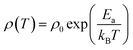 | (13) |
where ρ0 is a constant contribution caused by defects, Ea is the energy required for conduction and is called the activation energy, kB is the Boltzmann constant, and T is temperature. The fitting of the resistivity data at high temperatures indicates that the conduction is primarily governed by long-range percolative transport, where charge carriers move by hopping over energy barriers due to high thermal energy. In this regime, the carriers are effectively excited beyond the mobility edge. The corresponding activation energies are listed in Table 4(a). The resistivity behavior below a temperature of 250 K deviates from that observed at higher temperatures. In this region (low-temperature region), the experimental DC resistivity data are fitted well by the variable range hopping (VRH) model, as shown in Fig. 9(c). The resistivity analysis based on this model indicates that the charge transport occurs via phonon-assisted quantum tunneling of the charge carriers to energetically favorable localized states under conditions where thermal energy is significantly lower than the disorder-induced energy (for example, originating from crystal imperfections), which are not necessarily the nearest neighbors. This transport mechanism is commonly referred to as polaron hopping, which predominantly takes place in the vicinity of the Fermi level. According to this model, the temperature dependence of resistivity (ρ) is described by the following expression:| | 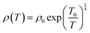 | (14) |
where ρ0 is the pre-exponential factor and T0 is the characteristic temperature, which are given as follows:
| ρ0 = [(3e2νph)/{8παkBT/N(EF)}1/2]−1 |
and,
where νph (∼1013 s−1), N(EF), α denote the phonon frequency at the Debye temperature, localized electron states at the Fermi level, and inverse localization length, respectively. At low temperatures, the resistivity behavior of La2FeMnO6 is well described by the variable range hopping of small polaron (VRH-SP) conduction in our earlier published paper.17 The activation energy (Eρ) for the VRH conduction mechanism can be estimated using the following relation:The estimated activation energy values are given in Table 4(a). The magnitude and trend of the activation energies derived from the linear fitting of resistivity align closely with that reported for other systems exhibiting polaron hopping conduction, including compounds such as FeTiTaO6,56 Ca1−xDyxBaFe4O7,57 and various manganites.58–60 A quantitative comparison of the activation energy with some earlier reported systems is given in Table 4(b). The hopping range (R) can be approximated utilizing the following expression:| |  | (16) |
where ξ denotes the decay length of the polaronic wave function. In oxide materials, electron injection typically arises from the formation of random oxygen vacancies, which subsequently undergo ionization to contribute free electrons.61,62 Furthermore, the material under investigation exhibits an irregular arrangement of Fe3+/4+ and Mn3+/4+ ions, potentially indicating improper charge ordering. At low temperatures, electrons are expected to remain localized within the potential wells formed by the Fe and Mn cations. The average distance of Fe–Mn, Fe–Fe, and Mn–Mn separation can serve as a calculation of the decay length ξ in the corresponding equation. The averaged values are used to estimate ξ, which in turn allows the calculation of the hopping range R, as given in Table 4(a). The resulting R values suggest that the polaron transport occurs via a short-range variable-range hopping (VRH) mechanism, consistent with findings reported in previous studies.57,63 At this stage, it is important to acknowledge that the DC resistivity measurement reflects contributions from both grain boundaries and the intrinsic properties of individual grains. However, in bulk samples such as those studied here, the resulting parameters and their functional behavior remain largely consistent with those expected from an ideal sample. The intrinsic grain response associated with DC resistivity can be extracted from AC measurements.
 |
| | Fig. 9 (a) Temperature dependence of DC resistivity, (b) linear fitting of lnρ versus 1000/T (Arrhenius model), and (c) linear fitting of lnρ versus T−1/4 (VRH model) for the La2−xSrxFeMnO6 samples. | |
Table 4 (a) Parameters derived from the DC resistivity analysis based on the Arrhenius and variable range hopping (VRH) models. (b) Comparison of the activation energy (Eρ) derived from the VRH model with some earlier reported manganites
| (a) |
Arrhenius model |
VRH model |
| Sr concentration (x) |
E
a (meV) |
T range (K) |
T
0
1/4 (K1/4) |
E
ρ
(meV) |
ξ (Å) |
R (Å) |
T range (K) |
|
x = 0.0 |
176 |
264–300 |
— |
— |
|
— |
— |
|
x = 0.2 |
060 |
271–300 |
133.40(±0.1) |
124–174 |
3.9096 |
40–35 |
151–237 |
|
x = 0.5 |
035 |
266–300 |
116.77(±0.1) |
108–157 |
3.8908 |
35–30 |
150–248 |
|
x = 1.5 |
105 |
245–300 |
166.98(±0.1) |
155–223 |
5.5176 |
70–62 |
152–245 |
|
x = 2.0 |
120 |
237–300 |
151.26(±0.3) |
141–197 |
3.8550 |
44–39 |
152–237 |
| (b) |
| Compounds |
E
ρ
(meV) |
T range (K) |
Ref. |
| FeTiTaO6 |
140–260 |
123–293 K |
56
|
| Ca1−xDyxBaFe4O7 |
|
|
57
|
|
x = 0.00 |
128–175 |
145–220 |
|
|
x = 0.01 |
183–228 |
159–213 |
|
|
x = 0.03 |
198–259 |
140–200 |
|
|
x = 0.05 |
90–125 |
127–197 |
|
| Pr0.6Sr0.4Mn0.6Ti0.4O3±δ |
113–303 |
130–275 |
58
|
| La0.9Sr0.1MnO3 |
71–105 |
170–280 |
59
|
| La0.8Na0.2MnO3 |
83–142 |
220–460 |
60
|
| Ni0.5Zn0.5Fe2O4 |
143–223 |
130–235 |
63 [Fig. 3] |
| La2−xSrxFeMnO6 |
|
|
This paper |
|
x = 0.2 |
124–174 |
151–237 |
|
|
x = 0.5 |
108–157 |
150–248 |
|
|
x = 1.5 |
155–223 |
152–245 |
|
|
x = 2.0 |
141–197 |
152–237 |
|
3.7 Dielectric analysis
Fig. 10(a) shows the frequency-dependent variation in the real dielectric constant (ε′) in the frequency range of 700 Hz to 2 MHz for the La2−xSrxFeMnO6 (where x = 0.0, 0.1, 0.2, 0.5, 1.0, 1.5, and 2.0) compounds at RT. The real part of the dielectric constant (ε′) exhibits higher values at lower frequencies, and it decreases sharply with an increase in frequency up to a certain value; beyond this, it reaches a steady state at higher frequencies. The higher value of ε′ at low frequencies is primarily attributed to interfacial space charge polarization at the interfaces between the conducting grains and insulating grain boundaries.64,65 At higher frequencies, the reduction in ε′ is due to the inability of charge carriers to align with the rapidly alternating electric field,66 causing electronic and/or ionic polarization to become dominant.34 Further, for the x = 0.1, 0.2 and 1.0 samples, the value of ε′ becomes negative via crossing zero at a specific frequency point. Other cermets have been reported to exhibit similar phenomena at higher frequency.67–69 Generally, negative permittivity is caused by the plasma oscillations of free or delocalized electrons and dielectric resonance phenomenon within a material.40,68–70 This phenomenon is commonly observed in metals, semiconductors and metamaterials, or inductive effects from percolating conductive networks. Under the influence of an external electric field, both free electrons and localized charges contribute to the dielectric response. In contrast, localized charges tend to align with the applied electric field through polarization and free electrons undergo collective oscillations (known as plasma oscillations) along the direction of the field.40,68 The dielectric resonance of a dielectric usually occurs under an applied electric field when the frequency of the applied electric field is the same as the natural vibrational frequency of various micro entities in the samples, which may be atoms, valence electrons, and an inner-electrons. This resonance usually occurs at higher frequencies. With an increase in the applied frequency, the permittivity of the material changes from positive to negative at a particular frequency. At high frequencies, the speed of polarization switching lags far behind the applied electric field. As a result, the electric field increases toward the positive direction, leading to polarization in the negative direction due to the phase angle difference between the polarization vector and applied electric field.68,69 In this case, negative permittivity occurs in a narrow frequency region just above the resonance frequency (ω0), before becoming positive again at higher frequencies. This is an obvious phenomenon of dielectric resonance, which can be explained by the Lorentz model,67,68 as follows:| |  | (17) |
where ΓL is the damping factor of the Lorentz resonance, ω0 is the Lorentz resonance frequency, and K is the polarizability under a DC electric field. When the frequency (ω) under the applied electric field is just above the resonance frequency (ω0) of the material, negative permittivity occurs.
 |
| | Fig. 10 Frequency dependence of (a) dielectric constant, (b) dielectric loss tangent (tanδ), and (c) AC conductivity of the La2−xSrxFeMnO6 samples at room temperature. | |
Fig. 10(b) shows the frequency-dependent variation in dielectric loss tangent (tanδ) for the La2−xSrxFeMnO6 samples in the frequency range of 700 Hz to 2 MHz. This behavior is primarily attributed to interfacial space charge polarization effects.20 Additionally, it is observed that the loss tangent value increases for Sr substitution. In contrast, for the x = 0.1 and 1.0 samples, the loss tangent value decreases compared to the undoped sample. The variation in ε′ and tanδ with Sr concentration can be governed by several defects such as more modest grain size, distortion/stress, strain, and oxygen vacancy created by Sr substitution in the La2−xSrxFeMnO6 semiconducting material.20,34 All these defects can lead to variations in the conductivity of the material, as further evidenced by AC conductivity measurements. All the synthesized samples exhibit frequency-dependent dispersion and relaxation in their dielectric constants. Among them, the sample with the composition x = 0.1 demonstrates a comparatively higher dielectric constant across the measured frequency range. Particularly, the dielectric loss tangent (tanδ) for the x = 0.1 sample remains lower than that of the other compositions in the entire frequency range, except for x = 1.0. The best combination of high dielectric constant and low dielectric loss for the x = 1.0 sample suggests that it possesses superior energy storage capability compared to the other synthesized samples. The detailed frequency-dependent dielectric parameters are summarized in Table 5(a). This finding demonstrates that the dielectric constant and dielectric loss tangent of La2FeMnO6 are greatly affected by Sr substitution. In our previous study,34 we have reported the highest dielectric constant of ∼1.52 × 10⁴ at 4 kHz near room temperature (RT) for the La2−xCaxFeMnO6 system with the composition x = 0.1 (viz, La1.9Ca0.1FeMnO6), and presented a brief comparison with some earlier reported high dielectric materials. In this study, the dielectric constant was determined to be ∼4.8 × 10⁴ at 4 kHz near RT for the La2−xSrxFeMnO6 system with the x = 0.1 composition, which can make it more interesting for application in advanced technologies as a high dielectric material compared to earlier reported dielectric materials (Table 5 in ref. 34). Colossal/giant dielectric (ε′ ≥ 103) materials are not widely used as commercial dielectric materials in industrial applications due to their high energy loss but they are an active area of research for potential future applications. However, the highest obtained dielectric constant value for the x = 0.1 (viz, La1.9Sr0.1FeMnO6) sample is compared with some existing commercial as well as non-commercial dielectric materials, as listed in Table 5(b).
Table 5 (a) Real dielectric constant (ε′), tangent dielectric loss (tanδ), and AC conductivity (σac) for the La2−xSrxFeMnO6 (where x = 0.0, 0.1, 0.2, 0.5, 1.5, and 2.0) compounds near room temperature at 757 Hz and 1 MHz. (b) Quantitative comparison of the dielectric constant (ε′) of the La1.9Sr0.1FeMnO6 (x = 0.1) sample with those of some earlier reported dielectric materials at room temperature (RT)
| (a) |
Frequency at 757 Hz |
Frequency at 1 MHz |
| Concentration (x) |
ε′ (×104) |
Tanδ (×102) |
σ
ac × 10−4 (S m−1) |
ε′ (×104) |
Tanδ (×102) |
σ
ac × 10−4 (S m−1) |
| 0.0 |
0.74 |
2.85 |
3.11 |
0.17 |
0.017 |
1072 |
| 0.1 |
5.21 |
2.91 |
21.9 |
−0.94 |
0.014 |
−5700 |
| 0.2 |
1.80 |
6.50 |
7.61 |
−0.33 |
0.215 |
−2455 |
| 0.5 |
0.41 |
18.09 |
1.71 |
0.23 |
0.026 |
1567 |
| 1.0 |
1.82 |
2.01 |
7.67 |
0.30 |
0.034 |
1407 |
| 1.5 |
0.10 |
6.03 |
0.43 |
0.07 |
0.006 |
281 |
| 2.0 |
0.13 |
8.26 |
0.54 |
0.07 |
0.008 |
350 |
| (b) |
| S. no. |
Compounds |
Dielectric constant (ε′) at RT |
Dielectric loss (tanδ) |
Synthesis method |
Ref. |
| 1 |
(1 − x)K0.5Na0.5NbO3−xBi (Li0.5Ta0.5)O3 (x = 0, 0.05, 0.10, 0.15, 0.20) |
∼850–1200 @ 1 kHz |
0.01–0.9 |
Solid-state reaction |
71
|
| 2 |
Sr1−xCaxTiO3 (x = 0, 0.02, 0.04 and 0.08) |
∼275–335 @ 1 kHz |
2 × 10⁻³ |
Solid state reaction |
72
|
| 3 |
(Ba0.7Sr0.3)1−xNdxTi1−yMnyO3 (x = 0; y = 0) − (x = 0.005; y = 0) |
∼(1.9–2.0) × 103 @ 1 kHz |
(2.18–2.66) × 10−2 |
Solid-state reaction |
73
|
| 4 |
Al2O3 |
∼2.8 × 10⁴ @ 1 kHz |
0.12 |
Colloidal processing |
74
|
| 5 |
Ti1−xFexO2 (x = 0, 0.02, and 0.05) |
∼105, 84, and 76 @ 1 kHz |
— |
Sol–gel |
75
|
| 6 |
La0.67LixTi1−xAlxO3 (where x = 0.05, 0.2, 0.3) |
∼104–105 @ 1 kHz |
1.4–1.8 |
Sol–gel Pechini method |
76
|
| 7 |
Steatite |
6.0 @ 1 Hz |
(1.4–22) × 10−3 |
Commercial |
77
|
|
|
5.7–6.5 @ 1 MHz |
(1–6) × 10−3 |
|
| 8 |
Al2O3 |
8.0–9.0 @ 1 Hz |
(3.1–11) × 10−4 |
Commercial |
78
|
|
|
7.8–11 @ 1 MHz |
(4.9–13) × 10−4 |
|
| 9 |
ZrO2 |
28 |
— |
Commercial |
79
|
| 10 |
ZrSiO4 |
8.8 |
— |
Commercial |
80
|
| 11 |
Porcelain |
5–10 @ 1 Hz |
(4.3–28) × 10−3 |
Commercial |
81
|
|
|
6.5 @ 1 MHz |
(4.3–130) × 10−4 |
|
| 12 |
BaTiO3 |
1.2 × 10³ @ 1 kHz |
3.78 × 10⁻³ |
Bell Telephone Laboratories |
82
|
| 13 |
LaBaFeTiO6 |
∼400 @ 10 kHz |
∼1.0 |
Solid-state reaction |
83
|
| EuBaFeTiO6 |
∼75 @ 10 kHz |
∼0.5 |
|
| 14 |
La2FeReO6+δ |
∼300 @ 1 kHz |
∼2.5 |
Solid-state reaction |
84
|
| 15 |
CaBiFeMnO6 |
∼4 × 10⁴ @ 100 Hz |
∼9.01 |
Solid-state reaction |
22
|
| 16 |
Co0.65Zn0.35Fe2O4 |
∼7 × 10³ @ 1 kHz |
∼1 |
Solid-state reaction |
19
|
| 17 |
Co1−xNixFe2O4 (x = 0.0, 0.25, 0.5, 0.75, 1.0) |
∼100–200 @ 1 kHz |
∼2 |
Combustion |
20
|
| 18 |
La1.9Ca0.1FeMnO6 |
∼1.4 × 10⁴ @ 1 kHz |
∼122 |
Solid-state reaction |
34
|
| 19 |
Nd2−xSrxNiMnO6 (x = 0.0, 0.1, 0.3) |
∼(4.5, 7.5, 8.2) × 103 @ 1 kHz |
∼120, 30, 158 |
Solid-state reaction |
39
|
| 20 |
La2Co1−xNixMnO6 (x = 0, 0.1, 0.5) |
∼(4.6, 5.8, 5.8) × 103 @ 1 kHz |
∼10, 32, 85 |
Sol–gel |
85
|
| 21 |
Nd2CoIrO6 |
∼5800 @ 1 kHz |
— |
Solid-state reaction |
86
|
| 22 |
La1.9Sr0.1FeMnO6 |
∼5.1 × 10⁴ @ 1 kHz |
∼193 |
Solid-state reaction |
This work |
|
|
−0.94 × 10⁴ @ 1 MHz |
∼1.4 |
|
The AC conductivity (σac) of the La2−xSrxFeMnO6 material was determined using the following expression:
| | | σac = 2πfε′ε0tanδ | (18) |
where
f denotes the applied frequency,
ε0 is the permittivity of free space,
ε′ refers to the real component of the dielectric constant, and tan
δ indicates the dielectric loss factor. The change in AC conductivity with Sr substitution [
Fig. 10(c)] may be attributed to the development of modest grain and enhanced grain boundary effects related to higher grain boundary density and multiple polarization phenomena.
87 The AC conductivity is also influenced by the presence of oxygen vacancies within the samples. Further, an increase in conductivity is observed with an increase in frequency up to a certain value (threshold), which is attributed to the hopping conduction mechanism in the materials. Beyond this frequency,
σac starts to decrease and becomes negative at a MHz frequency, which can be explained by the following expression:
88where
n0 is the number density of electrons,
e is the charge of electrons,
Me denotes the mobility of electrons,
Mi denotes the mobility of ions, and
E is the strength of the applied electric field. Given that electrons are significantly lighter than ions, the mobility of electrons is higher than that of ions, which is more significant in the higher frequency regime. According to
eqn (19), above the plasma resonance frequency (
ω0), the conductivity (
σac) starts to decrease and after a certain value (above plasma resonance frequency), it becomes negative. This decrement in
σac at higher frequencies can be attributed to the skin effect,
40 a phenomenon wherein an alternating current tends to flow predominantly along the surface of a conductor at elevated frequencies. As the frequency increases, this effect leads to an increase in effective resistance, thereby diminishing the overall conductivity. This phenomenon occurs due to the self-induced magnetic field generated by the alternating current, which causes the electrons to become concentrated near the surface of the conductor. As a result, at higher frequencies, the current is confined to a thinner surface layer, effectively reducing the cross-sectional area available for conduction. This leads to an increase in resistance and a corresponding decrease in conductivity. The depth to which the current penetrates the surface is known as the “skin depth.” This parameter is inversely proportional to the square root of both the frequency and conductivity of the material.
Fig. 11(a)–(c) display the variation in the real part of impedance (Z′) of all the synthesized samples with applied frequency in the range of 700 Hz to 2 MHz. The value of Z′ remains constant up to a threshold frequency, after which it starts to decrease with an increase in frequency and tends to merge at higher frequencies. This behavior can be explained by the loss of space charge polarization and decreased in the grain boundary effects in the material.89 This pattern suggests an increment in the electrical conduction of the materials and it corroborates the earlier obtained AC conductivity results. Fig. 11(d)–(f) display the variation in imaginary part of impedance as a function of frequency (100 Hz to 2 MHz). A single relaxation peak can be observed for all the samples, confirming the existence of relaxation phenomena. The frequency f at which Z″ attains its peak is known as the relaxation frequency (fr). The relaxation time τ can be calculated using the relation τ = 1/2πfr.34 A single relaxation peak clearly indicates the contributions of the grain boundary effect. In all the synthesized bulk samples, the electrical response of the grain boundary can be considered an electrical circuit consisting of a parallel combination of resistance, Rgb, and capacitance, Cgb. The resistivity associated with the grain boundary (ρgb) can be estimated using the relaxation peak intensity. The peak intensity is equal to half of the grain boundary resistivity (ρgb/2).86 The grain boundary capacitance (Cgb) can be estimated using the relaxation peak frequency (frgb) based on the relation Cgb = 1/(2πfrgbρgb). The corresponding relaxation time (τgb) can be calculated using the expressions τgb = 1/2πfrgb = ρgbCgb. The calculated values are given in Table 6.
 |
| | Fig. 11 Frequency dependence of the real part of impedance (Z′) (a)–(c), imaginary part of impedance (Z″) (d)–(f), and Nyquist plots (Z″ vs. Z′) (g)–(i) for the La2−xSrxFeMnO6 samples (where, x = 0.0, 0.1, 0.2, 0.5, 1.5, and 2.0) at RT. | |
Table 6 Parameters of La2−xSrxFeMnO6 (where x = 0.0, 0.1, 0.2, 0.5, 1.5, and 2.0) obtained from impedance analysis
| Sr concentration (x) |
f
rgb (Hz) |
ρ
gb (Ω cm) |
C
gb (pF cm−1) |
τ
gb (µs) |
| 0.0 |
373255 |
356 |
1179 |
0.42 |
| 0.1 |
30637 |
62 |
83871 |
5.20 |
| 0.2 |
206714 |
38 |
20263 |
0.77 |
| 0.5 |
1005337 |
95 |
1684 |
0.16 |
| 1.5 |
803433 |
1903 |
105 |
0.20 |
| 2.0 |
906764 |
1342 |
126 |
0.17 |
Fig. 11(g)–(i) display a depressed single semicircular arc (impedance Nyquist plot) with its center positioned below the real axis for all the synthesized samples. The semicircular arcs in the Nyquist plot indicate that the conductivity arises from contributions by either the grains or the grain boundaries. The presence of a single semicircle highlights the significant influence of the grain boundary effect. The depressed semicircular arcs indicate the non-Debye type relaxation in all the measured samples.
3.8 Magnetic analysis
The field-dependent magnetic properties (M–H loop) of the La2−xSrxFeMnO6 materials (where x = 0.0, 0.1, 0.2, 0.5, 1.0, 1.5, and 2.0) were recorded in the range of −20 kOe to +20 kOe at RT. The diversity in magnetic behavior of all the synthesized materials is displayed in Fig. 12. The observed M–H curve is not linear, while it shows a small hysteresis loop at room temperature, which denotes that the antiferromagnetic (AFM) nature no longer exists in the La2−xSrxFeMnO6 (x = 0.0, 0.1, 0.2, 0.5, 1.0 and 1.5) compounds. They started to show weak ferromagnetic (FM) behavior at a low magnetic field strength. In contrast, the sample with the x = 2.0 composition exhibits linear field-dependent magnetization, which is characteristic of paramagnetic (PM) materials. In all the samples, the magnetization increases with an increase in the strength of the applied magnetic field but does not reach saturation, which is the signature of complex magnetic behavior of AFM and FM/ferrimagnetic (FIM).17 The XPS analysis reveals that the Fe and Mn cations exhibit +3 and +4 mixed valence states in all the synthesized materials. Therefore, there are several possible magnetic interactions (FM, FIM and AFM) between the Fe and Mn cations with an oxygen mediator.34 The origin of the non-linear behavior of the M–H loop with weak ferromagnetism was explained well in our earlier published papers.17,34 The corresponding values of maximum magnetization (Mm), coercive field (Hc), remnant magnetization (Mr), and remanence ratio (Mr/Mm) for all the prepared samples were obtained from their hysteresis loop, which are listed in Table 7. The magnetic moment of all the synthesized samples was estimated from their corresponding magnetization data using the following relation:33| | 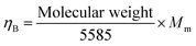 | (20) |
where ηB represents the magnetic moment and Mm denotes the maximum magnetization. The estimated value of magnetic moment is listed in Table 7.
 |
| | Fig. 12 Magnetic hysteresis (M vs. H) loop for the La2−xSrxFeMnO6 (where x = 0, 0.1, 0.2, 0.5, 1.0, 1.5, and 2.0) materials at room temperature. | |
Table 7 Maximum magnetization (Mm), coercive field (Hc), remnant magnetization (Mr), remanence ratio (Mr/Mm), and magnetic moment (ηB) values for La2−xSrxFeMnO6 (where x = 0.0, 0.1, 0.2, 0.5, 1.0, 1.5, and 2.0) at room temperature
| Concentration (x) |
M
m (emu g−1) |
M
r (emu g−1) |
H
c (Oe) |
M
r/Mm |
η
B (BM) |
|
x = 0.0 |
0.62 |
0.01 |
035 |
0.016 |
0.053 |
|
x = 0.1 |
1.67 |
0.10 |
045 |
0.059 |
0.143 |
|
x = 0.2 |
1.50 |
0.08 |
042 |
0.053 |
0.127 |
|
x = 0.5 |
1.62 |
0.03 |
018 |
0.018 |
0.133 |
|
x = 1.0 |
1.65 |
0.25 |
775 |
0.151 |
0.128 |
|
x = 1.5 |
0.96 |
0.04 |
040 |
0.001 |
0.070 |
|
x = 2.0 |
0.41 |
0.00 |
000 |
0.000 |
0.028 |
3.9
I–V characteristics
The current–voltage (I–V) measurement is an important technique for evaluating the performance of electronic devices. It provides essential insight into their functionality. Noticing the importance of this measurement, we recorded the I–V curves of the La2−xSrxFeMnO6 materials at RT. All the synthesized materials exhibit a colossal/giant dielectric constant, as discussed in the previous section. Therefore, it is essential to examine their I–V characteristics for emerging potential applications in electronic devices. Fig. 13(a) shows the variation in current with applied electric field at RT for all the synthesized samples. Here, it can be observed that the conduction current exhibits a nonlinear increase with the applied electric field strength, indicating the semiconducting diode-type nature of all the samples. Hence, they can be used as a rectifier in appropriate electronic devices as a diode. Fig. 13(b) illustrates the relationship between the leakage current density (J) and the applied electric field (E) at RT for all the synthesized compounds. As the electric field increases, the leakage current density also increases. The increase in leakage current density could be attributed to some factors such as the influence of the potential barrier, structural distortions or defects, and the presence of polarized charges under an applied external field.90,91 The trend of change in leakage current density with an increase in applied electric field strength is similar to some earlier reports.17,22,34,90,92–94 All the synthesized materials might be suitable for application in electronic devices because of their low leakage current density (∼10−1–10−7 A cm−2) observed in the electric field range of −15 to +15 V cm−2. It has also been observed that the leakage current density primarily increases for x = 0.1, and then it starts to decrease with an increase in Sr concentration, giving the lowest leakage current density (∼10−7 A cm−2) for x = 2.0. Thus, it becomes more promising for application in electronic devices than the others. A quantitative comparison of the leakage current density values with some earlier reported compounds is given in Table 8.
 |
| | Fig. 13 Electric field-dependent current (a) and leakage current density (J) (b); linear fitting of log(J) vs. log(E) curves (c) for the La2−xSrxFeMnO6 samples at RT and inset of (c) shows two different slopes in two different regions for x = 0.2 sample. | |
Table 8 Lowest leakage current density of some compounds at room temperature
| Compounds |
Lowest J (A cm−2)@RT |
Ref. |
| (1 − x)Bi1+yFeO3−xBaTiO3 |
|
92
|
| 0.25 ≤ x ≤ 0.40; y = 0.00 |
∼10−7–10−8 |
|
| −0.02 ≤ y ≤ 0.04; x = 0.30 |
∼10−7–10−9 |
|
| (1 − x)Bi0.48La0.02Na0.48Li0.02Ti0.98Zr0.02O3−xNa0.73Bi0.09NbO3 (x = 0–0.14) |
∼10−4–10−5 |
93
|
| La2FeMnO6 |
∼10−4 |
17
|
| (K0.44,Na0.52,Li0.04) (Nb0.84,Ta0.1,Sb0.06O3) KNN-LT-LS |
∼10−8 |
90
|
| CaBiFeMnO6 |
∼10−7 |
22
|
| Nd2NiTiO6 |
∼10−7 |
94
|
| La2−xCaxFeMnO6 (x = 0.0, 0.1, 0.2, and 0.5) |
∼10−4–10−5 |
34
|
| La2−xSrxFeMnO6 (x = 0.0, 0.1, 0.2, 0.5, 1.0, 1.5, and 2.0) |
∼10−4–10−7 |
This work |
The substitution of Sr at the La site leads to stress and structural distortion because of the difference in their ionic sizes (as discussed earlier in the XRD section), resulting in the creation of Schottky defects. Additionally, the presence of mixed valence states of Mn and Fe (i.e., Mn3+, Mn4+, Fe3+, and Fe4+) contributes to the formation of oxygen vacancies to preserve charge neutrality, which is confirmed by the XPS analysis. The applied external electric field can activate these multiple valence states, generating free charge carriers, which contribute to the resulting leakage current. There are several potential mechanisms that can explain the limitations of the leakage current in insulating and/or semiconducting materials. These mechanisms are generally categorized into two groups, as follows: (I) interface-limited conduction mechanisms and (II) bulk limited conduction mechanisms. A linear increment in leakage current density with the applied electric field indicates Ohmic conduction behavior. To confirm the conduction mechanism in the La2−xSrxFeMnO6 compound, its leakage current density (J) was plotted against the applied electric field (E) on a logarithmic scale [log(J) vs. log(E)], as illustrated in Fig. 13(c). All these plots exhibit a good linear fit with different slopes. These slopes are close to 1 (S ≈ 1), indicating linear Ohmic conduction in all the samples. In the case of x = 0.2, the linear log(J) vs. log(E) plot was fitted with two distinct slopes, as shown in the inset of Fig. 13(c). The slope (S) is close to 1 in the lower electric field region. Alternatively, in the higher electric field region, the slope is approximately 1.75, indicating space-charge-limited conduction (SCLC).95 Both Ohmic and SCLC conduction are associated with the bulk limited conduction mechanism. The leakage current density associated with Ohmic conduction can be expressed by the following equation:
where Ne represents the density of thermally activated electrons,
µ is the mobility of charge carriers, and
q is the charge of an electron. Further, in the higher electric field region, space-charge-limited conduction (SCLC) occurs due to the accumulation of space charge near the electrodes. The accumulation of space charge occurs when charge carriers are injected from the electrode into the material at a rate exceeding their transport. The current density for the SCLC mechanism can be expressed as follows:
| | 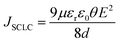 | (22) |
where
µ represents the carrier mobility,
d represents the thickness of the pellet, and
θ is the fraction of injected charge carriers (
θ = 1 in trap-free limit). Hence, the change in slope from 1.03 to 1.75 (for
x = 0.2) indicates a transition in conduction mechanism from Ohmic to SCLC.
4. Conclusion
Polycrystalline La2−xSrxFeMnO6 (where x = 0.0, 0.1, 0.2, 0.5, 1.0, 1.5, and 2.0) samples were successfully prepared via the solid-state reaction method. The Rietveld refinement of their XRD data shows the re-entrant structural phase transition (cubic–rhombohedral–cubic) of the disordered La2−xSrxFeMnO6 materials with Sr-doping. The SEM study shows anisotropic their thermal expansion during grain formation, which leads to the development of micro porosity. Two prominent phonon modes (A1g and B1g) are observed in the Raman spectra of all the synthesized samples, which are associated with the anti-stretching and/or bending and the stretching (“breathing”) vibrations of (Fe/Mn)O6 octahedra, respectively. The XPS study reveals the presence of mixed valence states of Mn and Fe (i.e., Mn3+, Fe3+, Mn4+, and Fe4+) ions in all samples, which contribute to the formation of oxygen vacancies. The semiconducting nature of all the synthesized samples was determined by their temperature-dependent DC resistivity. The charge conduction in all the synthesized samples has been explained by the long-range electron hoping conduction mechanism in the high temperature region and short-range polaron hopping conduction mechanism in the low-temperature region. The dispersion behavior of the dielectric constant with frequency at RT is the contribution of Maxwell–Wagner interfacial polarization. The highest dielectric constant (ε′ ∼ 5.21 × 10⁴) was observed for 5% Sr doping at 700 Hz near RT. The Nyquist complex impedance plot indicates non-Debye-type relaxation in all samples. All the synthesized samples exhibit weak ferromagnetism, in contrast to x = 2.0, which is paramagnet in nature. The highest ferromagnetic strength (Hc = 775 Oe) was observed for 50 Sr doping (i.e., x = 1.0). The sample with the composition x = 2.0 exhibits the lowest leakage current density (∼10−7 A cm−2), which makes it the most promising for electronic device applications.
Author contributions
Baniya R. Meena: conceptualization, methodology, investigation, data curation, software, visualization, validation, results interpretation, formal analysis, writing – original draft, writing – review and editing. Anup K. Ghosh: conceptualization, methodology, project administration, validation, supervision, funding acquisition, formal analysis, writing – review and editing.
Conflicts of interest
There are no conflicts to declare.
Data availability
The authors declare that all the data used in this work will be available if and when required.
Acknowledgements
Anup K. Ghosh is thankful to DST-SERB, India (Grant No. CRG/2019/000896) and IoE (Scheme No. 6031) for the financial support. Baniya R. Meena is thankful to the CSIR, India, (File No. 09/013(0957)/2020-EMR-I) and IoE (Scheme: Credit-Research Incentive to Research Scholar, CPB no. 0300) for providing the financial support. Authors acknowledge the Central Research Facility, Department of Physics, BHU, for providing the instruments and support for various characterizations and measurements. Central Discovery Center (CDC), BHU, is also acknowledged by the authors for providing the Raman and XPS facilities.
References
- M. Jabłońska and R. Palkovits, Perovskite-based catalysts for the control of nitrogen oxide emissions from diesel engines, Catal. Sci. Technol., 2019, 9, 2057–2077, 10.1039/C8CY02458H.
- E. A. R. Assirey, Perovskite synthesis, properties and their related biochemical and industrial application, Saudi Pharm. J., 2019, 27, 817–829, DOI:10.1016/j.jsps.2019.05.003.
- H. Zhu, P. Zhang and S. Dai, Recent advances of lanthanum-based perovskite oxides for catalysis, ACS Catal., 2015, 5, 6370–6385, DOI:10.1021/acscatal.5b01667.
- O. V. Nkwachukwu and O. A. Arotiba, Perovskite oxide–based materials for photocatalytic and photoelectrocatalytic treatment of water, Front. Chem., 2021, 9, 634630, DOI:10.3389/fchem.2021.634630.
- T.-W. Chen, R. Ramachandran, S.-M. Chen, G. Anushya, S. D. Rani, V. Mariyappan, P. Elumalai and N. Vasimalai, High-performance-based perovskite-supported nanocomposite for the development of green energy device applications: an overview, Nanomaterials, 2021, 11, 1006, DOI:10.3390/nano11041006.
- M. Christy, H. Rajan, H. Lee, I. Rabani, S. M. Koo and S. C. Yi, Surface engineering of perovskites for rechargeable zinc−air battery application, ACS Appl. Energy Mater., 2021, 4(2), 1876–1886, DOI:10.1021/acsaem.0c02983.
- J. Y. Kim, J.-W. Lee, H. S. Jung, H. Shin and N.-G. Park, High-efficiency perovskite solar cells, Chem. Rev., 2020, 120, 7867–7918, DOI:10.1021/acs.chemrev.0c00107.
- Y. Wang, Z. Lv, L. Zhou, X. Chen, J. Chen, Y. Zhou, V. A. L. Roy and S.-T. Han, Emerging perovskite materials for high density data storage and artificial synapses, J. Mater. Chem. C, 2018, 6, 1600–1617, 10.1039/C7TC05326F.
- S. M. Yakout, Spintronics: future technology for new data storage and communication devices, J. Supercond. Nov. Magn., 2020, 33, 2557–2580, DOI:10.1007/s10948-020-05545-8.
- G. Chen, A. Feldhoff, A. Weidenkaff, C. Li, S. Liu, X. Zhu, J. Sunarso, K. Huang, X.-Y. Wu, A. F. Ghoniem, W. Yang, J. Xue, H. Wang, Z. Shao, J. H. Duffy, K. S. Brinkman, X. Tan, Y. Zhang, H. Jiang, R. Costa, K. A. Friedrich and R. Kriegel, Roadmap for sustainable mixed ionic-electronic conducting membranes, Adv. Funct. Mater., 2021, 31, 2105702, DOI:10.1002/adfm.202105702.
- M. C. Knapp and P. M. Woodward, A-site cation ordering in AA'BB'O6 perovskites, J. Solid State Chem., 2006, 179, 1076–1085, DOI:10.1016/j.jssc.2006.01.005.
- G. King and S. G. Martin, Expanding the doubly cation Ordered AA′BB′O6 perovskite family: structural complexity in NaLaInNbO6 and NaLaInTaO6, Inorg. Chem., 2019, 58, 14058–14067, DOI:10.1021/acs.inorgchem.9b02050.
- Q. Liu, J. Guo, M. Fan, Q. Zhang, S. Liu, K.-L. Wong, Z. Liu and B. Wei, Fast synthesis of Dy3+ and Tm3+ co-doped double perovskite NaLaMgWO6: a thermally stable single-phase white-emitting phosphor for WLEDs, J. Mater. Chem. C, 2020, 8, 2117–2122, 10.1039/C9TC05592D.
- K. Ji, J. R. Bedward, Q. Li, P. Manuel, C. Ritter and J. P. Attfield, CaFeFeNbO6 – an iron-based double Perovskite, Chem. Commun., 2023, 59, 6371–6374, 10.1039/D3CC01115A.
- T. Ahmed, A. Chen, D. A. Yarotski, S. A. Trugman, Q. Jia and J.-X. Zhu, Magnetic, electronic, and optical properties of double perovskite Bi2FeMnO6, APL Mater., 2017, 5, 035601, DOI:10.1063/1.4964676.
- M. Qu, X. Ding, Z. Shen, M. Cui, F. E. Oropeza, G. Gorni, V. A. de la Pena O’Shea, W. Li, D.-C. Qi and K. H. L. Zhang, Tailoring the electronic structures of the La2NiMnO6 double perovskite as efficient bifunctional oxygen electrocatalysis, Chem. Mater., 2021, 33, 2062–2071, DOI:10.1021/acs.chemmater.0c04527.
- B. R. Meena, M. Alam, S. Chatterjee and A. K. Ghosh, Structural, dielectric, and electrical transport properties of La2FeMnO6 double perovskite for multifunctional applications, Ceram. Int., 2025, 51, 7305–7320, DOI:10.1016/j.ceramint.2024.12.166.
- S. Y. Vilar, A. C. Couceiro, B. R. Murias, A. Fondado, J. Mira, J. Rivas and M. A. S. Rodrguez, Study of the dielectric properties of the perovskite LaMn0.5Co0.5O3–δ, Z. Anorg. Allg. Chem., 2005, 631, 2265–2272, DOI:10.1002/zaac.200570055.
- D. K. Pradhan, S. Kumari, V. S. Puli, P. T. Das, D. K. Pradhan, A. Kumar and R. S. Katiyar, Correlation of dielectric, electrical and magnetic properties near the magnetic phase transition temperature of cobalt zinc ferrite, Phys. Chem. Chem. Phys., 2017, 19, 210–218, 10.1039/C6CP06133H.
- K. M. Srinivasamurthy, A. E. Denglawey, K. Manjunatha, J. Angadi V., M. C. Oliveira, E. Longo, S. R. Lazaro and R. A. P. Ribeiro, Observation of dielectric dispersion and relaxation behavior in Ni2+-substituted cobalt ferrite nanoparticles, J. Mater. Chem. C, 2022, 10, 3418–3428, 10.1039/D1TC05980G.
- J. Boonlakhorn, S. Promsai, S. Khongpakdee, M. Mani, P. Khongrattana, P. Suksangrat, P. Thongbai and P. Srepusharawoot, Li1/2Y1/2Cu3Ti4O12 Ceramic: structural, dielectric, and electrical investigations, ACS Appl. Electron. Mater., 2023, 5, 3324–3332, DOI:10.1021/acsaelm.3c00367.
- S. Sahoo, L. Sahoo, N. C. Nayak, B. N. Parida and R. K. Parida, Investigation of the structural, dielectric, magnetic properties and NTC-thermistor response of CaBiFeMnO6 double perovskites, Mater. Adv., 2024, 5, 5442–5457, 10.1039/D4MA00175C.
- N. A. F. M. Saadon, N. I. Taib, C. W. Loy and Z. Mohamed, Role of Ca2+ doping on the enhancement of dielectric properties of Sr2−xCaxNiWO6 for energy storage device application, Sci. Rep., 2023, 13, 1246, DOI:10.1038/s41598-023-28296-7.
- G. Takalkar, R. R. Bhosale, F. AlMomani, A. Kumar, A. Banu, A. Ashok, S. Rashid, M. Khraisheh, A. Shakoor and A. Al Ashraf, Thermochemical splitting of CO2 using solution combustion synthesized LaMO3 (where, M = Co, Fe, Mn, Ni, Al, Cr, Sr), Appl. Surf. Sci., 2020, 509, 144908, DOI:10.1016/j.apsusc.2019.144908.
- H. Z. Azad, A. Khodadadi, P. E. Ahranjani and Y. Mortazavi, Effects of Pd on enhancement of oxidation activity of LaBO3 (B = Mn, Fe, Co and Ni) perovskite catalysts for pollution abatement from natural gas fueled vehicles, Appl. Catal., B, 2011, 102, 62–70, DOI:10.1016/j.apcatb.2010.11.025.
- A. Ashok, A. Kumar, R. R. Bhosale, F. Almomani, S. S. Malik, S. Suslov and F. Tarlochan, Combustion synthesis of bifunctional LaMO3 (M = Cr, Mn, Fe, Co, Ni) perovskites for oxygen reduction and oxygen evolution reaction in alkaline media, J. Electroanal. Chem., 2018, 809, 22–30, DOI:10.1016/j.jelechem.2017.12.043.
- P. Głuchowski, K. Oganisian, R. Tomala, A. Łukowiak, D. Karpinsky, D. Alikin, A. Kholkin and W. Strek, Optical, dielectric and magnetic properties of La1−xNdxFeO3 powders and ceramics, Ceramics, 2019, 2(1), 1–12, DOI:10.3390/ceramics2010001.
- Z. Anajafi, M. Naseri and G. Neri, Optical, magnetic and gas sensing properties of LaFeO3 nanoparticles synthesized by different chemical methods, J. Electron. Mater., 2019, 48, 6503–6511, DOI:10.1007/s11664-019-07436-8.
- W. Xia, Z. Pei, K. Leng and X. Zhu, Research progress in rare earth-doped perovskite manganite oxide nanostructures, Nanoscale Res. Lett., 2020, 15, 9, DOI:10.1186/s11671-019-3243-0.
- D. Yang, T. Yang, P. Mukherjee, S. E. Dutton, D. Huo and M. A. Carpenter, Strain coupling and acoustic attenuation associated with glassy magnetic phase transitions in the disordered double perovskite La2FeMnO6, Phys. Rev. B, 2019, 99, 094314, DOI:10.1103/PhysRevB.99.094314.
- M. Nasir, M. Khan, S. A. Agbo, S. Bhatt, S. Kumar and S. Sen, Evidence of cluster-glass and Griffiths-like phases in partially ordered La2FeMnO6 double perovskite, J. Phys. D: Appl. Phys., 2020, 53, 375003, DOI:10.1088/1361-6463/ab9263.
- J. B. de, A. Filho, J. H. de Araújo, M. A. Morales, C. L. Firme and J. B. de Oliveira, Exchange bias and spin glass in La2FeMnO6 nanoparticles, J. Magn. Magn. Mater., 2019, 471, 177–184, DOI:10.1016/j.jmmm.2018.09.093.
- R. V. Lakshmi, P. Bera, M. Hiremath, V. Dubey, A. K. Kundu and H. C. Barshilia, Structural, magnetic, and dielectric properties of solution combustion synthesized LaFeO3, LaFe0.9Mn0.1O3, and LaMnO3 perovskites, Phys. Chem. Chem. Phys., 2022, 24, 5462–5478, 10.1039/D1CP05501A.
- B. R. Meena, S. Chatterjee and A. K. Ghosh, Insight into charge conduction and relaxation in La2−xCaxFeMnO6 solid solution double perovskites, J. Alloys Compd., 2025, 1037, 182341, DOI:10.1016/j.jallcom.2025.182341.
- D. Chen, Z. Ye, Y. Yang, T. Liu, J. Li, X. Liu, Y. Zuo, J. Zheng, Z. Liu and B. Cheng, Impact of strontium doping on quasi-two-dimensional perovskite layers for sky-blue light-emitting diodes, ACS Appl. Opt. Mater., 2023, 1(8), 1405–1413, DOI:10.1021/acsaom.3c00182.
- Z. Wei, X. Xiong, X. Chen, J. Pan, D. Cai, X. Huang, G. Han, Y. Liu, Z. Jiang and T. Fujita, The effect of Sr doping at the A-sites on the performance of La0.5Gd0.5Ba1−xSrxCo2O5+δ materials for intermediate-temperature solid oxide fuel cells, J. Alloys Compd., 2024, 996, 174860, DOI:10.1016/j.jallcom.2024.174860.
- M. Lamhani, Z. Chchiyai, A. Elomrani, B. Manoun and A. Hasnaoui, The effect of Sr substitution on the structural and physical properties of manganite perovskites Ca1−xSrxMnO3−δ (0 ≤ x ≤ 1), Phys. Chem. Chem. Phys., 2022, 24, 19414–19431, 10.1039/D2CP01096H.
- K. Sultan, S. Abass, F. S. Ahanger, S. F. Najar, R. Manzoor, A. A. Shah, W. Akram, S. Gulzar, I. Ahmad and F. Shafi, Temperature dependent dielectric studies of pure and Sr doped Pr2NiMnO6, Phys. B, 2024, 682, 415877, DOI:10.1016/j.physb.2024.415877.
- S. Abass, A. Bagri and K. Sultan, Modifications induced in structural, electronic and dielectric properties of Nd2NiMnO6 double perovskite by Sr doping, J. Alloys Compd., 2023, 930, 167463, DOI:10.1016/j.jallcom.2022.167463.
- T. Katheriya, G. Nirala and S. Upadhyay, Establishing the correlation of negative permittivity and AC conductivity of La2−xSrxNiO4 (x = 0, 0.1, 0.3, 1.0) for microwave shielding applications, J. Mater. Chem. C, 2024, 12, 8473–8484, 10.1039/D4TC00064A.
- J. K. Murthy, K. D. Chandrasekhar, H. C. Wu, H. D. Yang, J. Y. Lin and A. Venimadhav, Antisite disorder driven spontaneous exchange bias effect in La2−xSrxCoMnO6 (0 ≤ x ≤ 1), J. Phys.: Condens. Matter., 2016, 28, 086003, DOI:10.1088/0953-8984/28/8/086003.
- D. Mazumdar and I. Das, Structural, magnetic, and magnetocaloric properties of the multiferroic host double perovskite compound Pr2FeCrO6, Phys. Chem. Chem. Phys., 2021, 23, 5596–5606, 10.1039/D0CP06447E.
- G. K. Williamson and W. H. Hall, X-ray line broadening from filed aluminium and wolfram L'elargissement des raies de rayons x obtenues des limailles d'aluminium et de tungsten Die verbreiterung der roentgeninterferenzlinien von aluminium-und wolframspaenen, Acta Metall., 1953, 1, 22–31, DOI:10.1016/0001-6160(53)90006-6.
- K. Zakharchuk, A. Kovalevsky and A. Yaremchenko, Characterization of Ruddlesden-Popper La2−xBaxNiO4±δ nickelates as potential electrocatalysts for solid oxide cells, Materials, 2023, 16(4), 1755, DOI:10.3390/ma16041755.
- M. N. Iliev, M. V. Abrashev, A. P. Litvinchuk, V. G. Hadjiev, H. Guo and A. Gupta, Raman spectroscopy of ordered double perovskite La2CoMnO6 thin films, Phys. Rev. B: Condens. Matter Mater. Phys., 2007, 75, 104118, DOI:10.1103/PhysRevB.75.104118.
- O. Wiranwetchayan, S. Promnopas, S. Phadungdhitidhada, A. Phuruangrat, T. Thongtem, P. Singjai and S. Thongtem, Characterization of perovskite LaFeO3 synthesized by microwave plasma method for photocatalytic applications, Ceram. Int., 2019, 45, 4802–4809, DOI:10.1016/j.ceramint.2018.11.175.
- D. Triyono, Y. Yunida and R. A. Rafsanjani, Effect of Heat Treatment on structural, magnetic and electrical properties of La2FeMnO6, Materials, 2021, 14(24), 7501, DOI:10.3390/ma14247501.
- A. Pal, P. Singh, V. K. Gangwar, A. G. Joshi, P. Khuntia, G. D. Dwivedi, P. K. Gupta, M. Alam, K. Anand, K. Sethupathi, A. K. Ghosh and S. Chatterjee, Probing the Griffiths like phase, unconventional dual glassy states, giant exchange bias effects and its correlation with its electronic structure in Pr2−xSrxCoMnO6, J. Phys.: Condens. Matter, 2020, 32, 215801, DOI:10.1088/1361-648X/ab5326.
- J.-Y. Baek, L. T. Duy, S. Y. Lee and H. Seo, Aluminum doping for optimization of ultrathin and high-k dielectric layer based on SrTiO3, J. Mater. Sci. Technol., 2020, 42, 28–37, DOI:10.1016/j.jmst.2019.12.006.
- C. Maccato, G. Carraro, D. Peddis, G. Varvaro and D. Barreca, Magnetic properties of ε iron(III) oxide nanorod arrays functionalized with gold and copper(II) oxide, Appl. Surf. Sci., 2018, 427, 890–896, DOI:10.1016/j.apsusc.2017.09.015.
- E. Cao, Y. Yang, T. Cui, Y. Zhang, W. Hao, L. Sun, H. Peng and X. Deng, Effect of synthesis route on electrical and ethanol sensing characteristics for LaFeO3−δ nanoparticles by citric sol–gel method, Appl. Surf. Sci., 2017, 393, 134–143, DOI:10.1016/j.apsusc.2016.10.013.
- P. W. Menezes, A. Indra, V. Gutkin and M. Driess, Boosting electrochemical water oxidation through replacement of Oh Co sites in cobalt oxide spinel with manganese, Chem. Commun., 2017, 53, 8018–8021, 10.1039/C7CC03749J.
- Y. Bai, Y. Xia, H. Li, L. Han, Z. Wang, X. Wu, S. Lv, X. Liu and J. Meng, A-site-doping enhanced B-Site ordering and correlated magnetic property in La2−xBixCoMnO6, J. Phys. Chem. C, 2012, 116, 16841–16847, DOI:10.1021/jp302735x.
- S. Sharma, V. Singh, R. K. Kotnala and R. K. Dwivedi, Comparative studies of pure BiFeO3 prepared by sol–gel versus conventional solid-state-reaction method, J. Mater. Sci.: Mater. Electron., 2014, 25, 1915–1921, DOI:10.1007/s10854-014-1820-7.
- G. S. Rao, C. N.
R. Rao and J. R. Ferraro, Infrared and Electronic Spectra of Rare Earth Perovskites: Ortho-Chromites, -Manganites and -Ferrites, Appl. Spectrosc., 1970, 24(4), 436–445, DOI:10.1366/000370270774371426.
- S. K. Deshpande, S. N. Achary, R. Mani, J. Gopalakrishnan and A. K. Tyagi, Low-temperature polaronic relaxations with variable range hopping conductivity in FeTiMO6 (M = Ta, Nb, Sb), Phys. Rev. B: Condens. Matter Mater. Phys., 2011, 84, 064301, DOI:10.1103/PhysRevB.84.064301.
- M. Islam, S. K. Adhikari, S. Adhikari, S. Chatterjee, S. Goswami, D. De, K. A. Irshad, B. Joseph, W. Caliebe and A. Karmakar, Charge conduction and relaxation in Ca1−xDyxBaFe4O7, Phys. Rev. B: Condens. Matter Mater. Phys., 2025, 111, 054110, DOI:10.1103/PhysRevB.111.054110.
- S. Khadhraoui, A. Triki, S. Hcini, S. Zemni and M. Oumezzine, Variable-range-hopping conduction and dielectric relaxation in Pr0.6Sr0.4Mn0.6Ti0.4O3±δ perovskite, J. Magn. Magn. Mater., 2014, 371, 69–76, DOI:10.1016/j.jmmm.2014.07.044.
- W. Hizi, H. Rahmouni, K. Khirouni and E. Dhahri, Consistency between theoretical conduction models and experimental conductivity measurements of strontium-doped lanthanum manganite, J. Alloys Compd., 2023, 957, 170418, DOI:10.1016/j.jallcom.2023.170418.
- W. Hizi, M. Wali, H. Rahmouni, K. Khirouni and E. Dhahri, Examination of charge-carriers hopping and identification of relaxation phenomenon and blocking effect in perovskite system, Eur. Phys. J. Plus, 2024, 139, 156, DOI:10.1140/epjp/s13360-024-04968-9.
- D. Liu, S. J. Clark and J. Robertson, Oxygen vacancy levels and electron transport in Al2O3, Appl. Phys. Lett., 2010, 96, 032905, DOI:10.1063/1.3293440.
- A. P. Barranco, J. D. S. Guerra, R. L. Noda and E. B. Araújo, Ionized oxygen vacancy-related electrical conductivity in (Pb1−xLax)(Zr0.90Ti0.10)1−x/4O3 ceramics, J. Phys. D: Appl. Phys., 2008, 41, 215503, DOI:10.1088/0022-3727/41/21/215503.
- H. Zheng, W. Weng, G. Han and P. Du, Colossal permittivity and variable-range-hopping conduction of polarons in Ni0.5Zn0.5Fe2O4 Ceramic, J. Phys. Chem. C, 2013, 117, 12966–12972, DOI:10.1021/jp402320b.
- K. S. Cole and R. H. Cole, Dispersion and absorption in dielectrics I. alternating current characteristics, J. Chem. Phys., 1941, 9, 341–351, DOI:10.1063/1.1750906.
- S. Hunpratub, P. Thongbai, T. Yamwong, R. Yimnirun and S. Maensiri, Dielectric relaxations and dielectric response in multiferroic BiFeO3 ceramics, Appl. Phys. Lett., 2009, 94, 062904, DOI:10.1063/1.3078825.
- X.-Z. Chen, R.-L. Yang, J.-P. Zhou, X.-M. Chen, Q. Jiang and P. Liu, Dielectric and magnetic properties of multiferroic BiFeO3 ceramics sintered with the powders prepared by hydrothermal method, Solid State Sci., 2013, 19, 117–121, DOI:10.1016/j.solidstatesciences.2013.02.012.
- Z. Wang, K. Sun, P. Xie, Q. Hou, Y. Liu, Q. Gu and R. Fan, Design and analysis of negative permittivity behaviors in barium titanate/nickel metacomposites, Acta Mater., 2020, 185, 412–419, DOI:10.1016/j.actamat.2019.12.034.
- P. Yang, K. Sun, Y. Wu, H. Wu, X. Yang, X. Wu, H. Du and R. Fan, Negative permittivity behaviors derived from dielectric resonance and plasma oscillation in percolative bismuth ferrite/silver composites, J. Phys. Chem. C, 2022, 126, 12889–12896, DOI:10.1021/acs.jpcc.2c03543.
- M.-R. Zhang and Y. Su, The negative dielectric permittivity of polycrystalline barium titanate nanofilms under high-strength kHz-AC fields, Int. J. Solids Struct., 2022, 111939, 254–255, DOI:10.1016/j.ijsolstr.2022.111939.
- H. Meena, S. Mishra, D. Gupta, B. R. Meena and H. Kumar, Effect of Bi modification on structural and dielectric properties of selenium-rich Se–In chalcogenide glasses, Ceram. Int., 2025, 51, 12634–12644, DOI:10.1016/j.ceramint.2025.01.103.
- A. Manan, A. Ullah, M. A. Khan, A. S. Ahmad, Y. Iqbal, I. Qazi, M. Rehman, A. Ullah and H. Liu, Preparation, characterization, and improvement in the energy storage properties of Bi(Li0.5Ta0.5)O3 modified Na0.5K0.5NbO3 ceramic system, Mater. Res. Bull., 2022, 145, 111521, DOI:10.1016/j.materresbull.2021.111521.
- G.-F. Zhang, H. Liu, Z. Yao, M. Cao and H. Hao, Effects of Ca doping on the energy storage properties of (Sr, Ca)TiO3 paraelectric ceramics, J. Mater. Sci.: Mater. Electron., 2015, 26, 2726–2732, DOI:10.1007/s10854-015-2749-1.
- H. Choi, S. Pattipaka, Y. H. Son, Y. M. Bae, J. H. Park, C. K. Jeong, H. E. Lee, S.-D. Kim, J. Ryu and G.-T. Hwang, Improved energy storage density and efficiency of Nd and Mn Co-doped Ba0.7Sr0.3TiO3 ceramic capacitors via defect dipole engineering, Materials, 2023, 16, 6753, DOI:10.3390/ma16206753.
- M. Sahu, S. Hajra, K. Mohanta, V. Purohit and R. N. P. Choudhary, Dielectric and impedance spectroscopy of aluminium oxide substituted fused silica samples, SN Appl. Sci., 2019, 1, 1254, DOI:10.1007/s42452-019-1290-x.
- B. Prajapati, S. Kumar, M. Kumar, S. Chatterjee and A. K. Ghosh, Investigation of the physical properties of Fe: TiO2-diluted magnetic semiconductor nanoparticles, J. Mater. Chem. C, 2017, 5, 4257, 10.1039/C7TC00233E.
- T. Plutenko, O. V’yunov, O. Fedorchuk, B. Khomenko and A. Belous, Sol–gel synthesis, structure, and dielectric properties of La0.67LixTi1−xAlxO3 solid solutions, Heliyon, 2023, 9, e15392, DOI:10.1016/j.heliyon.2023.e15392.
- MakeItFrom.com. “MakeItFrom.com: Material Properties Database.” MakeltFrom.com, 30 May 2020, https://www.makeitfrom.com/material-properties/Steatite. Accessed 17 October 2025.
- MakeItFrom.com. “MakeItFrom.com: Material Properties Database.” MakeltFrom.com, 30 May 2020, https://www.makeitfrom.com/material-properties/Alumina-Aluminum-Oxide-Al2O3, Accessed 17 October 2025.
- MakeItFrom.com. “MakeItFrom.com: Material Properties Database.” MakeltFrom.com, 30 May 2020, https://www.makeitfrom.com/material-properties/Zirconia-Zirconium-Dioxide-ZrO2, Accessed 17 October 2025.
- MakeItFrom.com. “MakeItFrom.com: Material Properties Database.” MakeltFrom.com, 30 May 2020, https://www.makeitfrom.com/material-properties/Zircon-Zirconium-Silicate-ZrSiO4, Accessed 17 October 2025.
- MakeItFrom.com. “MakeItFrom.com: Material Properties Database.” MakeltFrom.com, 30 May 2020, https://www.makeitfrom.com/material-properties/Engineering-Porcelain, Accessed 17 October 2025.
- R. F. Blunt and W. F. Love, The dielectric properties of barium titanate at low temperatures, Phys. Rev., 1949, 76, 1202, DOI:10.1103/PhysRev.76.1202.
- L. Boudad, M. Taibi, A. Belayachi and M. Abd-lefdil, Structural, morphological, dielectric and optical properties of double perovskites RBaFeTiO6 (R = La, Eu), RSC Adv., 2021, 11, 40205, 10.1039/D1RA06793A.
- Q. Tang and X. Zhu, Structural characterization and physical properties of double perovskite La2FeReO6+δ powders, Nanomaterials, 2022, 12, 244, DOI:10.3390/nano12020244.
- S. Das, R. C. Sahoo, S. Mishra, D. Bhattacharya and T. K. Nath, Effects of Ni doping at Co site on dielectric, impedance spectroscopy and AC conductivity in La2CoMnO6 double perovskites, Appl. Phys. A, 2022, 128, 354, DOI:10.1007/s00339-022-05489-x.
- R. Datta, S. K. Pradhan, S. Majumdar and S. K. De, Dielectric and impedance spectroscopy of Nd2CoIrO6 double perovskite, J. Phys.: Condens. Matter, 2020, 32, 495702, DOI:10.1088/1361-648X/abaf92.
- K. S. Hemalatha, G. Sriprakash, M. V. N.
A. Prasad, R. Damle and K. Rukmani, Temperature dependent dielectric and conductivity studies of polyvinyl alcohol-ZnO nanocomposite films by impedance spectroscopy, J. Appl. Phys., 2015, 118, 154103, DOI:10.1063/1.4933286.
-
J. A. Bittencourt, Fundamentals of plasma physics, Springer-Verlag, New York, 3rd edn, 2004 Search PubMed.
- S. Vangchangyia, E. Swatsitang, P. Thongbai, S. Pinitsoontorn, T. Yamwong, S. Maensiri, V. Amornkitbamrung and P. Chindaprasirt, Very low loss tangent and high dielectric permittivity in pure-CaCu3Ti4O12 ceramics prepared by a modified sol-gel process, J. Am. Ceram. Soc., 2012, 95, 1497–1500, DOI:10.1111/j.1551-2916.2012.05147.x.
- M. Abazari and A. Safari, Leakage current behavior in lead-free ferroelectric (K, Na)NbO3–LiTaO3–LiSbO3 thin films, Appl. Phys. Lett., 2010, 97, 262902, DOI:10.1063/1.3531575.
- G. W. Pabst, L. W. Martin, Y.-H. Chu and R. Ramesh, Leakage mechanisms in BiFeO3 thin films, Appl. Phys. Lett., 2007, 90, 072902, DOI:10.1063/1.2535663.
- G.-Y. Zhang, J.-Q. Dai and Y.-S. Lu, Phase structure and electrical properties of (1 − x)Bi1+yFeO3−xBaTiO3 lead-free ceramics with different Bi contents, J. Mater. Sci.: Mater. Electron., 2021, 32, 10289–10298, DOI:10.1007/s10854-021-05684-1.
- H. Yang, F. Yan, Y. Lin, T. Wang and F. Wang, High energy storage density over a broad temperature range in sodium bismuth titanate-based lead-free ceramics, Sci. Rep., 2017, 7, 8726, DOI:10.1038/s41598-017-06966-7.
- S. Malik and A. Dutta, Structural, electrical, leakage current, and magnetic characteristics of double perovskite Nd2NiTiO6, J. Am. Ceram. Soc., 2025, 108, e20150, DOI:10.1111/jace.20150.
- A. Z. Simões, L. S. Cavalcante, F. Mourac, E. Longo and J. A. Varela, Structure, ferroelectric/magnetoelectric properties and leakage current density of (Bi0.85Nd0.15)FeO3 thin films, J. Alloys Compd., 2011, 509, 5326–5335, DOI:10.1016/j.jallcom.2011.02.030.
|
| This journal is © The Royal Society of Chemistry 2026 |
Click here to see how this site uses Cookies. View our privacy policy here. 
 Open Access Article
 This Open Access Article is licensed under a Creative Commons Attribution-Non Commercial 3.0 Unported Licence
 and
Anup K.
Ghosh
and
Anup K.
Ghosh


