DOI:
10.1039/D5LF00346F
(Review Article)
RSC Appl. Interfaces, 2026,
3, 266-292
Photo-induced force microscopy for nanometer surface characterization of functional interfaces
Received
6th November 2025
, Accepted 17th December 2025
First published on 2nd February 2026
Abstract
After over a decade, photoinduced force microscopy (PiFM) has emerged as a mature and widely adopted nano-IR technique that integrates atomic force microscopy (AFM) with infrared (IR) spectroscopy. Herein, we review PiFM's non-destructive, single-digit nanometer resolving power using the surface-sensitive contactless sideband mode on ideal samples, such as thin films of reduced aryl diazonium salts, organic mixed ionic–electronic conductors (OMIECs), silane-modified nacreous glass, bulk heterojunctions in organic solar cells, and gold microsphere-based electrodes in sensors. Additionally, we demonstrate PiFM's extendibility to more commonly encountered samples with roughness on the micrometer scale, such as protein–carbohydrate bionanocomposites, covalent organic frameworks (COFs) or microporous organic networks (MONs), metal–organic frameworks (MOFs), organic crystals, and disodium octaborate tetrahydrate-treated wood surfaces. Under such conditions, operational adjustments, including increased drive amplitude and reduced scan rate, were implemented to overcome the attractive regime and achieve effective surface tracing. This increased oscillation in PiFM, which improves the signal-to-noise ratio (S/N), parallels the detection principles of tapping-mode AFM-IR, peak-force tapping mode (PFIR), and photothermal induced resonance (PTIR) microscopy. Alternatively, we also demonstrate examples of PiFM in the bulk penetration direct mode to detect graphene oxide flakes in the depths of a proton-exchange membrane for water electrolysis (PEMWE), and on modified glass surfaces with silanes as precursors for thiol–ene “click” chemistry. We then provide compelling results that tap into the material-based reactivity and the mechanisms of the underexplored chemical functionalization of two-dimensional (2D) transition metal dichalcogenides (TMDCs) using aryl diazonium salt surface chemistry. Lastly, we discuss the special conditions in PiFM studies that have achieved impressive sub-nanometer lateral spatial resolutions, enabling a clear optical acquisition of single molecules. This review extends the applicability of PiFM to a broad range of materials while providing a clear explanation of how necessary configurational adjustments affect the detection scheme.
 Maziar Jafari | Dr. Maziar Jafari received his B.Sc. in Biochemistry from Concordia University in 2016, followed by an M.Sc. in Biochemistry (2019) and a Ph.D. in Chemistry (2024) from the Université du Québec à Montréal. His research focuses on scanning probe microscopy, vibrational spectroscopy, 2D materials, and surface and interface science. Dr. Jafari has played a key role in establishing Photo-induced Force Microscopy (PiFM) in Canada, working with one of the first fully operational VistaScope instruments installed in the country in 2019. He has contributed to more than 30 publications, many centered on advanced PiFM characterization. He is currently a materials scientist and chemistry professor at Dawson College and will conduct research at the Organic Photonics and Electronics Research (OPERA) Center at Kyushu University through a JSPS Fellowship. |
 Amir Khojastehnezhad | Dr. Amir Khojastehnezhad received his B.Sc. in Chemistry in 2008, followed by an M.Sc. in Organic Chemistry (2011) from the Islamic Azad University, Iran. He completed his Ph.D. in Materials Organic Chemistry in 2024 at the University of Quebec in Montreal. His research focuses on supramolecular and solid-state chemistry, with an emphasis on the design and development of porous crystalline materials, including covalent organic frameworks (COFs), metal–organic frameworks (MOFs), and porous polymers. His work spans applications in heterogeneous catalysis, energy and gas storage, and environmental remediation. His expertise lies in materials design with a strong emphasis on structure–property relationships. He is currently a postdoctoral researcher at the University of Sherbrooke, where he works on the design and development of crystalline porous materials. |
 Mohamed Siaj | Prof. Mohamed Siaj earned his Ph.D. in Chemistry from Laval University in Quebec, Canada, and completed postdoctoral training at Columbia University in New York, USA. From 2008 to 2024, he was a full professor in the Chemistry Department at the Université du Québec à Montréal (UQAM). Since 2024, he joined Sherbrooke University, department of chemical engineering as a full professor and holds a Tier-1 Canada Research Chair in Electroactive Materials for Energy Harvesting and Sensors (2024–2031), following his previous Tier-2 Chair in Functional Electroactive 2D-Materials for Bio and Chemical Sensing (2016–2024). Since 2017, Prof. Siaj has directed the institutional Nanomaterials and Energy Research Center (NanoQAM). In 2023, he starts leading the Quebec Centre for Advanced Materials (QCAM), an FRQNT-funded strategic cluster that connects over 12 university and college research groups. Since 2025, he is leading the Research Centre for Green Materials and Processes (CEMAPROVUS) at the University of Sherbrooke. Prof. Siaj's group is a leading authority in the synthesis of high-purity 2D and 3D functional materials, driving major advances in cutting-edge materials design and applications. |
1. Introduction
Over a decade ago, scanning probe microscopy (SPM) reached a milestone in its evolution, equaling and even surpassing other microscopy techniques in its ability to achieve direct chemical characterization. Photoinduced force microscopy (PiFM) represents the integration of atomic force microscopy (AFM) with infrared spectroscopy (AFM-IR). First introduced in 2010, PiFM delivered the initial chemically resolved topographical images, inspired by earlier achievements in scattering scanning near-field optical microscopy (sSNOM), which utilized plasmonic near-field effects to enhance spectroscopic resolution.1–4 PiFM inherits AFM's surface sensitivity, achieving spatial resolutions below 10 nm and even down to or below the single-nanometer scale,5–7 which is more than three orders of magnitude finer than conventional infrared microscopy. This advancement enables a new era of detail in nanospectroscopy and surface chemical imaging.8 Unlike high-energy electron microscopy, PiFM is non-destructive due to its low irradiation power requirements, while being contactless, making it ideal for damage-free surface chemical analysis and tip or sample reusability.9
Several analogous techniques have emerged alongside PiFM, including tapping-mode AFM-IR, peak-force infrared (PFIR),10–18 and photothermal induced resonance (PTIR) microscopies.19–29 Currently, these are commonly grouped under the umbrella term AFM-IR. Although apparently similar, PiFM stands apart from these techniques because it operates in the attractive regime of the force–distance curve (Fig. 1a).30 This unique operational mode gives PiFM the advantage of minimal sample perturbation during measurements. Furthermore, PiFM offers superior spatial resolution and sensitivity. As summarized in Table 1, PiFM has often been compared to other AFM-IR techniques to find that each technique possesses characteristic unique advantages, notably with respect to adaptive surface or bulk operability and lateral spatial resolution.28,30–32 One axis of focus in this review is the discussion on the depth sensitivity arising from increased PiFM oscillation amplitudes during surface-sensitive sideband operation, particularly for samples exhibiting pronounced surface asperities. The primary challenge is to strike a balance between topographical accuracy and an adequate signal-to-noise (S/R) ratio.
 |
| | Fig. 1 Comparison of AFM-IR operational regimes on a force–distance curve, highlighting PiFM's unique operation in the attractive regime, in contrast to tapping AFM-IR, PFIR, and PTIR, which function in the repulsive regime (a). Scheme illustrating the first (f0) and second (f1) cantilever mechanical eigenmodes (b). PiFM settings for various measurements: conventional surface-sensitive (c), surface-sensitive for rough samples (d), and deep-level or bulk-level (e), in each case specifying laser pulsing frequency (fm), dither piezo drive amplitude (Δ), and probing depth (d). In the insets of (c–e), fm is schematically positioned relative to f0 and f1 for better visualization. | |
Table 1 Technical comparison of PiFM with modern AFM-IR techniques
|
|
PiFM |
sSNOM |
REINS |
PTIR |
PFIR |
TM-AFM-IR |
|
Direct mode depth is reported by the vendor.
|
| Operating mode |
Tapping mode |
Contact mode |
Peak force tapping mode |
Tapping mode |
| Tapping mode |
| Force–distance regime |
Attractive |
Repulsive |
| Lateral resolution |
<5 nm |
∼20 nm |
20–50 nm |
∼10–100 nm |
∼10 nm |
Same as PiFM |
| Contact or non-contact |
Non-contact |
Intermittent contact |
Contact |
| Intermittent contact |
| Tip contamination or sample damage probability |
None |
Low |
High |
Low |
| Chemical detection |
Photoinduced dipoles and photothermal expansion |
Near-field modulated scattered light |
Resonant amplified scattered light |
Photothermal expansion |
Photothermal expansion and mechanical properties |
Photothermal expansion |
| Depth probed |
(Sideband)1 ∼0.5–20 nm |
∼5–50 nm (ref. 42 and 43) |
∼10–500 nm (ref. 44) |
∼10–200 nm (ref. 14) |
∼10–300 nm (ref. 28) |
| (Direct) ∼1 μm (ref. 32 and 33)a |
Numerous reviews have addressed the technical aspects of PiFM, including the physical origins of the observed signal and its chemical contrast capabilities, in an effort to resolve longstanding debates regarding the rationale behind the principles of detection.31,33,34 While these topics are of undeniable importance, the present review instead emphasizes the versatility of PiFM across the broad landscape of science and technology, mostly through studies concretely accomplished by our own group. Comprehensive, application-oriented reviews on PiFM have been published, focusing specifically on geology,35 and more generally, on diverse surfaces.36 Impressively, geologists have even drawn comparisons between PiFM and conventional chemical characterization techniques used in the field, such as energy-dispersive X-ray spectroscopy (EDXS), Raman spectroscopy, and Fourier transform infrared (FTIR) spectroscopy, despite their fundamentally different operating principles.35 A condensed summary of these comparisons is presented in Table 2. Today, a substantial body of PiFM research is available, spanning an increasingly wide range of disciplines. In conjunction with a recently released method primer discussing application examples in specific disciplines of science and technology,6 this review seeks to highlight individual significant specific projects that our PiFM has successfully explored to demonstrate its adaptability toward nearly any form of solid sample.
Table 2 Condensed comparison of lateral resolutions and depths probed between PiFM and typical chemical characterization techniques used in mineralogical bulk analyses
|
|
PiFM |
Raman |
FTIR |
EDXS |
|
Direct mode depth is reported by the vendor.
|
| Lateral resolution |
≤5 nm |
>500 nm |
>10 μm |
500 nm |
| Depth probed |
(Sideband) 0.5–20 nm |
>500 nm |
∼1 μm |
∼500 nm–2 μm |
| (Direct) ∼1 μma |
In our initial explorations with PiFM, we demonstrated significant insights with various examples, including electrochromic devices, solar cells, biosensors, and integrated plasmonics.37–41 Here, we review recent advancements achieved with PiFM on biosensors and solar cells, expanding its applicability to thin films on gold and carbon surfaces, organic mixed ionic–electronic conductors (OMIECs), silanized glass, bionanocomposites, covalent organic frameworks (COFs), microporous organic networks (MONs), metal–organic frameworks (MOFs), organic crystals, and boron-treated wood. We have included a pair of studies demonstrating PiFM's depth sensitivity in detecting buried graphene-oxide flakes in a proton-exchange membrane for water electrolysis (PEMWE), or films issued from thiol–ene “click” chemistry on silanized glass substrates. We provide enriching material-based reactivity and compelling mechanistic data toward a poorly explored research area by presenting recent developments in surface chemical modification of monolayer transition metal dichalcogenides (TMDCs), underlining the importance of PiFM for guidance in the realm of two-dimensional materials. To conclude, we spotlight recent impressive sub-nanometer resolution PiFM achievements in observing semiconductor quantum dots and pentacene single molecules.
2. PiFM of smoother samples
Since our initial report, further surface-sensitive PiFM experiments have led to the examination of organic nanofilms produced via on-surface electrochemical reduction of aryl diazonium salts, silanization of nacreous glass, bulk heterojunctions in organic solar cells, and DNA-aptamer based biosensors. For PiFM surface-sensitive measurements on smooth samples, the cantilever dither piezo oscillation (Δ) is set to a 1 nm drive amplitude, the laser is pulsed at fm = f1 − f0, and the sample depth probed is ∼10–20 nm, as depicted in Fig. 1c.
2.1 PiFM of reduced aryl diazonium salt films
Aryl diazonium salts have emerged as a versatile tool for surface functionalization across diverse samples.45 Due to its electron-deficient nature, the diazo moiety readily accepts an electron, releasing molecular nitrogen and generating a highly reactive phenyl radical that covalently bonds with nearby surfaces.46 The adaptability of aryl diazonium salts lies in the wide range of functional groups that can be introduced onto the arene core, allowing the tuning of surface physicochemical properties for various applications. These salts can be synthesized easily in either aqueous or organic media and can be isolated or applied directly in situ for functionalization. The electrochemical reduction of aryl diazonium salts provides a practical and controllable method of coating conductive surfaces with sub-, mono-, or multilayer films. By employing techniques such as voltammetry or static potential measurements, one can estimate the volume and surface densities of grafted molecules, providing insights into film thickness and compactness. Pairing these measurements with nanometrology techniques, such as AFM, reduces uncertainty, as faradaic efficiency can vary significantly with different aryl diazonium salts, substrates, and grafting solutions.47–49 In our research, PiFM was invaluable for both nanometrology and nanospectroscopy of these films, facilitating direct thickness measurements to quantitatively correlate with electrochemical approximations. Notably, to the best of our knowledge, our work provided the first direct nanolocalized chemical observations of the surface nanofeatures formed on these films. These features had previously been inferred as being grafted molecules but had never been directly probed in reduced aryl diazonium salt studies. We achieved spatial resolutions of ∼5–7 nm, far below the diffraction limit of conventional infrared microscopy.50,51 PiFM provided chemically resolved imaging of the sharp interface between bare gold and a few-layer 4-nitrophenyl (4-NP) nanofilm produced by localized electrochemistry with scanning electrochemical cell microscopy (SECCM), as demonstrated by both topography and by chemical contrast mapping images at the nitro- and aromatic ring modes (Fig. 2a). The same salt was used to prepare a thin film on the surface of a glassy carbon electrode (GCE) in an organic medium. The resulting film was heterogeneous and contained numerous defects. A pinhole was isolated and systematically examined to highlight the PiFM signal variations between the pit of the pinhole and the step-height region of the film (Fig. 2b). Although the electrodeposited film was thicker on the GCE than on gold, the PiFM signal from the attached molecules was considerably clearer and more intense on the gold substrate. This may be attributed to the spectroscopic signal enhancement of the organic molecules positioned between the plasmonic substrate and the metal-coated tip. To the best of our knowledge, these findings constitute the first nanometer-scale, chemically resolved evidence that the covalently surface-attached molecules, in thin-film form, originated from the electrochemical dediazotation of the corresponding aryl diazonium salt.
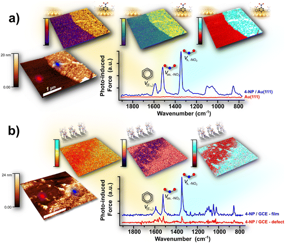 |
| | Fig. 2 The clean template-stripped gold (tsAu) interface functionalized with a 4-nitrophenyl (4-NP) nanofilm, produced via localized electrochemistry using SECCM (a). The strong infrared signals of the 4-NP nanofilm, measured by PiFM, show high-intensity regions that align precisely with the film topography. Adapted from ref. 50, with permission from the American Chemical Society. A 4-NP nanofilm was also deposited on a glassy carbon electrode (GCE) surface (b). Although the PiFM signal was notably weaker than on the tsAu substrate, mid-infrared spectra clearly distinguished between sparsely populated pinholes and more densely coated areas. PiFM mapping further revealed contrast in signal intensity between these features. Adapted from ref. 51, with permission from the American Chemical Society. | |
2.2 PiFM of organic mixed ionic–electronic conductor films
Organic mixed ionic–electronic conductors (OMIECs) are typically thin polymeric films immersed in liquid electrolytes, serving as active layers in organic electrochemical transistors (OECTs). These materials have found wide application in sensing and bioelectronics,52–54 electrochromics,55,56 energy devices,57,58 and integrated circuits.59–61 Depending on their semiconducting type (p- or n-type), either holes or electrons modulate the oxidation state of the polymer repeating units. This redox process enables solution ions to associate with the charged states, thereby generating charge carriers and enhancing OMIEC conductivity.
A key challenge in the field, highlighted by Jackson et al., is the markedly lower performance of n-type OECTs compared to p-type devices. This difference often approaches nearly an order of magnitude when evaluated using the common figure of merit: the product of electronic mobility (μ) and volumetric capacitance (C*).62 To address this, the authors blended two n-type conjugated polymers, NDI(biOE2)-T2 and N2200, which bear branched oligoglycol and branched alkyl side chains, respectively (Fig. 3a). They demonstrated that a 90![[thin space (1/6-em)]](https://www.rsc.org/images/entities/char_2009.gif) :10 blend yielded a twofold increase in μC* relative to pristine NDI(biOE2)-T2 (Fig. 3b).
:10 blend yielded a twofold increase in μC* relative to pristine NDI(biOE2)-T2 (Fig. 3b).
Importantly, PiFM revealed that increasing the N2200 content induced phase separation, which was detrimental to electronic performance (Fig. 3c). PiFM provided nanoscale chemical contrast, clearly evidencing the loss of film homogeneity caused by excess N2200 and its negative impact on μC*. Additional experiments showed that a controlled, small addition of N2200 reduced swelling of the oligoglycol side chains in the thin films. However, the authors cautioned that such improvements are not universal: blending N2200 with other oligoglycol-substituted polymers did not yield beneficial effects.
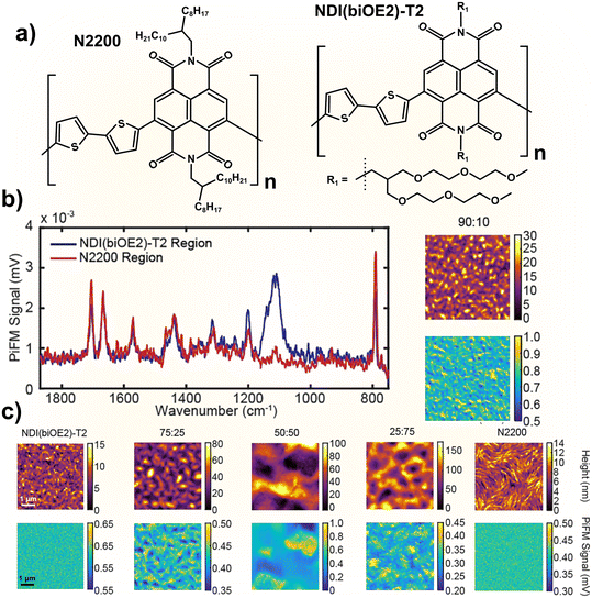 |
| | Fig. 3 Molecular structure of NDI(biOE2)-T2 and N2200 OMIEC polymers (a), PiFM spectra of the film surface with either greater NDI(biOE2)-T2 or N2200 signals (b), and PiFM images of pure or different ratio blended films clearly showing that the 90:10 ratio produces a more seamlessly mixed blend with less aggregated domains in comparison to the biphasic solid chemical heterogeneities observed in the other resulting mixtures (c). Adapted from ref. 62, with permission from Wiley. | |
2.3 PiFM of silanized glass
Glass is a widely used material due to its abundance, transparency, and strength. However, during fabrication, glass often suffers a loss of mechanical strength from microdefects and machining imperfections.63 Numerous reinforcement methods have been explored, but while effective, they often compromise transparency, or they offer only marginal improvements.64 Drawing inspiration from nacre, the resilient inner shell layer of mollusks, we developed a glass composite that significantly enhances performance, surpassing annealed glass by 4300% in strength, 350% in fracture toughness, and 400% in impact resistance.65 Surface silanization further improved the optical properties, reducing haze by approximately 60% compared to untreated glass. PiFM was essential in analyzing these modified glass microflake surfaces, allowing a detailed topographical assessment across varying degrees of silanization (0%, 20%, and 100%) (Fig. 4b). Initial comparisons highlighted distinct surface topographies: untreated glass displayed a mostly smooth surface with minimal aberrations, while 20% silanized glass retained this flat character but featured regularly spaced nanodots. In the 100% treated sample, these nanodots had merged, creating a continuous layer over the glass surface with some larger particle formations. Mid-infrared PiFM spectra acquired from each sample showed an intensifying peak at ∼1710–1740 cm−1 that correlated with the silane concentration (Fig. 4a), confirming the presence of silanization. Topographical PiFM mapping at this peak revealed two distinct intensity populations on the 20% silanized sample, verifying the chemical identity of the nanodots. In contrast, a minimal signal was detected for the 0% sample, while the 100% silanized sample nearly showed a fully saturated signal, consistent with no coverage and full silane coverage, respectively.
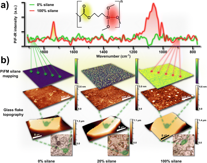 |
| | Fig. 4 Mid-infrared PiFM spectra recorded on the bare (0%) and fully (100%) silanized microglass flake surfaces, with ester and siloxane functional groups highlighted, respectively in yellow and red, on the TMSPMA molecular structure representation and in the averaged nano-IR spectra (a). Optical microscopy images, AFM, and PiFM analyses of microglass flakes silanized at 0%, 20%, and 100% revealed nanotopographical features associated with silane functionalization. PiFM mapping, focused on the ester functional group resonant mode highlighted in yellow (∼1710–1740 cm−1), enabled chemical identification and correlation of these features with surface functionalization (b). Adapted from ref. 65, with permission from Wiley. | |
2.4 PiFM of solar cells
Over recent decades, solar cell technology has advanced rapidly, moving from traditional silicon-based photovoltaics (PVs) to the versatile, third-generation devices constructed with organic, sensitized, and perovskite materials.66,67 Bulk heterojunction organic solar cells (BHJ-OSCs), pioneered in 1995, have seen impressive efficiency gains, although pushing these efficiencies further now requires a nuanced approach to controlling photon absorption, charge separation, and charge transfer processes.68 These factors influence critical parameters such as open-circuit voltage (Voc), short-circuit current density (Jsc), and fill factor (FF). Fullerene-based donor/acceptor (D/A) blends are a staple in OSCs.69 The development of high-performance, non-fullerene OSCs is still a frontier with considerable potential. Our previous work demonstrated that incorporating a third component with specific band-edge alignment can bridge donor and acceptor domains, facilitating charge separation and significantly enhancing power conversion efficiency (PCE).41 PiFM provided an unprecedented nanoscale view, revealing that this third component was not only essential but directly influenced the nanoscale blend morphology, which in turn impacted device performance. In this study, we focused on a ternary blend system, combining PBDB-T and ITIC-4F as the D/A pair with the addition of PDI-EH as the third component70 (Fig. 5c). By recording PiFM maps at unique bands specific to each D/A pair measured by FTIR spectroscopy (Fig. 5b), we captured the critical role of PDI-EH in achieving uniform domain sizes (10–20 nm) in the dried form of the active layer. PiFM results showed that a dosed addition of PDI-EH in the active layer blend effectively enhanced film homogeneity by suppressing isolated aggregates of PBDB-T and ITIC-4F, a result unattainable through conventional imaging techniques (Fig. 5a). Moreover, by adjusting PDI-EH concentrations, we observed how fine-tuning interlacing between D/A molecules could optimize PV performance and device efficiency. These findings underscore the potential of PiFM to not only characterize but also guide the development of advanced OSCs, where even subtle nanoscale adjustments can yield substantial performance gains. PiFM mapping of PBDB-T (at 1641 cm−1) and ITIC-4F (at 1540 cm−1) as a function of PDI-EH content revealed that a 20% PDI-EH concentration yielded the most colocalized distribution of the donor–acceptor pair. In contrast, blends containing 0%, 10%, or 50% PDI-EH exhibited noticeably poorer spatial overlap between donor and acceptor domains.
 |
| | Fig. 5 Blended bulk heterojunction (BHJ) topography, PiFM and combined PiFM maps of PBDB-T: ITIC-4F organic solar cell active layers prepared with varying concentrations (0%, 10%, 20%, and 50%) of the PDI-EH additive (a). Distinct ITIC-4F and PBDB-T film peaks were chosen from FTIR spectra to yield PiFM maps free from mixed signals (b). Z-scheme of the electron and hole mobility across the active organic layer (c). Enhanced device performance at 20% PDI-EH is attributed to improved miscibility between the donor (D) and acceptor (A) materials, promoting more optimal nanometer-level overlap. Lower (0%, 10%) and higher (50%) additive concentrations led to poor D/A phase blending, while the moderate 20% concentration achieved a homogeneous distribution and effective colocalization of D and A molecules. The combined mapping images reveal these respective variations in nanoscale heterogeneity and homogeneity. Adapted from ref. 70 with permission from the Royal Society of Chemistry. | |
2.5 PiFM of sensors
Rheumatoid arthritis (RA) is a prevalent autoimmune disease that causes painful inflammation in synovial joints, ultimately leading to bone erosion.71–73 This condition arises from an adaptive immune response that persistently activates T-cells through the CD28-B7 pathway.74,75 CD28, a membrane receptor on T-cells, binds strongly to CD80 and CD86 glycoproteins on the surface of activated antigen-presenting cells (APCs). A soluble form of CD80 (sCD80) is present in the circulation of both healthy individuals and those with autoimmune disorders.76–78 Although its exact role remains unclear, elevated sCD80 levels have been observed in patients with autoimmune diseases such as hematological malignancies and systemic lupus erythematosus (SLE).76,78 Studies have shown that RA patients treated with anti-inflammatory drugs exhibit reduced sCD80 serum levels, highlighting its potential as a preventive biomarker for RA.79,80 Currently, sCD80 is primarily quantified using an ELISA-based assay.81 However, the similarity between sCD80 and other co-stimulatory proteins leads to unavoidable cross-reactivity. Meanwhile, ELISA assays are costly and resource-intensive. Aptamers offer several advantages over antibodies: they are smaller, more stable, highly reproducible, and more cost-effective.82,83 Furthermore, aptamer candidates can undergo an iterative synthetic selection to identify sequences with optimal target binding, a process that is not feasible with antibodies. In this study, we developed an electrochemical aptamer-based biosensor (aptasensor) using commercially available screen-printed gold electrodes (AuSPEs).84 The DNA aptamer-functionalized surface was identified by its vibrational signatures corresponding to the phosphodiester backbone (∼875 cm−1), sugar-phosphate groups (∼1050 cm−1), C–X nucleotides (∼1730 cm−1), and base-sugar moieties (∼1100–1400 cm−1). In contrast, the amide I, II, and III bands served as effective markers for the sCD80-bound aptasensor by broadening, intensifying and shifting in the ∼1600–1750 cm−1 range, incurring weak peaks at ∼1525 cm−1, and causing several sharp bands between ∼1100–1400 cm−1 (Fig. 6a). These vibration modes enabled mapping of the spatial distribution of bioelements in their bound and unbound states on the biosensor surface by selecting appropriate wavebands. For instance, protein amide bands are known to shift depending on their chemical environments.85 We observed a similar phenomenon with the DNA aptamer, which showed that sCD80 bound and unbound aptamers had chemically separable phosphodiester chain signals. A neighboring sharp and intense peak was observed after the conjunction between DNA-aptamers and sCD80 proteins at ∼875 cm−1. The band at ∼1400 cm−1 was chosen to effectively map the DNA-aptamer at the base sugar resonance, and subsequently the sCD80 analyte's distribution on the biosensing surface at the amide III mode (Fig. 6b). PiFM played a crucial role in verifying surface coverage of the bio-recognition elements (REs) and visualizing RE–analyte complexes at various stages of aptasensor fabrication and after analyte exposure (Fig. 6c). Surface characterization by PiFM was imperative for understanding the aptasensor's superior sensing performance in terms of both sensitivity and stability in detecting sCD80.
 |
| | Fig. 6 Representative PiFM biosensor sample surface nanospectroscopy results show the DNA aptamers' and the proteins' detected mid-infrared vibrational modes (a). Perspective view topography and PiFM mapping of the aptasensor surface at different stages: bare AuSPE, AuSPE coated with the DNA aptamer, and coated with the DNA aptamer after exposure to the sCD80 analyte (b). The PiFM maps shown herein were specifically locked on the DNA aptamer via the base-sugar vibration mode and on the sCD80 protein via the amide III band at ∼1400 cm−1, as highlighted in (a). AuSPE schemes illustrating the Au working electrode conditions at the steps of the biosensor fabrication examined by PiFM (c). Adapted from ref. 84, with permission from Elsevier. | |
3. PiFM of rougher samples
In previous work, we conducted PiFM on relatively flat surfaces, characterized by height variations of less than 100 nm or with surfaces of regular geometry. On these samples, the tip operated at a controlled distance of 1–10 nm above the surface (85% setpoint) with a gentle dither of 1 nm amplitude and with a laser pulsing at fm = f1 − f0. However, some of these parameters are incompatible with samples featuring irregular structures of micrometer-scale heights. The resulting topography produces an inaccurate depiction of the actual surface due to uneven attractive forces pulling on the cantilever, triggering setpoint threshold distances that are too far from the true surface. Consequently, achieving accurate imaging on such samples requires switching from a contactless to a more dynamic (or tapping) mode (Fig. 1d). The excitation dither (Δ) was changed to 40 nm amplitude, but the laser frequency (fm) was conserved. In conventional PiFM, often termed the “second mode”, the lock-in amplifiers assign f0 to the PiF channel and f1 to the topography channel. For rougher samples, these assignments are reversed: f0 becomes the topography readout and f1 corresponds to the PiF signal, a configuration referred to as the “first mode”. This “first mode” is likewise used for sSNOM measurements. These adjustments are essential for the tip to overcome attractive forces from taller features, allowing it to temporarily enter the repulsive regime, where it effectively senses the surface and captures an accurate topography, rather than a misrepresentation of rough or heterogeneous surfaces. Although measurements remained surface-sensitive when using this setting, the lateral resolution and depth probed were likely to slightly deviate from conventional surface-sensitive measurements on smooth samples. These values are estimated to approach typical measurements done with tapping-mode AFM-IR, PFIR, and PTIR. Yet with this approach, we successfully obtained high-quality topography frames along with sub-diffraction chemical contrast data. We acquired clean mid-infrared spectra and chemical mapping images for diverse samples, including cellulose nanofibril (CNF) and amyloid protein (CsgA) bionanocomposite films, MON and COF powders, and wood modified with disodium octaborate tetrahydrate (DOT).
3.1 PiFM of cellulose nanofibril and amyloid protein bionanocomposites
With growing environmental and health concerns, there is a rising demand for biodegradable and biocompatible materials in fields like food packaging and healthcare.86–92 Among various candidates, polysaccharide–protein composites show promise as biocomposites with practical physicochemical and mechanical properties.93 Such biocomposites have been utilized in various applications, including water treatment, molecular biology, adhesives, and antimicrobial activity.94–98 Naturally occurring proteins, such as silk and collagen, have demonstrated significant improvements in bionanocomposites, enhancing mechanical strength, wettability, thermal stability, electrical properties, and optical characteristics.97,99 While amyloid fibrils are traditionally associated with disease, recent studies reveal that amyloid proteins serve essential functions across various organisms.100,101 Research combining polysaccharides with amyloid proteins has demonstrated that, even when the proteins are not inherently amyloidogenic, the resulting composites still exhibit enhanced mechanical strength and thermal tolerance compared to the raw materials. Cellulose, the most abundant polysaccharide, can be processed into cellulose nanomaterials (CNMs). One such CNM, cellulose nanofibril (CNF), has an elastic modulus of several hundred GPa and a diameter of only a few nanometers. In this study, we combined CNFs with CsgA, an amyloid protein naturally produced from the csgA gene in E. coli, which has an elastic modulus of 3–20 GPa, making it one of the stiffest known biopolymers.102,103 With goals of fusing the beneficial environmental, mechanical and thermal properties of both materials, we fabricated ∼500 μm-thick free-standing films of this CsgA–CNF bionanocomposite, hypothesizing that the nanometer-scale fibrils of CsgA and CNFs would yield a highly interlaced blend at the nanoscale.104 We examined bare CNF, BSA–CNF, and CsgA–CNF films by energy-dispersive X-ray (EDXS), X-ray photoelectron (XPS), and FTIR spectroscopies that unequivocally confirmed the incorporation of protein within the blended CNF films (Fig. 7a). Thermogravimetric analysis (TGA) further supported that the embedded protein imparted its physicochemical properties to the CNFs, notably enhancing their thermal stability and hydrophobicity. Moreover, TGA pointed out that the CsgA–CNF had greater moisture retention properties in comparison to bare and BSA supplemented CNFs, suggesting a surface hydrophobic coating which comparatively delayed the release of steam. Collectively, mid-infrared PiFM intensity contrast imaging and spectroscopy provided key understanding of the overall structure of these free-standing films by integrating the information from multiple data sources. PiFM chemically differentiated proteinaceous and cellulosic components at the film surface with sub-diffraction-limited resolution to show that in contrast to BSA, which was homogeneously dispersed within the bulk of the CNF film, CsgA aggregated domains assembled almost exclusively at the surface (Fig. 7b). Following protein inclusion, amide I and II bands appeared in the bare CNF mid-infrared spectra, with considerably stronger signals originating from the CsgA–CNF surface (Fig. 7c). The spectral features further indicated that the protein aggregates were dominated by antiparallel β-sheet structures and contained minimal α-helical content. As expected, the topography images and PiFM maps were consistent with one another, reflecting the surface-localized aggregation of the amyloid fibrils. Notably, localized PiFM point spectra showed that high-intensity pixels exhibited stronger amide I and II peaks than low-intensity regions. Moreover, the tallest topographic features did not systematically coincide with high PiFM-intensity pixels, and vice versa, confirming that the PiFM maps faithfully represented the distribution of CsgA on the composite surface. Altogether, this expanded characterization suite provided robust insight into the molecular interactions between the polysaccharide scaffold and the amyloid protein modifiers, offering a novel PiFM-based method to analyze amyloid–nanocellulose bionanocomposites.
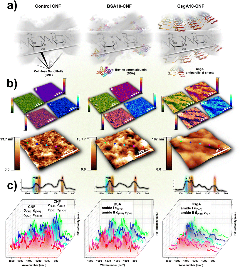 |
| | Fig. 7 Schematic of the free-standing cellulose nanofibril (CNF) and protein bionanocomposite films (a). Topographical images of control CNF, BSA10–CNF, and CsgA10–CNF bionanocomposite films overlaid with corresponding PiFM chemical maps (b) at the annotated and highlighted spectral bands (labelled i–iv) on the smoothed and averaged PiFM mid-infrared spectra shown in inset in (c). Localized raw PiFM mid-infrared spectra recorded from CNF, BSA10–CNF, and CsgA10–CNF bionanocomposite film surfaces (c). PiFM distinctly contrasted between the CNFs and the embedded protein regions, emphasizing on their spatial distribution and interaction. Spatially resolved mid-infrared PiFM spectra revealed enhanced amide I and II protein signals on the surface of BSA10–CNF and CsgA10–CNF, compared to the CNF control. Adapted from ref. 104, with permission from the American Chemical Society. | |
3.2 PiFM of covalent organic frameworks and microporous organic networks
Organic molecules are at the forefront of recent advances in materials science, especially since the past decade, in the form of microporous organic networks (MONs) and covalent organic frameworks (COFs).105,106 Notably, the 2025 Nobel Prize in Chemistry was awarded to Susumu Kitagawa, Richard Robson, and Omar M. Yaghi for their pioneering work on metal–organic frameworks (MOFs). Yaghi also originated the concept of COFs, first reported in 2005.107 These polymers exhibit impressive thermal and chemical stability along with a highly porous structure, providing a large surface area ideal for applications in heterogeneous catalysis, phase separations, gas and energy storage, fiber coatings, and even molecular electronics and optoelectronics.108 MONs, often synthesized through the coupling of phenyl-based molecules under Sonogashira reaction conditions, form amorphous networks. At the same time, COFs and functionalized COFs are created using the Schiff base and transamination reactions in solvothermal environments to achieve high crystallinity and uniform pore sizes.106,109–115 The crystalline quality of COFs is achieved through a thermodynamic assembly–disassembly cycle: the more extensive the cycles, the greater the reconstruction from the fast amorphous kinetic products to the slow crystalline thermodynamic products, resulting in a more stable and higher-quality COF structure.116,117 The various topologies of COFs can be precisely designed based on the monomeric coordination numbers, resulting in two-dimensional or three-dimensional geometries such as triangles, squares, hexagons, or tetrahedra, respectively.118 In our work, we designed MON and COF materials with a focus on reusability. We created core–shell structures with a magnetic Fe3O4 core coated by an amorphous MON shell or functionalized crystalline COFs, providing stability and allowing for easy recovery of the material using an external magnet. The outer organic layer was embedded with metal nanoparticles (MNPs), conferring catalytic or binding functionalities and enabling efficient separation without decomposition or leaching. Specifically, we synthesized copper and copper oxide nanoparticle-modified MONs as dual-purpose catalysts for converting CO2 into cyclic carbonates, presenting a green solvent alternative to toxic reagents.119 PiFM confirmed particle diameters measured by electron microscopy, ranging from 300 to 500 nm, and successfully resolved the Fe3O4 core from the organic MON shell. The mid-infrared PiFM spectra were consistent with previously recorded FTIR data for this material. Aromatic and aromatic amine peaks were observed at ∼1000–1150 cm−1, 1259 cm−1, and near 1600 cm−1, while C–N vibrations appeared at 1511 cm−1. Upon incorporation of Cu NPs, hypsochromic shifts of the aromatic–NH2 and C–N bands indicated successful interactions with MON matrix amine groups. PiFM mapping at the C–N band produced a uniform high-intensity image, confirming a homogeneous surface distribution (Fig. 8b). Similarly, Pd NP-modified MONs were developed as heterogeneous nanocatalysts for Suzuki and Sonogashira C–C bond-forming reactions to synthesize biaryls.120 PiFM metrology established particle sizes and confirmed the chemical identity of the MNP-MON base. Mid-infrared spectra revealed the integration of Pd NPs into the MON shell through blue shifts of the aromatic–NH2 (∼1260 cm−1) and C–N (∼1510 cm−1) bands to ∼1265 cm−1 and 1518 cm−1, respectively. Mapping of the C–N band further confirmed the uniform surface distribution of Pd NPs (Fig. 8c). An amine-functionalized COF with high affinity for mercury ions was also synthesized, highlighting its potential for water treatment applications.121 PiFM topography indicated that larger Fe3O4-COF structures were surrounded by smaller spherical counterparts. Mid-infrared spectra captured the transformation from bare Fe3O4@COF to Fe3O4@RCOF-EBH-TSC, marked by the disappearance of the imine (C![[double bond, length as m-dash]](https://www.rsc.org/images/entities/char_e001.gif) N) peak at ∼1625 cm−1 and the emergence of a C–N peak at 1250 cm−1, reflecting the successful reduction of imines to amines (Fig. 8a). More recently, we demonstrated an environmentally beneficial application using MON-coated MNPs to selectively recover precious metals, notably gold, from electronic waste.122 PiFM topography showed minimal morphological changes post Au NP binding, aside from slight particle shrinkage. Mid-infrared spectra identified these features as MON materials via the intense aromatic peak at ∼1500 cm−1, and mapping at this frequency corroborated the surface distribution. While the far-infrared Au–S resonance was not accessible by PiFM, shifts toward higher frequencies indicated modifications in the MON shell chemical environment following Au NP incorporation (Fig. 8d). Furthermore, the interactions between crystalline COFs functionalized with ionic liquids and gold were investigated.123 PiFM mid-infrared spectra matched bulk FTIR, confirming uniform chemical identity at the nanometer scale. Triazole moieties were identified via secondary and tertiary amine C–N stretches, benzene ring modes, and imine (CN) vibrations at ∼1210 cm−1, 1374 cm−1, and 1565 cm−1, respectively. COF structures appeared as clusters of fractal polygons. Functionalization of COF-NHC led to broadening of existing signals, particularly aromatic and imine modes, and intensification of the C–N peak due to increased histidyl content. Upon Au binding (COF-NHC-Au), particle size decreased, and peak shifts, both hypsochromic and bathochromic, occurred while retaining original COF-NHC features, reflecting partial participation of COF-NHC molecules in Au coordination (Fig. 8e). PiFM proved essential in characterizing these materials, verifying the integration of metal NPs within the MON/COF matrices, the successful functionalization of the COF materials, and the morphological and spectral effects after capturing gold. This powerful technique was crucial for confirming the structural and chemical composition of our hybrid materials systems, ensuring they met the required stability and functionality claims.
N) peak at ∼1625 cm−1 and the emergence of a C–N peak at 1250 cm−1, reflecting the successful reduction of imines to amines (Fig. 8a). More recently, we demonstrated an environmentally beneficial application using MON-coated MNPs to selectively recover precious metals, notably gold, from electronic waste.122 PiFM topography showed minimal morphological changes post Au NP binding, aside from slight particle shrinkage. Mid-infrared spectra identified these features as MON materials via the intense aromatic peak at ∼1500 cm−1, and mapping at this frequency corroborated the surface distribution. While the far-infrared Au–S resonance was not accessible by PiFM, shifts toward higher frequencies indicated modifications in the MON shell chemical environment following Au NP incorporation (Fig. 8d). Furthermore, the interactions between crystalline COFs functionalized with ionic liquids and gold were investigated.123 PiFM mid-infrared spectra matched bulk FTIR, confirming uniform chemical identity at the nanometer scale. Triazole moieties were identified via secondary and tertiary amine C–N stretches, benzene ring modes, and imine (CN) vibrations at ∼1210 cm−1, 1374 cm−1, and 1565 cm−1, respectively. COF structures appeared as clusters of fractal polygons. Functionalization of COF-NHC led to broadening of existing signals, particularly aromatic and imine modes, and intensification of the C–N peak due to increased histidyl content. Upon Au binding (COF-NHC-Au), particle size decreased, and peak shifts, both hypsochromic and bathochromic, occurred while retaining original COF-NHC features, reflecting partial participation of COF-NHC molecules in Au coordination (Fig. 8e). PiFM proved essential in characterizing these materials, verifying the integration of metal NPs within the MON/COF matrices, the successful functionalization of the COF materials, and the morphological and spectral effects after capturing gold. This powerful technique was crucial for confirming the structural and chemical composition of our hybrid materials systems, ensuring they met the required stability and functionality claims.
 |
| | Fig. 8 PiFM spectra confirmed the successful functionalization of RCOF-EBH into RCOF-EBH-TSC, indicated by the disappearance of the CN stretching peak and the emergence of –OH and C–N stretching signals, with no significant changes in topography (a). Adapted from ref. 121, with permission from the American Chemical Society. A magnified view of the MON PiFM spectra (inset) revealed key blue shifts in the aromatic–NH2 and C–N peaks after the incorporation of Cu nanoparticles (b). Adapted from ref. 119, with permission from Elsevier. Similar peak shifts were observed following the addition of Pd nanoparticles to the MON shell, and after Au recovery from e-waste (c and d). Adapted from ref. 120 and 122 with permission from the American Chemical Society. A PiFM scan at the C–N signal showed a high degree of overlap between the signal and the topographically imaged particles (b and c). The PiFM scan showed an increase in signal after the Au bound to MON, possibly caused by the plasmonic effect of Au NPs enhancing the PiFM signal (d). Although the signals remained constant, apparent peak shifts were observed after the COF-NHC was bound to gold (e). Adapted from ref. 123, with permission from the American Chemical Society. | |
3.3 PiFM of metal–organic frameworks
An interesting application of PiFM has recently been reported in the study of adsorption properties on metal–organic framework (MOF) surfaces. Delen et al. investigated different facets of ZIF-8 microcrystals exposed to formaldehyde at various partial pressures124 (Fig. 9a and b). They found that adsorption occurred predominantly on higher-index crystallographic planes, mainly at the corners and edges of the microcrystals, which are only a few tens of nanometers in size within otherwise micrometer-sized structures. Additionally, isolated high-energy nanodomains within low-energy facets enabled adsorption on the basal planes. Defects introduced by pyrrole ligands were shown to preferentially target these high-energy nanodomains. Based on these observations, the authors proposed two distinct mechanisms of formaldehyde adsorption (Fig. 9d). The technical significance of this work lies in the demonstration of in situ adsorption measurements under vacuum and the use of hyperspectral imaging (Fig. 9c). Although operating PiFM under vacuum presents challenges, including potential interferences in the chamber environment and the fact that commercial PiFM probes are optimized for ambient rather than vacuum conditions, the authors successfully adapted the technique to reliably differentiate anisotropic adsorption effects. Hyperspectral imaging, another unique capability of PiFM, links each topographic pixel to a corresponding PiFM spectrum. While this mode is inherently time-consuming due to the need for long acquisition times (typically 20–30 s per spectrum), the authors demonstrated that reliable spectra can be obtained with much shorter acquisitions (100–400 ms per spectrum), enabling practical imaging. To balance quality and speed, they employed 64 × 64 px2 resolutions, which allowed acquisition within reasonable timeframes while still yielding interpretable data.
 |
| | Fig. 9 ZIF-8 MOF structure schematically represented (a), a ZIF-8 microcrystal drawing showing the different crystallographic planes and a PiFM probe scanning the surface in situ while formaldehyde is being adsorbed (b). Hyperspectral images captured on the same frame at varying formaldehyde partial pressures. Spectra show the –CH2 bending and C–O stretching signals as an indicator of formaldehyde adsorption (c). Author-proposed adsorption and conversion mechanisms of formaldehyde on ZIF-8 microcrystals (d). Adapted from ref. 124 with permission from Springer Nature. | |
3.4 PiFM of twisted organic crystals
Organic crystals are at the very foundation of molecular optical phenomena, a legacy tracing back to Louis Pasteur's pioneering observations on the optical activity of tartaric acid crystals.125–127 Decades later, organic crystals have resurfaced as materials of great interest, not only for their optical properties but also for their diverse morphologies and mechanical behaviors. In particular, flexible organic crystals capable of bending and twisting hold significant promise for applications in optoelectronics,128–131 mechanophotonics,132–134 soft robotics,135,136 and smart sensing.137 While lattice defects responsible for such phenomena are well documented in inorganic crystals, they remain rare and insufficiently explored in organic crystalline materials. This scarcity highlights a pressing need to deepen our understanding of the mechanical, structural, physical, and chemical characteristics of deformable organic crystals. A recent study by Tang et al. investigated the origins of twisted and bent morphologies during the crystallization of the minor tautomer of ammonium urate (NH4HU).138 Crystals were obtained through pH adjustment without the application of any external mechanical stimuli. Interestingly, only crystals grown at neutral pH exhibited bending and twisting, with increasing NH4HU concentrations further amplifying these deformations and generating more complex motifs such as loops. High-resolution scanning electron microscopy (SEM) (Fig. 10a), transmission electron microscopy (TEM), and nano-electron diffraction (NED) (Fig. 10c) revealed the coexistence of multiple crystalline facets (Fig. 10b). Sequential TEM analyses revealed that random defects, screw dislocations, and edge defects were key contributors to the observed morphologies. PiFM played a crucial role in this study, providing nanoscale chemical insight into how the urea functional groups experienced different chemical environments in bent and twisted crystals compared to straight, linear ones. From the concave to the convex regions of curvature, PiFM spectra exhibited both broadening and intensity loss in the N–H wagging and aromatic π–π interaction bands, accompanied by a distinct CO blueshift, clearly evidencing strain-induced modification in molecular bonding and local environments (Fig. 10d).
 |
| | Fig. 10 SEM micrograph showing intertwined networks of NH4HU minor tautomer crystals, distinguishable by their curved morphology. A magnified view of a single crystal reveals the presence of twisting along its structure (a). The facets of the twisted crystals were indexed using TEM tomography (b). TEM image with NED patterns collected at three different locations along a curved NH4HU crystal fiber (c). PiFM topography and corresponding chemical maps acquired at the N–H wagging band (1397 cm−1) and the C–N stretching band (1009 cm−1), associated with aromatic π–π interactions (d). While the straight microcrystals exhibited homogeneous signals, the bent and twisted structures displayed pronounced chemical contrast between the concave and convex sides, indicating distinct local chemical environments. Adapted from ref. 138 with permission from Proceedings of the National Academy of Sciences. | |
3.5 PiFM of DOT-treated wood
Earthen construction is one of the oldest and most sustainable architectural methods, offering communities cost-effective housing with a minimal environmental impact.139–141 Wood serves as the primary foundation material in these constructions, but untreated wood is highly vulnerable to degradation from insects, fungi, algae, and fire, leading to significant decay.142 Advances in technology and industry standards now guide the processing of lumber for construction, with building codes, such as the widely adopted International Building Code, mandating that wood be treated for both safety and longevity.143 Common wood treatments include tars, oils, organic fungicides, silicates, copper salts, and boric acid salts.144–147 Among these, borates are especially valued in construction for their dual role as wood preservatives and flame retardants.146,148,149 While large-scale applications of borates, such as DOT, can be conveniently achieved through dipping methods, these compounds are prone to leaching into the environment.150 Fortunately, borates are eco-friendly and pose minimal risk when released into natural waterways.151,152 Our study addresses the need for enhanced treatment longevity by investigating methods to improve borate retention within the wood matrix. We focused on the permeation behavior of DOT, an area that, until now, has lacked in-depth examination.153 Our findings provide new insights into DOT's potential as a reliable and effective wood treatment (Fig. 11a). Using depth concentration profiling and interfacial measurements, we mapped DOT displacement in realistic scenarios, such as at the wood/clay boundary in earthen structures. Both bulk analytical measurements and localized surface infrared spectroscopy were critical for chemically visualizing the effects of DOT treatment. FTIR spectra of treated fir and spruce revealed systematic signal enhancements in the 1000–1475 cm−1 region, attributed to the characteristic contributions of boric acid at 1150 cm−1 and 1429 cm−1 (Fig. 11c).154 These spectral changes were mirrored in the PiFM mid-infrared measurements (Fig. 11d). Notably, the peak at 1750 cm−1 exhibited stronger enhancement in spruce compared to fir following DOT application. Because DOT is slightly alkaline, it raises the pH, which may promote alkaline-mediated oxidation or hydrolysis of hemicellulose, cellulose, and lignin, providing a plausible explanation for the observed peak intensification.155 The relatively modest enhancement in fir suggests that this wood species was already more oxidized than spruce prior to treatment, and DOT only subtly promoted further oxidation. Initially pronounced oxidation in fir also suggests a greater intrinsic susceptibility to ambient oxidation compared to spruce. Overall, combining PiFM with quantitative lateral migration measurements and bulk infrared spectroscopy enabled high-resolution analysis of DOT interfacial dynamics. This approach allowed both qualitative comparison of surface chemistry and quantitative assessment of time-dependent DOT migration, as influenced by humidity and a clay sealant coating, across the two wood types, providing detailed chemical imaging insights (Fig. 11b).
 |
| | Fig. 11 Schematic of disodium octaborate tetrahydrate (DOT) functionalization of wood (a). PiFM topography of diced fir and spruce samples along the grain axis, with corresponding PiFM maps at ∼1096 cm−1, selectively visualizing DOT treatment effects on the surface (b). Bulk FTIR spectra in the 900–1200 cm−1 range showing generalized mid-infrared intensity increases due to DOT functionalization, with pronounced sensitivity at ∼1096 cm−1 (c). PiFM mid-infrared spectra pointing at intensifications at ∼1100 cm−1 and ∼1425 cm−1; the highlighted ∼1096 cm−1 band was selected for surface PiFM mapping (d). An additional intensification at 1750 cm−1 was observed in DOT-treated spruce spectra. Adapted from ref. 153 with permission from Wiley. | |
4. PiFM in bulk mode
Photoinduced force microscopy (PiFM) distinguishes itself from other AFM-IR techniques by offering superior surface sensitivity and finer lateral resolution, particularly in sideband operation, where the infrared laser pulse frequency is tuned to the difference between the first and second eigenmodes of the cantilever. Beyond this conventional configuration, PiFM also enables a less-explored mode for probing deeper into materials, facilitating “bulk-type” investigations. In this direct mode, the infrared laser is pulsed at the same frequency as the first cantilever vibration mode (fm = f0) (Fig. 1e). While the dither piezo (Δ) continues to oscillate the cantilever at 1 nm amplitude, the probed depth (d) extends significantly beneath the surface.32,33 In direct mode, the lock-in amplifiers are configured as in conventional sideband non-contact PiFM, corresponding to the “second mode”. Using this deep-mode configuration, we successfully visualized graphene oxide flakes embedded below the micrometer surface of a proton exchange membrane water electrolyzer (PEMWE),156 and near hundreds of nanometer thick films of silanized glass substrates before and after undergoing “click” chemistry to produce superhydrophobic surfaces.157 It is noteworthy that PiFM in direct mode is not the most commonly used configuration, as most studies focus on surface-sensitive sideband operations to probe interfacial features. The measurements presented here are therefore original, representing one of the few demonstrations of bulk-sampling PiFM while retaining sub-diffraction lateral resolution. We successfully probed sample thicknesses ranging around 250 nm and the top ∼1 μm within a 20 μm layer in two independent studies, as discussed below.
4.1 Graphene oxide embedded in Nafion for PEMWE applications
As renewable hydrogen emerges as a viable clean energy alternative, sustainable methods for its storage and production are undergoing rigorous investigation.158–160 Among these, electrically operated proton exchange membrane water electrolyzers (PEMWEs) present an attractive pathway due to their safety, scalability, lower energy demands, and enhanced productivity stemming from faster electrode kinetics.161–163 Perfluorosulfonic acid (PFSA) membranes, such as Nafion, are reference materials employed as the polymer electrolyte membrane in PEMWEs,164–166 owing to their stable and adequate mechanical, thermal, and chemical properties.160,167–172 Despite their robustness, PEMWE membranes are susceptible to chemical degradation from free radicals generated at the electrodes or metal leaching from cell components, which catalyze deleterious reactions.173–175 Mechanical failure due to hydration and temperature cycles represents another common challenge.176,177 These combined factors often lead to complete system failure.178,179 To extend device durability, researchers have developed ameliorated composite membranes by incorporating nanocarbons, such as multi-walled carbon nanotubes (MWCNTs) and graphene, into Nafion, primarily through solution casting techniques.168,180–188 However, solution casting methods present limitations in terms of scalability, reproducibility, and efficiency. Consequently, we designed a novel PEMWE membrane using ultrasonic spraying, a technique recognized for its ease of automation and capacity for large-scale production of uniform films through precise control over droplet sizes.189–191 Furthermore, graphene oxide (GO) is one of the least reported reinforcing agents in the literature, providing additional impetus to expand research with this nanocarbon, which holds significant potential for seamless performance.187,192–197 In this innovative work, we combined ultrasonic spraying with graphene oxide to fabricate a 20 μm nominal thickness protective GO–Nafion composite adlayer on the surface of commercially available Nafion 115 membranes (Fig. 12a).156 The resulting membrane was comprehensively characterized and tested under real-world conditions, demonstrating upgraded mechanical properties, increased thermal tolerance, enhanced hydrophilicity, unaffected electrochemical performance, and greater long-term stability. PiFM played a crucial role in elucidating the surface and bulk membrane characteristics influenced by graphene oxide loading. While the surface sensitive sideband PiFM measurements showed unchanged mid-infrared spectra on the control and on the GO-modified adlayer, PiFM intensity maps and spectra in the direct configuration successfully identified locations concealing graphene oxide flakes beneath the membrane surface (Fig. 12b and c). The results of this study supported experimental determination of micrometer PiFM depth sensitivity within the 20 μm adlayer in direct mode.
 |
| | Fig. 12 Schematic of the Nafion or Nafion–GO 20 μm protective adlayer on the PEMWE electrolyte membrane (a). PiFM direct-mode mapping at the –CF2– asymmetric stretching (∼1170 cm−1) and topography of both unmodified and GO-modified adlayer surfaces (b). PiFM direct-mode mid-infrared spectra at the indicated locations of the PiFM maps (c). PiFM spectra and mapping elucidated the in-depth distribution of graphene-oxide (GO) concealed within the GO-modified Nafion adlayer, indicated by lower PFSA intensity bands and areas of reduced intensity, respectively. For the bare Nafion sample, all spectra displayed uniform intensity, and the PiFM intensity mapping was consistent. Adapted from ref. 156, with permission from Elsevier. | |
4.2 Silane click chemistry for superhydrophobic surfaces
Natural phenomena have long inspired human imagination and technological progress, as exemplified by the self-cleaning properties of the lotus leaf.198,199 This biological blueprint has guided the design of superhydrophobic surfaces, where the observed behavior arises from a combination of mechanical structuring and chemical composition.200–207 Organosilanes represent one effective strategy for fabricating such surfaces, particularly on oxide substrates such as glass.208–211 In our recent work, we examined surface modifications of glass using allyltrichlorosilane (ATCS) and vinyltrichlorosilane (VTCS).157 These modifications were subsequently subjected to a thiol–ene click reaction with a long-chain alkyl thiol (1-DSH) to enhance surface hydrophobicity (Fig. 13a). PiFM was proven to be highly valuable for characterizing both functionalization steps and confirming the chemical identity of the molecular coatings. Because the resulting films were relatively thick (Fig. 13b), PiFM was operated in both sideband and direct modes to obtain complementary surface and depth-resolved chemical information (Fig. 13c). The average PiFM spectra collected before and after surface modification were integrated to quantify reaction efficiency (Fig. 13d). In parallel, ATR-FTIR-based calculations produced comparable results. However, both techniques indicated that the click reaction yield was substantially lower than previously reported near-quantitative yields in bulk solutions. Our findings suggest that PiFM provided a more detailed and discriminating view of the surface chemistry, enabling more precise differentiation between reacted and unreacted molecules, which may explain why earlier bulk studies overestimated yields. An additional factor is the availability of surface-exposed CC groups, which appears to be the limiting step in the reaction. Specifically, the nanofilamentous morphology of VTCS and the aggregated structures formed by ATCS reduced the accessibility of reactive CC bonds, thereby preventing near-quantitative yields. Based on cross-sectional SEM measurements of the ATCS layers, film thickness were estimated to be approximately ∼250 nm. These results experimentally demonstrate that PiFM in direct mode can effectively probe sample depths as thick as ∼250 nm and greater.
 |
| | Fig. 13 Hydroxylated glass surfaces were silanized with VTCS and ATCS, followed by a thiol–ene “click” reaction with a long-chain alkyl thiol (a). Topography images of the resulting VTCS coatings (b). PiFM chemical mapping of VTCS before and after the click reaction, showing sideband (surface) and direct (bulk) intensity distributions of C–C and CC bonds (c). The decrease in the CC signal at 1409 cm−1 is attributed to thiol–ene alkylation, while the corresponding increase in C–C intensity at 1467 cm−1 reflects the formation of new C–C bonds (d). Adapted from ref. 157 with permission from the Royal Society of Chemistry. | |
5. PiFM of surface-chemically modified 2D materials
Furthermore, we rigorously investigated the concept of atomic layer functionalization through PiFM using its highly sensitive non-contact mode, enriching prior findings with material-based reactivity and mechanistic insight in addition to providing definitive evidence of the localized optical properties of a successfully reduced aryl diazonium salt-functionalized 2D material surface.
Two-dimensional (2D) materials are marvels of materials science, particularly for their unique mechanical and optoelectronic properties, which enable highly efficient photovoltaic, electronic, optical, and energy devices that still challenge comprehensive theoretical understanding.212 Their designation as “2D materials” stems from their structure: atomically thin, flat surfaces that adhere to substrates through van der Waals interactions.213 Within this category, transition metal dichalcogenides (TMDCs) have garnered significant attention due to their exceptional electronic properties and ambient stability.214 TMDCs exhibit intriguing behaviors when isolated as a monolayer. For instance, monolayers possess a distinct band gap and charge conduction mechanism, with a typically higher and direct band gap compared to the indirect gap observed in few-layered structures.215 These properties render monolayer TMDCs highly promising for applications in semiconductor, optoelectronic, and molecular electronics sectors.216 Additionally, monolayer TMDCs can undergo phase transformation; for example, upon sufficient charge transfer, the ambiently stable semiconducting 2H phase may convert to a metastable metallic 1T phase.217 Exfoliating bulk TMDCs with strong reducing agents, such as tert-butyllithium (tBuLi), also yields conductive individual flakes. TMDCs are available naturally in bulk form; however, synthetic approaches, both top-down and bottom-up, have been developed to produce these materials. Bottom-up techniques are particularly appealing for the scalable and controlled production of large-area monolayers. Among these methods, chemical vapor deposition (CVD) is notably more cost-effective and scalable than molecular beam epitaxy (MBE). Recent studies have attempted to covalently modify TMDC surfaces using aryl diazonium salts (Fig. 14b). Still, many of these investigations inferred the presence of grafted molecules based on topographical or bulk spectroscopic assumptions, lacking definitive chemical evidence.218–232 In our work, we addressed this knowledge gap in using PiFM to provide clear, chemical evidence of monolayer TMDC functionalization (Fig. 14a), elucidating previous ambiguous claims and contributing valuable insights to the field.233 Additionally, we concluded that the observed signal contrast between TMDC materials on the functionalized lateral monolayer heterostructure arose from either differences in material-specific grafting reactivity or from varying surface signal enhancement effects (Fig. 14c).
 |
| | Fig. 14 PiFM mid-infrared spectra highlighting the infrared vibration modes of 4-NP (i–iii) recorded from locations marked with colored stars in the modified TMDC topography images (a). Schematic of the modified MoSe2, WSe2, and MoSe2–WSe2 in-plane lateral heterostructure TMDC monolayers modified with 4-NP molecules (b). Topography of bare and functionalized monolayer TMDCs and PiFM mapping images of the functionalized monolayer TMDCs showing greater PiFM-IR intensity at the 4-NP resonant modes on their structural domains, compared to the modified gold substrate, as observed with the intensities in the measured spectra (c). Adapted from ref. 233, the author's Ph.D. thesis. | |
6. Subnanometer resolved PiFM
It is well established that AFM topography images are inherently limited by the radius of curvature of the probe tip apex. In contrast, PiFM chemical mapping is not subject to this constraint, since the effective probe is not the physical tip itself but the near-field protrusion at the apex. This protrusion forms a conical tapered end that is significantly narrower than the geometric tip size. Despite this advantage, image quality remains sensitive to practical factors such as scanning stage piezoelectric crystal hysteresis, creep, and especially thermal drift. Additionally, friction between the probe tip and the surrounding air degrades the quality factor (Q) of the cantilever oscillation. Collectively, these limitations constrain the best achievable resolution to ∼5 nm. While this represents a major achievement in chemical vibrational microscopy, it still falls short of genuine molecular-level resolution. Visualizing individual molecules under ambient conditions remains particularly challenging and would require roughly half an order of magnitude further improvement in spatial resolution. Significant progress has nevertheless been achieved in recent years, most notably by Sugawara and co-workers, who have introduced PiFM to the subnanometer scale. In 2021, they reported single-nanometer resolution (∼0.7 nm) on Zn–Ag–In–S (ZAIS) quantum dot heterostructures (Fig. 15a).5 This innovation was made possible through the development of a custom-built PiFM system, granting complete control over instrumental parameters. The critical factors enabling this resolution included operating under ultrahigh vacuum (<5.0 × 10⁻⁹ Pa), the use of a highly sensitive cantilever (k ≈ 2 N m−1), and an exceptionally high Q factor of ∼35400. More recently, in 2024, the same group demonstrated molecular resolution down to 0.6 nm by imaging individual pentacene molecules under near-cryogenic conditions (Fig. 15b).7 In this case, lowering the temperature from ambient to 78 K (−195.15 °C) effectively suppressed thermal drift and molecular motion, granting unprecedented optical stability. Notably, PiFM was performed in conjunction with Kelvin probe force microscopy (KPFM), allowing simultaneous mapping of electronic and vibrational properties. This dual approach revealed how charge transfer across pentacene molecules modified local dipole distributions, in agreement with quantum chemical calculations. The authors further proposed that numerous picocavities formed at the sensing apex synergistically amplified the plasmonic near-field, thereby enhancing spatial resolution. Importantly, they confirmed that while these picocavities are beneficial for PiFM imaging, the overall tip shape does not introduce artifacts or “ghost images” in the acquired data.
 |
| | Fig. 15 PiFM setup scheme showing the side-illuminated tip over a ZAIS quantum dot. PiFM images and profile measurements showing the resolving power down to ∼0.7 nm (a). Adapted from ref. 5, with permission from Springer Nature. The PiFM setup scheme showing the tip over pentacene molecular structures. PiFM mapping of the pentacene covered surface and profile measurement showing the resolution at 0.6 nm. Theoretical quantum chemical calculations considered picocavities that amplified the near-field protrusion from the probe apex (b). Adapted from ref. 7, with permission from the American Chemical Society. | |
7. Conclusion
This comprehensible review highlights the remarkable versatility of PiFM in examining a diverse array of sample types. PiFM demonstrated sub-monolayer thickness sensitivity for organic molecules on gold and carbon surfaces, precise detection and chemical mapping of silane molecules on glass, variability in organic mixed ionic–electronic conductor (OMIEC) film nanograins or in donor–acceptor domain-size organic solar cell active layers, and the spatial distribution of DNA-aptamer recognition elements and protein analytes on biosensing devices. These results showcase PiFM's capabilities for contactless surface chemical detection and imaging on flat, smooth surfaces. Importantly, this work also addresses the limitations of the non-contact mode for rougher surfaces, introducing a tunable alternative in the form of a high-amplitude intermittent (tapping) mode at the attractive regime. This approach effectively overcomes imaging challenges, delivering nanometer-scale insights into surface chemistry that remain beyond the reach of diffraction-limited optical methods. Using this mode, we discussed and analyzed diverse samples such as cellulose nanofibril and intrinsic amyloidogenic protein bionanocomposites, the chemical and chelating effects of microporous organic networks (MONs) and covalent organic frameworks (COFs), metal organic framework (MOF) adsorption properties, local organic crystal chemical molecular environments, and boronic acid derivative-treated timber, revealing valuable connections between surface chemistry, modifications, and distinct physical properties. Furthermore, we demonstrated the utility of the often-overlooked direct-mode configuration for revealing graphene oxide flakes deeply embedded within a Nafion membrane and examining the depths of a silanized glass surface subjected to thiol–ene “click” chemistry. We then presented PiFM as a pioneering instrument capable of unifying and advancing knowledge in underexplored areas, such as the surface functionalization of transition metal dichalcogenides and their material-based reactivity using aryl diazonium salts. Finally, we briefly summarized high-end, precise sub-nanometer resolutions achieved with the PiFM under customized conditions, minimizing usual causes of noise and interferences. The advent of PiFM marks a checkpoint in scanning probe microscopy (SPM), unlocking valuable potential in materials interfaces and surface science. Looking ahead, the future of SPM holds promising opportunities, particularly with the potential integration of artificial intelligence and machine learning. Such advancements could empower mankind by building the next generation of instruments to measure surface chemistry with supreme accuracy and overcome a new level of sample preparation complexities, redefining the boundaries of technological innovation in surface characterization.
Author contributions
Conceptualization (M. J.; M. S.), data curation (M. J.), formal analysis (M. J.), funding acquisition (M. S.), investigation (M. J.), methodology (M. J.), project administration (M. S.), resources (A. K., M. S.), software (M. J.), supervision (M. S.), validation (M. J., A. K., M. S.), visualization (M. J.), writing – original draft (M. J.), writing – review and editing (M. J., A. K.).
Conflicts of interest
The authors declare no conflicts of interest.
Abbreviations
| 1-DSH | 1-Decanethiol |
| 4-NP | 4-Nitrophenyl |
| ATCS | Allyltrichlorosilane |
| APCs | Antigen presenting cells |
| AFM | Atomic force microscope (microscopy) |
| AFM-IR | Atomic force microscope (microscopy)-infrared |
| ATR-FTIR | Attenuated total reflectance Fourier transform infrared |
| BHJ-OSCs | Bulk heterojunction organic solar cells |
|
f
1
| Cantilever second mechanical eigenmode |
|
f
0
| Cantilever first mechanical eigenmode |
| CNFs | Cellulose nanofibrils |
| CNMs | Cellulose nanomaterials |
| CVD | Chemical vapor deposition |
| COFs | Covalent organic frameworks |
| DOT | Disodium octaborate tetrahydrate |
|
Δ
| Dither piezo oscillation amplitude |
| D/A | Donor/acceptor |
| EDXS | Energy-dispersive X-ray spectroscopy |
| ELISA | Enzyme-linked immunosorbent assay |
| FF | Fill factor |
| FTIR | Fourier transform infrared |
| GCE | Glassy carbon electrode |
| AuSPE | Gold screen printed electrodes |
| GO | Graphene oxide |
| 2H | Hexagonal |
| IR | Infrared |
| KPFM | Kelvin probe force microscopy |
|
f
m
| Laser modulation frequency |
| MNPs | Metal nanoparticles |
| MOFs | Metal–organic frameworks |
| MONs | Microporous organic networks |
| MBE | Molecular beam epitaxy |
| MoSe2 | Molybdenum diselenide |
| MWCNTs | Multi-walled carbon nanotubes |
| NED | Nano-electron diffraction |
| nanoIR | Nanometer infrared |
| NPs | Nanoparticles |
|
V
oc
| Open-circuit voltage |
| OECTs | Organic electrochemical transistors |
| OMIECs | Organic mixed ionic–electronic conductors |
| OSCs | Organic solar cells |
| PFIR | Peak-force infrared microscope (microscopy) |
| PFSA | Perfluorosulfonic acid |
| PIF | Photoinduced force |
| PiFM | Photoinduced force microscope (microscopy) |
| PTIR | Photothermal induced resonance |
| PVs | Photovoltaics |
| PCE | Power conversion efficiency |
|
d
| Probing depth |
| PEMWE | Proton-exchange membrane water electrolyzer |
|
Q
| Quality factor |
| REs | Recognition elements |
| REINS | Resonance enhanced infrared nanospectroscopy |
| RA | Rheumatoid arthritis |
| SECCM | Scanning electrochemical cell microscopy |
| SEM | Scanning electron microscopy |
| SPM | Scanning probe microscope (microscopy) |
| sSNOM | Scattering-scanning near-field optical microscope (microscopy) |
|
J
sc
| Short-circuit current density |
| S/N | Signal-to-noise ratio |
| sCD80 | Soluble CD80 |
| SLE | Systemic lupus erythematosus |
| TM-AFM-IR | Tapping-mode atomic force microscope (microscopy)-infrared |
| tsAu | Template stripped gold |
|
tBuLi |
tert-Butyllithium |
| 1T | Tetragonal |
| TGA | Thermogravimetric analysis |
| TMDCs | Transition metal dichalcogenides |
| TEM | Transmission electron microscopy |
| WSe2 | Tungsten diselenide |
| 2D | Two-dimensional |
| VTCS | Vinyltrichlorosilane |
| XPS | X-ray photoelectron spectroscopy |
| ZAIS | Zn–Ag–In–S |
Data availability
No new data were generated or analyzed in the preparation of this review manuscript.
Acknowledgements
We thank the Natural Science and Engineering Research Council of Canada (NSERC), the Canada Research Chairs (CRC) program, the Canada Foundation for Innovation (CFI), the Fonds de Recherche du Québec (FRQ) and the Quebec Center for Advanced Materials (QCAM).
References
- D. Nowak, W. Morrison, H. K. Wickramasinghe, J. Jahng, E. Potma, L. Wan, R. Ruiz, T. R. Albrecht, K. Schmidt, J. Frommer, D. P. Sanders and S. Park, Sci. Adv., 2016, 2, e1501571 Search PubMed
 .
.
- I. Rajapaksa, K. Uenal and H. K. Wickramasinghe, Appl. Phys. Lett., 2010, 97, 073121 Search PubMed .
- F. Zenhausern, Y. Martin and H. K. Wickramasinghe, Science, 1995, 269, 1083–1085 CrossRef CAS PubMed .
- I. Rajapaksa and H. Kumar Wickramasinghe, Appl. Phys. Lett., 2011, 99, 161103 Search PubMed .
- J. Yamanishi, H. Yamane, Y. Naitoh, Y. J. Li, N. Yokoshi, T. Kameyama, S. Koyama, T. Torimoto, H. Ishihara and Y. Sugawara, Nat. Commun., 2021, 12, 3865 CrossRef CAS PubMed .
- M. R. Shcherbakov, E. O. Potma, Y. Sugawara, D. Nowak, M. Stepanova, P. R. Davies, J. Davies-Jones and H. K. Wickramasinghe, Nat. Rev. Methods Primers, 2025, 5, 34 Search PubMed .
- T. Yamamoto, H. Yamane, N. Yokoshi, H. Oka, H. Ishihara and Y. Sugawara, ACS Nano, 2024, 18, 1724–1732 CrossRef CAS PubMed .
- J. Davies-Jones, P. R. Davies, A. Graf, D. Hewes, K. E. Hill and M. Pascoe, Nanoscale, 2024, 16, 223–236 Search PubMed .
- M. A. Almajhadi, S. M. A. Uddin and H. K. Wickramasinghe, Nat. Commun., 2020, 11, 5691 Search PubMed .
- D. S. Jakob, H. Wang, G. Zeng, D. E. Otzen, Y. Yan and X. G. Xu, Angew. Chem., 2020, 59, 16083–16090 Search PubMed .
- H. Wang, E. Janzen, L. Wang, J. H. Edgar and X. G. Xu, Nano Lett., 2020, 20, 3986–3991 CrossRef CAS PubMed .
- H. Wang, L. Wang, Y. Shang, S. Yazdanparast Tafti, W. Cao, Z. Ning, X. F. Zhang and X. G. Xu, Soft Matter, 2020, 16, 8372–8379 RSC .
- H. Wang, Q. Xie and X. G. Xu, Adv. Drug Delivery Rev., 2022, 180, 114080 Search PubMed .
- L. Wang, H. Wang, M. Wagner, Y. Yan, D. S. Jakob and X. G. Xu, Sci. Adv., 2017, 3, e1700255 CrossRef PubMed .
- L. Wang, H. Wang and X. G. Xu, Chem. Soc. Rev., 2022, 51, 5268–5286 Search PubMed .
- Q. Xie, J. Wiemann, Y. Yu and X. G. Xu, Anal. Chem., 2022, 94, 1425–1431 Search PubMed .
- Q. Xie and X. G. Xu, Nano Lett., 2022, 22, 9174–9180 CrossRef CAS PubMed .
- Q. Xie, Y. Zhang, E. Janzen, J. H. Edgar and X. G. Xu, Nat. Nanotechnol., 2024, 19, 1108–1115 Search PubMed .
- A. Centrone, Annu. Rev. Anal. Chem., 2015, 8, 101–126 Search PubMed .
- J. Chae, S. An, G. Ramer, V. Stavila, G. Holland, Y. Yoon, A. A. Talin, M. Allendorf, V. A. Aksyuk and A. Centrone, Nano Lett., 2017, 17, 5587–5594 Search PubMed .
- A. Dazzi, F. Glotin and R. Carminati, J. Appl. Phys., 2010, 107, 124519 Search PubMed .
- A. Dazzi and C. B. Prater, Chem. Rev., 2017, 117, 5146–5173 Search PubMed .
- A. Dazzi, R. Prazeres, F. Glotin and J. M. Ortega, Opt. Lett., 2005, 30, 2388–2390 CrossRef CAS PubMed .
- M. Jin, F. Lu and M. A. Belkin, Light: Sci. Appl., 2017, 6, e17096 CrossRef CAS PubMed .
- D. Kurouski, A. Dazzi, R. Zenobi and A. Centrone, Chem. Soc. Rev., 2020, 49, 3315–3347 RSC .
- F. Lu, M. Jin and M. A. Belkin, Nat. Photonics, 2014, 8, 307–312 CrossRef CAS .
- G. Ramer, F. S. Ruggeri, A. Levin, T. P. J. Knowles and A. Centrone, ACS Nano, 2018, 12, 6612–6619 CrossRef CAS PubMed .
- J. J. Schwartz, D. S. Jakob and A. Centrone, Chem. Soc. Rev., 2022, 51, 5248–5267 Search PubMed .
- J. J. Schwartz, G. Pavlidis and A. Centrone, Anal. Chem., 2022, 94, 13126–13135 CrossRef CAS PubMed .
- Q. Xie and X. G. Xu, Langmuir, 2023, 39, 17593–17599 Search PubMed .
- H. J. Woo, M. Kang, Y. Koo, K.-D. Park, B. Kim, E. S. Lee and J. Jahng, Discover Nano, 2024, 19, 190 Search PubMed .
-
MolecularVista, 3D Nanoscale Analysis of Polymer Systems, MolecularVista Inc., Application note, 2021, pp. 1–3, https://molecularvista.com/applications/3d-nanoscale-analysis-polymer-systems/ Search PubMed.
- A. A. Sifat, J. Jahng and E. O. Potma, Chem. Soc. Rev., 2022, 51, 4208–4222 RSC .
- J. Yamanishi, Y. J. Li, Y. Naitoh and Y. Sugawara, J. Photochem. Photobiol., C, 2022, 52, 100532 CrossRef CAS .
- L. M. Otter, M. W. Förster, E. Belousova, P. O'Reilly, D. Nowak, S. Park, S. Clark, S. F. Foley and D. E. Jacob, Geostand. Geoanal. Res., 2021, 45, 5–27 CrossRef CAS .
- J. A. Davies-Jones and P. R. Davies, Mater. Chem. Front., 2022, 6, 1552–1573 RSC .
- J. C. Abrego-Martinez, M. Jafari, S. Chergui, C. Pavel, D. Che and M. Siaj, Biosens. Bioelectron., 2022, 195, 113595 CrossRef CAS PubMed .
- Z. Du, T. Yu, W. He, A. Yurtsever, R. Izquierdo, M. Jafari, M. Siaj and D. Ma, ACS Appl. Mater. Interfaces, 2022, 14, 16185–16196 CrossRef CAS .
- S. Huang, Y. Liu, M. Jafari, M. Siaj, H. Wang, S. Xiao and D. Ma, Adv. Funct. Mater., 2021, 31, 2010022 CrossRef CAS .
- M. Jafari, D. B. Nowak, S. Huang, J. Carlos Abrego, T. Yu, Z. Du, B. Hammouti, F. Jeffali, R. Touzani, D. Ma and M. Siaj, Mater. Today: Proc., 2023, 72, 3904–3910 Search PubMed .
- T. Yu, W. He, M. Jafari, T. Guner, P. Li, M. Siaj, R. Izquierdo, B. Sun, G. C. Welch, A. Yurtsever and D. Ma, Small
Methods, 2022, 6, 2100916 CrossRef CAS PubMed .
- S. G. Stanciu, D. E. Tranca, G. Zampini, R. Hristu, G. A. Stanciu, X. Chen, M. Liu, H. A. Stenmark and L. Latterini, ACS Omega, 2022, 7, 11353–11362 Search PubMed .
- T. Taubner, F. Eilmann and R. Hillenbrand, Opt. Express, 2005, 13, 8893–8899 CrossRef CAS PubMed .
- D. S. Jakob and A. Centrone, Anal. Chem., 2022, 94, 15564–15569 Search PubMed .
-
J. Pinson, in Aryl Diazonium Salts, ed. M. M. Chehimi, Wiley Online Books, 2012, pp. 1–35, DOI:10.1002/9783527650446.ch1 .
- J. Pinson and F. Podvorica, Chem. Soc. Rev., 2005, 34, 429–439 RSC .
- N. Delaporte, R. L. Belanger, G. Lajoie, M. Trudeau and K. Zaghib, Electrochim. Acta, 2019, 308, 99–114 CrossRef CAS .
- A. Laforgue, T. Addou and D. Bélanger, Langmuir, 2005, 21, 6855–6865 CrossRef CAS PubMed .
- X. Zhang, F. Rösicke, V. Syritski, G. Sun, J. Reut, K. Hinrichs, S. Janietz and J. Rappich, Z. Phys. Chem., 2014, 228, 557–573 Search PubMed .
- M. Jafari, S. Salek, G. Goubert, J. C. Byers and M. Siaj, J. Phys. Chem. C, 2024, 128, 21720–21729 CrossRef CAS .
- M. Jafari, J. C. Abrego-Martinez, J. Claverie and M. Siaj, Langmuir, 2025, 41, 11923–11934 CrossRef CAS PubMed .
- S. T. Keene, V. Gueskine, M. Berggren, G. G. Malliaras, K. Tybrandt and I. Zozoulenko, Phys. Chem. Chem. Phys., 2022, 24, 19144–19163 Search PubMed .
- H. Kim, Y. Won, H. W. Song, Y. Kwon, M. Jun and J. H. Oh, Adv. Sci., 2024, 11, 2306191 Search PubMed .
- T. Someya, Z. Bao and G. G. Malliaras, Nature, 2016, 540, 379–385 Search PubMed .
- S. Inal, G. G. Malliaras and J. Rivnay, J. Mater. Chem. C, 2016, 4, 3942–3947 RSC .
- C. B. Nielsen, A. Giovannitti, D.-T. Sbircea, E. Bandiello, M. R. Niazi, D. A. Hanifi, M. Sessolo, A. Amassian, G. G. Malliaras, J. Rivnay and I. McCulloch, J. Am. Chem. Soc., 2016, 138, 10252–10259 CrossRef CAS PubMed .
- A. M. Bryan, L. M. Santino, Y. Lu, S. Acharya and J. M. D'Arcy, Chem. Mater., 2016, 28, 5989–5998 CrossRef CAS .
- J. F. Mike and J. L. Lutkenhaus, J. Polym. Sci., Part B: Polym. Phys., 2013, 51, 468–480 CrossRef CAS .
- P. C. Harikesh, C.-Y. Yang, H.-Y. Wu, S. Zhang, M. J. Donahue, A. S. Caravaca, J.-D. Huang, P. S. Olofsson, M. Berggren, D. Tu and S. Fabiano, Nat. Mater., 2023, 22, 242–248 Search PubMed .
- Q. Liu, Y. Liu, J. Li, C. Lau, F. Wu, A. Zhang, Z. Li, M. Chen, H. Fu, J. Draper, X. Cao and C. Zhou, ACS Appl. Mater. Interfaces, 2019, 11, 16749–16757 CrossRef CAS PubMed .
- Y. van de Burgt, E. Lubberman, E. J. Fuller, S. T. Keene, G. C. Faria, S. Agarwal, M. J. Marinella, A. Alec Talin and A. Salleo, Nat. Mater., 2017, 16, 414–418 CrossRef CAS PubMed .
- S. R. Jackson, G. W. Collins, T. D. U. Phan, J. F. Ponder and C. G. Bischak, Adv. Mater., 2025, 37, e05963 Search PubMed .
- L. Wondraczek, E. Bouchbinder, A. Ehrlicher, J. C. Mauro, R. Sajzew and M. M. Smedskjaer, Adv. Mater., 2022, 34, 2109029 CrossRef CAS PubMed .
- F. Petit, A. C. Sartieaux, M. Gonon and F. Cambier, Acta Mater., 2007, 55, 2765–2774 CrossRef CAS .
- A. Amini, P. Tirgar, A. Bahmani, M. Jafari, M. Siaj, F. Barthelat and A. Ehrlicher, Adv. Funct. Mater., 2024, 34, 2405008 CrossRef CAS .
- M. A. Green, Phys. E, 2002, 14, 65–70 CrossRef CAS .
- J. Kong, M. Jafari, Y. Huang, Q. Hou, K. Wang, M. Siaj, J. Tang and Z. Du, Sol. Energy, 2025, 300, 113778 CrossRef CAS .
- G. Yu, J. Gao, J. C. Hummelen, F. Wudl and A. J. Heeger, Science, 1995, 270, 1789–1791 CrossRef CAS .
- J. Zhao, Y. Li, G. Yang, K. Jiang, H. Lin, H. Ade, W. Ma and H. Yan, Nat. Energy, 2016, 1, 15027 CrossRef CAS .
- T. Yu, F. Tintori, Y. Zhang, W. He, E. Cieplechowicz, R. S. Bobba, P. I. Kaswekar, M. Jafari, Y. Che, Y. Wang, M. Siaj, R. Izquierdo, D. F. Perepichka, Q. Qiao, G. C. Welch and D. Ma, J. Mater. Chem. A, 2023, 11, 5037–5047 RSC .
- G. S. Firestein, Nature, 2003, 423, 356–361 CrossRef CAS PubMed .
- W. Grassi, R. De Angelis, G. Lamanna and C. Cervini, Eur. J. Radiol., 1998, 27, S18–S24 CrossRef PubMed .
- A.-F. Radu and S. G. Bungau, Cells, 2021, 10, 2857 CrossRef CAS PubMed .
- B. D. Hock, W. N. Patton, S. Budhia, D. Mannari, P. Roberts and J. L. McKenzie, Leukemia, 2002, 16, 865–873 CrossRef CAS .
- B. Salomon and J. A. Bluestone, Annu. Rev. Immunol., 2001, 19, 225–252 CrossRef CAS PubMed .
- B. D. Hock, G. C. Starling, W. N. Patton, N. Salm, K. Bond, L. T. McArthur and J. L. McKenzie, Leuk. Lymphoma, 2004, 45, 2111–2118 CrossRef CAS PubMed .
- W. K. Ip, C. K. Wong, T. F. Leung and C. W. K. Lam, Pediatr. Pulmonol., 2006, 41, 674–682 CrossRef CAS PubMed .
- C. K. Wong, A. W. Y. Ho, P. C. Y. Tong, C. Y. Yeung, J. C. N. Chan, A. P. S. Kong and C. W. K. Lam, J. Clin. Immunol., 2008, 28, 36–43 CrossRef CAS PubMed .
- J. Cao, L. Zou, P. Luo, P. Chen and L. Zhang, Int. Immunopharmacol., 2012, 14, 585–592 CrossRef CAS PubMed .
- B. Wan, H. Nie, A. Liu, G. Feng, D. He, R. Xu, Q. Zhang, C. Dong and J. Z. Zhang, J. Immunol., 2006, 177, 8844–8850 CrossRef CAS PubMed .
- A. Aprilia, K. Handono, H. Sujuti, A. Sabarudin and N. Winaris, Immun. Ageing, 2024, 21, 9 CrossRef CAS PubMed .
- R. Ahirwar, A. Dalal, J. G. Sharma, B. K. Yadav, P. Nahar, A. Kumar and S. Kumar, Biotechnol. Bioeng., 2019, 116, 227–233 CrossRef CAS PubMed .
- L. Liu, Z. Han, F. An, X. Gong, C. Zhao, W. Zheng, L. Mei and Q. Zhou, J. Nanobiotechnol., 2021, 19, 216 CrossRef PubMed .
- A. K. Malkawi, M. Jafari, L. Ohlund, L. Sleno, A. M. Abdel Rahman and M. Siaj, Biosens. Bioelectron., 2023, 242, 115696 CrossRef CAS PubMed .
- E. S. Manas, Z. Getahun, W. W. Wright, W. F. DeGrado and J. M. Vanderkooi, J. Am. Chem. Soc., 2000, 122, 9883–9890 CrossRef CAS .
- C. A. de Assis, C. Houtman, R. Phillips, E. M. Bilek, O. J. Rojas, L. Pal, M. S. Peresin, H. Jameel and R. Gonzalez, Biofuels, Bioprod. Biorefin., 2017, 11, 682–700 CrossRef .
- C. A. de Assis, M. C. Iglesias, M. Bilodeau, D. Johnson, R. Phillips, M. S. Peresin, E. M. Bilek, O. J. Rojas, R. Venditti and R. Gonzalez, Biofuels, Bioprod. Biorefin., 2018, 12, 251–264 CrossRef CAS .
- K. J. De France, T. Hoare and E. D. Cranston, Chem. Mater., 2017, 29, 4609–4631 CrossRef CAS .
- M.-C. Li, Q. Wu, K. Song, Y. Qing and Y. Wu, ACS Appl. Mater. Interfaces, 2015, 7, 5006–5016 CrossRef CAS PubMed .
- R. J. Moon, G. T. Schueneman and J. Simonsen, JOM, 2016, 68, 2383–2394 CrossRef CAS .
- R. Nasseri, C. P. Deutschman, L. Han, M. A. Pope and K. C. Tam, Mater. Today Adv., 2020, 5, 100055 CrossRef .
- B. Thomas, M. C. Raj, K. B. Athira, M. H. Rubiyah, J. Joy, A. Moores, G. L. Drisko and C. Sanchez, Chem. Rev., 2018, 118, 11575–11625 CrossRef CAS PubMed .
- E. J. Bealer, S. Onissema-Karimu, A. Rivera-Galletti, M. Francis, J. Wilkowski, D. Salas-de la Cruz and X. Hu, Polymers, 2020, 12, 464 CrossRef CAS PubMed .
- Z. Atoufi, G. Cinar Ciftci, M. S. Reid, P. A. Larsson and L. Wågberg, Biomacromolecules, 2022, 23, 4934–4947 CrossRef CAS PubMed .
- K. J. De France, N. Kummer, S. Campioni and G. Nyström, ACS Appl. Mater. Interfaces, 2023, 15, 1958–1968 CrossRef CAS PubMed .
- K. J. De France, N. Kummer, Q. Ren, S. Campioni and G. Nyström, Biomacromolecules, 2020, 21, 5139–5147 CrossRef CAS PubMed .
- N. Mittal, R. Jansson, M. Widhe, T. Benselfelt, K. M. O. Håkansson, F. Lundell, M. Hedhammar and L. D. Söderberg, ACS Nano, 2017, 11, 5148–5159 CrossRef CAS PubMed .
- N. H. C. S. Silva, P. Figueira, E. Fabre, R. J. B. Pinto, M. E. Pereira, A. J. D. Silvestre, I. M. Marrucho, C. Vilela and C. S. R. Freire, Carbohydr. Polym., 2020, 238, 116210 CrossRef CAS PubMed .
- S. Lohrasbi, E. Mirzaei, A. Karimizade, S. Takallu and A. Rezaei, Cellulose, 2020, 27, 927–940 CrossRef CAS .
- F. Chiti and C. M. Dobson, Annu. Rev. Biochem., 2017, 86, 27–68 CrossRef CAS PubMed .
- D. Otzen and R. Riek, Cold Spring Harbor Perspect. Biol., 2019, 11, a033860 CrossRef CAS PubMed .
- J. Adamcik, C. Lara, I. Usov, J. S. Jeong, F. S. Ruggeri, G. Dietler, H. A. Lashuel, I. W. Hamley and R. Mezzenga, Nanoscale, 2012, 4, 4426–4429 RSC .
- M. Schleeger, C. C. vandenAkker, T. Deckert-Gaudig, V. Deckert, K. P. Velikov, G. Koenderink and M. Bonn, Polymer, 2013, 54, 2473–2488 CrossRef CAS .
- V. Khatri, M. Jafari, R. Gaudreault, M. Beauregard, M. Siaj, D. Archambault, É. Loranger and S. Bourgault, Biomacromolecules, 2023, 24, 5290–5302 CrossRef CAS PubMed .
- Y.-C. Qiu, S. Yuan, X.-X. Li, D.-Y. Du, C. Wang, J.-S. Qin, H. F. Drake, Y.-Q. Lan, L. Jiang and H.-C. Zhou, J. Am. Chem. Soc., 2019, 141, 13841–13848 CrossRef CAS PubMed .
- M. Jafari, Z. Peng, A. Samie, F. Taghavi, A. Khojastehnezhad and M. Siaj, Molecules, 2025, 30, 2969 CrossRef CAS PubMed .
- A. P. Côté, A. I. Benin, N. W. Ockwig, M. O'Keeffe, A. J. Matzger and O. M. Yaghi, Science, 2005, 310, 1166–1170 CrossRef PubMed .
- D. Liu, D. Zou, H. Zhu and J. Zhang, Small, 2018, 14, 1801454 CrossRef PubMed .
- J. Chun, S. Kang, N. Park, E. J. Park, X. Jin, K.-D. Kim, H. O. Seo, S. M. Lee, H. J. Kim, W. H. Kwon, Y.-K. Park, J. M. Kim, Y. D. Kim and S. U. Son, J. Am. Chem. Soc., 2014, 136, 6786–6789 CrossRef CAS PubMed .
- J. Chun, J. H. Park, J. Kim, S. M. Lee, H. J. Kim and S. U. Son, Chem. Mater., 2012, 24, 3458–3463 CrossRef CAS .
- J.-X. Jiang, F. Su, A. Trewin, C. D. Wood, N. L. Campbell, H. Niu, C. Dickinson, A. Y. Ganin, M. J. Rosseinsky, Y. Z. Khimyak and A. I. Cooper, Angew. Chem., Int. Ed., 2007, 46, 8574–8578 CrossRef CAS PubMed .
- H. S. Lee, J. Choi, J. Jin, J. Chun, S. M. Lee, H. J. Kim and S. U. Son, Chem. Commun., 2012, 48, 94–96 RSC .
- X. Li, C. Yang, B. Sun, S. Cai, Z. Chen, Y. Lv, J. Zhang and Y. Liu, J. Mater. Chem. A, 2020, 8, 16045–16060 RSC .
- C. Qian, L. Feng, W. L. Teo, J. Liu, W. Zhou, D. Wang and Y. Zhao, Nat. Rev. Chem., 2022, 6, 881–898 CrossRef CAS PubMed .
- W. Zhao, Q. Zhu, X. Wu and D. Zhao, Chem. Soc. Rev., 2024, 53, 7531–7565 RSC .
- S. B. Alahakoon, G. T. McCandless, A. A. K. Karunathilake, C. M. Thompson and R. A. Smaldone, Chem. – Eur. J., 2017, 23, 4255–4259 CrossRef CAS PubMed .
- B. J. Smith, A. C. Overholts, N. Hwang and W. R. Dichtel, Chem. Commun., 2016, 52, 3690–3693 RSC .
- C. S. Diercks and O. M. Yaghi, Science, 2017, 355, eaal1585 CrossRef PubMed .
- A. Khojastehnezhad, M. Rajabzadeh, M. Jafari, F. Moeinpour, R. Khalifeh, J. Huot, D. Ma and M. Siaj, Microporous Mesoporous Mater., 2023, 360, 112729 CrossRef CAS .
- A. Khojastehnezhad, H. Gamraoui, M. Jafari, Z. Peng, F. Moeinpour and M. Siaj, ACS Appl. Nano Mater., 2023, 6, 17706–17717 CrossRef CAS .
- A. Khojastehnezhad, F. Moeinpour, M. Jafari, M. K. Shehab, A. Samih ElDouhaibi, H. M. El-Kaderi and M. Siaj, ACS Appl. Mater. Interfaces, 2023, 15, 28476–28490 CrossRef CAS PubMed .
- N. Diouf, A. Khojastehnezhad, M. Jafari, Z. Peng, F. Moeinpour, A. Samih ElDouhaibi and M. Siaj, ACS Appl. Nano Mater., 2025, 8, 18546–18559 CrossRef CAS .
- A. Khojastehnezhad, A. Bisio, S. F. Rafie, M. Jafari, Z. Peng, M. K. Shehab, N. Abu-Zahra, O. K. Farha and M. Siaj, J. Am. Chem. Soc., 2025, 147, 38516–38553 CrossRef CAS PubMed .
- G. Delen, M. Monai, K. Stančiaková, B. Baumgartner, F. Meirer and B. M. Weckhuysen, Nat. Commun., 2023, 14, 129 CrossRef CAS PubMed .
- L. Pasteur, Compt. Rend., 1848, 26, 535–538 Search PubMed .
- L. Pasteur, Ann. Chim. Phys., 1848, 24, 442–459 Search PubMed .
-
L. Pasteur, Œuvres de Pasteur: Dissymétrie moléculaire. 1922, Masson et cie, 1922 Search PubMed .
- D. P. Karothu, J. Mahmoud Halabi, E. Ahmed, R. Ferreira, P. R. Spackman, M. A. Spackman and P. Naumov, Angew. Chem., Int. Ed., 2022, 61, e202113988 CrossRef CAS PubMed .
- S. K. Park, H. Sun, H. Chung, B. B. Patel, F. Zhang, D. W. Davies, T. J. Woods, K. Zhao and Y. Diao, Angew. Chem., Int. Ed., 2020, 59, 13004–13012 CrossRef CAS PubMed .
- J. A. Rogers, T. Someya and Y. Huang, Science, 2010, 327, 1603–1607 CrossRef CAS PubMed .
- X. Yang, L. Lan, X. Pan, X. Liu, Y. Song, X. Yang, Q. Dong, L. Li, P. Naumov and H. Zhang, Nat. Commun., 2022, 13, 7874 CrossRef CAS PubMed .
- M. Annadhasan, A. R. Agrawal, S. Bhunia, V. V. Pradeep, S. S. Zade, C. M. Reddy and R. Chandrasekar, Angew. Chem., Int. Ed., 2020, 59, 13852–13858 CrossRef CAS PubMed .
- M. Annadhasan, S. Basak, N. Chandrasekhar and R. Chandrasekar, Adv. Opt. Mater., 2020, 8, 2000959 CrossRef CAS .
- M. Annadhasan, D. P. Karothu, R. Chinnasamy, L. Catalano, E. Ahmed, S. Ghosh, P. Naumov and R. Chandrasekar, Angew. Chem., Int. Ed., 2020, 59, 13821–13830 CrossRef CAS PubMed .
- E. Ahmed, D. P. Karothu, M. Warren and P. Naumov, Nat. Commun., 2019, 10, 3723 CrossRef PubMed .
- J. Mahmoud Halabi, E. Ahmed, S. Sofela and P. Naumov, Proc. Natl. Acad. Sci. U. S. A., 2021, 118, e2020604118 CrossRef PubMed .
- W. Talataisong, R. Ismaeel and G. Brambilla, Sensors, 2018, 18, 461 CrossRef PubMed .
- W. Tang, T. Yang, Q. Tu, H. A. Calderon, F. C. Robles Hernandez, P. O'Reilly, Y. Jing, S. Park and J. D. Rimer, Proc. Natl. Acad. Sci. U. S. A., 2025, 122, e2426814122 CrossRef CAS PubMed .
- O. B. Adegun and Y. M. D. Adedeji, Front. Archit. Res., 2017, 6, 519–528 CrossRef .
- Y. El Mendili, M. Bouasria, M.-H. Benzaama, F. Khadraoui, M. Le Guern, D. Chateigner, S. Gascoin and J.-F. Bardeau, Materials, 2021, 14, 6216 CrossRef CAS PubMed .
- Y. Zhang, S. Jiang, D. Quan, K. Fang, B. Wang and Z. Ma, Sustainability, 2024, 16, 670 Search PubMed .
- S. Mindess, Environ. Deterior. Mater., 2007, 21, 287 Search PubMed .
-
International Code Council, in International Building Code, 2nd edn, ICC Digital Codes, 2021, vol. 6, 602.3 Search PubMed.
- C. A. Clausen and V. Yang, Int. Biodeterior. Biodegrad., 2007, 59, 20–24 CrossRef CAS .
- P. Evans, H. Matsunaga and M. Kiguchi, Nat. Nanotechnol., 2008, 3, 577–577 CrossRef CAS PubMed .
- A. Temiz, G. Alfredsen, M. Eikenes and N. Terzıev, Bioresour. Technol., 2008, 99, 2102–2106 CrossRef CAS PubMed .
- S. Yamauchi, Y. Sakai, Y. Watanabe, M. K. Kubo and H. Matsue, J. Wood Sci., 2007, 53, 324–331 Search PubMed .
- T. Chan-Hom, W. Yamsaengsung, B. Prapagdee, T. Markpin and N. Sombatsompop, Fire Mater., 2017, 41, 675–687 Search PubMed .
- M. Dogan, S. D. Dogan, L. A. Savas, G. Ozcelik and U. Tayfun, Composites, Part B, 2021, 222, 109088 Search PubMed .
- D. N. Obanda, T. F. Shupe and H. M. Barnes, Bioresour. Technol., 2008, 99, 7312–7322 Search PubMed .
- S. Bolan, H. Wijesekara, D. Amarasiri, T. Zhang, P. Ragályi, M. Brdar-Jokanović, M. Rékási, J.-Y. Lin, L. P. Padhye, H. Zhao, L. Wang, J. Rinklebe, H. Wang, K. H. M. Siddique, M. B. Kirkham and N. Bolan, Sci. Total Environ., 2023, 894, 164744 Search PubMed .
-
M. Kabu and M. S. Akosman, in Reviews of Environmental Contamination and Toxicology, ed. D. M. Whitacre, Springer New York, New York, NY, 2013, pp. 57–75, DOI:10.1007/978-1-4614-6470-9_2 .
- P. Brisebois, M. Aouinti, M. Jafari, M. Siaj and C. Ouellet-Plamondon, Small Methods, 2024, 9, 2400753 Search PubMed .
- G. Lefèvre, J. Radioanal. Nucl. Chem., 2023, 332, 337–342 CrossRef .
- M. Xu, H. Dai, X. Sun, S. Wang and W. Wu, BioResources, 2012, 7, 1633–1642 Search PubMed .
- C. Ceballos-Alvarez, J. Maziar, L. Moradizadeh, M. Siaj, S. Shahgaldi and R. Izquierdo, J. Membr. Sci., 2025, 734, 124267 CrossRef CAS .
-
N. Khitas, M. Jafari, C. C. H. Cheng, M. Siaj and A. Nazemi, RSC Appl. Interfaces, 2025, in press Search PubMed.
- F. Dawood, M. Anda and G. M. Shafiullah, Int. J. Hydrogen Energy, 2020, 45, 3847–3869 CrossRef CAS .
- Z. Kang, M. Wang, Y. Yang, H. Wang, Y. Liu, J. Mo, J. Li, P. Deng, C. Jia and X. Tian, Int. J. Hydrogen Energy, 2022, 47, 5807–5816 Search PubMed .
- S. Siracusano, V. Baglio, N. Van Dijk, L. Merlo and A. S. Aricò, Appl. Energy, 2017, 192, 477–489 CrossRef CAS .
- V. Baglio, R. Ornelas, F. Matteucci, F. Martina, G. Ciccarella, I. Zama, L. G. Arriaga, V. Antonucci and A. S. Aricò, Fuel Cells, 2009, 9, 247–252 CrossRef CAS .
- A. Goñi-Urtiaga, D. Presvytes and K. Scott, Int. J. Hydrogen Energy, 2012, 37, 3358–3372 CrossRef .
- A. Marshall, B. Børresen, G. Hagen, M. Tsypkin and R. Tunold, Energy, 2007, 32, 431–436 CrossRef CAS .
- T. Bayer, R. Selyanchyn, S. Fujikawa, K. Sasaki and S. M. Lyth, J. Membr. Sci., 2017, 541, 347–357 CrossRef CAS .
- E. Passalacqua, R. Pedicini, A. Carbone, I. Gatto, F. Matera, A. Patti and A. Saccà, Materials, 2020, 13, 5254 CrossRef CAS PubMed .
- R. Xia, H. Zhou, R. Wu and W.-P. Wu, Polymers, 2016, 8, 344 CrossRef PubMed .
- N. Miyake, J. S. Wainright and R. F. Savinell, J. Electrochem. Soc., 2001, 148, A905 CrossRef CAS .
- A. K. Sahu, K. Ketpang, S. Shanmugam, O. Kwon, S. Lee and H. Kim, J. Phys. Chem. C, 2016, 120, 15855–15866 CrossRef CAS .
- M. Saito, N. Arimura, K. Hayamizu and T. Okada, J. Phys. Chem. B, 2004, 108, 16064–16070 CrossRef CAS .
- C. Shi, T. Liu, W. Chen, F. Cui, L. Liu, Y. Cai and Y. Li, Polymer, 2021, 213, 123224 CrossRef CAS .
- R. Sigwadi, M. S. Dhlamini, T. Mokrani, F. Ṋemavhola, P. F. Nonjola and P. F. Msomi, Heliyon, 2019, 5, e02240 CrossRef CAS PubMed .
- S. Yu, Q. Liu, W. Yang, K. Han, Z. Wang and H. Zhu, Electrochim. Acta, 2013, 94, 245–251 CrossRef CAS .
- P. Frühwirt, A. Kregar, J. T. Törring, T. Katrašnik and G. Gescheidt, Phys. Chem. Chem. Phys., 2020, 22, 5647–5666 RSC .
- P. C. Okonkwo, I. Ben Belgacem, W. Emori and P. C. Uzoma, Int. J. Hydrogen Energy, 2021, 46, 27956–27973 CrossRef CAS .
- Z. Rui and J. Liu, Prog. Nat. Sci.: Mater. Int., 2020, 30, 732–742 CrossRef CAS .
- N. S. Khattra, M. H. Santare, A. M. Karlsson, T. Schmiedel and F. C. Busby, Fuel Cells, 2015, 15, 178–188 CrossRef CAS .
- K. A. Page, J. W. Shin, S. A. Eastman, B. W. Rowe, S. Kim, A. Kusoglu, K. G. Yager and G. R. Stafford, ACS Appl. Mater. Interfaces, 2015, 7, 17874–17883 CrossRef CAS PubMed .
- A. Sadeghi Alavijeh, M. A. Goulet, R. M. H. Khorasany, J. Ghataurah, C. Lim, M. Lauritzen, E. Kjeang, G. G. Wang and R. K. N. D. Rajapakse, Fuel Cells, 2015, 15, 204–213 Search PubMed .
- S. v. Venkatesan, C. Lim, S. Holdcroft and E. Kjeang, J. Electrochem. Soc., 2016, 163, F637 CrossRef CAS .
- A. M. Baker, L. Wang, S. G. Advani and A. K. Prasad, J. Mater. Chem., 2012, 22, 14008–14012 RSC .
- A. M. Baker, L. Wang, W. B. Johnson, A. K. Prasad and S. G. Advani, J. Phys. Chem. C, 2014, 118, 26796–26802 CrossRef CAS .
- D. Kim, Y. Jang, E. Choi, J. E. Chae and S. Jang, Membranes, 2022, 12, 1073 CrossRef CAS PubMed .
- I. Nicotera, L. Coppola and C. Simari, Mater. Renew. Sustain. Energy, 2024, 13, 307–318 Search PubMed .
- V. Parthiban, S. Akula, S. G. Peera, N. Islam and A. K. Sahu, Energy Fuels, 2016, 30, 725–734 CrossRef CAS .
- J. Ruhkopf, U. Plachetka, M. Moeller, O. Pasdag, I. Radev, V. Peinecke, M. Hepp, C. Wiktor, M. R. Lohe, X. Feng, B. Butz and M. C. Lemme, ACS Appl. Eng. Mater., 2023, 1, 947–954 CrossRef CAS PubMed .
- J.-M. Thomassin, J. Kollar, G. Caldarella, A. Germain, R. Jérôme and C. Detrembleur, J. Membr. Sci., 2007, 303, 252–257 CrossRef CAS .
- M. Vinothkannan, A. R. Kim, G. Gnana kumar and D. J. Yoo, RSC Adv., 2018, 8, 7494–7508 Search PubMed .
- X. H. Yan, R. Wu, J. B. Xu, Z. Luo and T. S. Zhao, J. Power Sources, 2016, 311, 188–194 Search PubMed .
-
C. Klose, Ph.D. Thesis, Albert-Ludwigs-Universität Freiburg, 2020 Search PubMed .
- H.-J. Lee, Y.-S. Song, T. K. An, W.-K. Choi and S.-R. Kim, Synth. Met., 2016, 221, 340–344 CrossRef CAS .
- S. Siracusano, N. Van Dijk, R. Backhouse, L. Merlo, V. Baglio and A. S. Aricò, Renewable Energy, 2018, 123, 52–57 CrossRef CAS .
- I. Arunkumar, A. R. Kim, S. H. Lee and D. J. Yoo, Int. J. Hydrogen Energy, 2024, 52, 139–153 CrossRef CAS .
- C. Ceballos-Alvarez, M. Jafari, M. Siaj, S. Shahgaldi and R. Izquierdo, Nanomaterials, 2025, 15, 68 Search PubMed .
- G. G. Gagliardi, A. El-Kharouf and D. Borello, Fuel, 2023, 345, 128252 CrossRef CAS .
- D. Ion-Ebrasu, B. G. Pollet, A. Spinu-Zaulet, A. Soare, E. Carcadea, M. Varlam and S. Caprarescu, Int. J. Hydrogen Energy, 2019, 44, 10190–10196 CrossRef CAS .
- L. Liu, X. Li, Z. Liu, S. Zhang, L. Qian, Z. Chen, J. Li, P. Fang and C. He, J. Membr. Sci., 2022, 653, 120516 CrossRef CAS .
- C. Yin, C. He, Q. Liu, B. Xiong, J. Li and Y. Zhou, J. Membr. Sci., 2021, 625, 119146 CrossRef CAS .
- W. Barthlott and C. Neinhuis, Planta, 1997, 202, 1–8 CrossRef CAS .
- C. Neinhuis and W. Barthlott, Ann. Bot., 1997, 79, 667–677 Search PubMed .
- M. Sun, G. S. Watson, Y. Zheng, J. A. Watson and A. Liang, J. Exp. Biol., 2009, 212, 3148–3155 CrossRef PubMed .
- T. Wagner, C. Neinhuis and W. Barthlott, Acta Zool., 1996, 77, 213–225 CrossRef .
- J. P. Youngblood and N. R. Sottos, MRS Bull., 2008, 33, 732–741 CrossRef CAS .
- G. S. Watson, D. W. Green, L. Schwarzkopf, X. Li, B. W. Cribb, S. Myhra and J. A. Watson, Acta Biomater., 2015, 21, 109–122 Search PubMed .
- M. Motamedi, M. E. Warkiani and R. A. Taylor, Adv. Opt. Mater., 2018, 6, 1800091 Search PubMed .
- H. Zhu, Y. Huang, X. Lou and F. Xia, View, 2021, 2, 20200053 Search PubMed .
- B. Su, Y. Tian and L. Jiang, J. Am. Chem. Soc., 2016, 138, 1727–1748 Search PubMed .
- Y. Liu and G. Li, J. Colloid Interface Sci., 2012, 388, 235–242 CrossRef CAS PubMed .
- N. Jumrus, T. Chaisen, A. Sriboonruang, A. Panthawan, T. Kumpika, E. Kantarak, P. Singjai and W. Thongsuwan, Mater. Lett., 2020, 264, 127347 CrossRef CAS .
-
T. Kondo, R. Yamada and K. Uosaki, in Organized Organic Ultrathin Films, 2013, pp. 7–42, DOI:10.1002/9783527654666.ch2 .
- D. Nanda, P. Varshney, M. Satapathy, S. S. Mohapatra and A. Kumar, Colloids Surf., A, 2017, 529, 231–238 Search PubMed .
- J. Zhang, L. Li, B. Li and S. Seeger, RSC Adv., 2014, 4, 33424–33430 Search PubMed .
- S. Rahman and Y. Lu, Nanoscale Horiz., 2022, 7, 849–872 RSC .
- K. S. Novoselov, A. Mishchenko, A. Carvalho and A. H. Castro Neto, Science, 2016, 353, aac9439 CrossRef CAS PubMed .
- H. Schmidt, F. Giustiniano and G. Eda, Chem. Soc. Rev., 2015, 44, 7715–7736 Search PubMed .
- A. Chaves, J. G. Azadani, H. Alsalman, D. R. da Costa, R. Frisenda, A. J. Chaves, S. H. Song, Y. D. Kim, D. He, J. Zhou, A. Castellanos-Gomez, F. M. Peeters, Z. Liu, C. L. Hinkle, S.-H. Oh, P. D. Ye, S. J. Koester, Y. H. Lee, P. Avouris, X. Wang and T. Low, npj 2D Mater. Appl., 2020, 4, 29 CrossRef CAS .
- S. Pandey, R. Kiran, R. Trivedi, Y. Raviprakash, S. D. Kamath and V. Mishra, Opt. Quantum Electron., 2024, 56, 1920 Search PubMed .
- H. J. Lee, M. Choe, W. Yang, S. W. Lee, Y. J. Park, H. Hwang, M. Chhowalla, Z. Lee and H. S. Shin, ACS Nano, 2023, 17, 25731–25738 Search PubMed .
- X. S. Chu, A. Yousaf, D. O. Li, A. A. Tang, A. Debnath, D. Ma, A. A. Green, E. J. G. Santos and Q. H. Wang, Chem. Mater., 2018, 30, 2112–2128 Search PubMed .
- L. Daukiya, J. Teyssandier, S. Eyley, S. El Kazzi, M. C. Rodríguez González, B. Pradhan, W. Thielemans, J. Hofkens and S. De Feyter, Nanoscale, 2021, 13, 2972–2981 Search PubMed .
- E. Er, H.-L. Hou, A. Criado, J. Langer, M. Möller, N. Erk, L. M. Liz-Marzán and M. Prato, Chem. Mater., 2019, 31, 5725–5734 Search PubMed .
- H. G. Ji, P. Solís-Fernández, D. Yoshimura, M. Maruyama, T. Endo, Y. Miyata, S. Okada and H. Ago, Adv. Mater., 2019, 31, 1903613 Search PubMed .
- K. C. Knirsch, N. C. Berner, H. C. Nerl, C. S. Cucinotta, Z. Gholamvand, N. McEvoy, Z. Wang, I. Abramovic, P. Vecera, M. Halik, S. Sanvito, G. S. Duesberg, V. Nicolosi, F. Hauke, A. Hirsch, J. N. Coleman and C. Backes, ACS Nano, 2015, 9, 6018–6030 CrossRef CAS PubMed .
- H. Lee, S. Bak, J. Kim and H. Lee, Nano Res., 2021, 14, 198–204 CrossRef CAS .
- D. O. Li, X. S. Chu and Q. H. Wang, Langmuir, 2019, 35, 5693–5701 Search PubMed .
- D. O. Li, M. S. Gilliam, X. S. Chu, A. Yousaf, Y. Guo, A. A. Green and Q. H. Wang, Mol. Syst. Des. Eng., 2019, 4, 962–973 RSC .
- M. Lihter, M. Graf, D. Iveković, M. Zhang, T.-H. Shen, Y. Zhao, M. Macha, V. Tileli and A. Radenovic, ACS Appl. Nano Mater., 2021, 4, 1076–1084 CrossRef CAS .
- Z. Liu, N. Hawthorne, F. Wu, N. Sheehan, N. Argibay, J. F. Curry and J. D. Batteas, J. Phys. Chem. C, 2022, 126, 18266–18274 CrossRef CAS .
- Y. Park, S. Shin, Y. An, J.-G. Ahn, G. Shin, C. Ahn, J. Bang, J. Baik, Y. Kim, J. Jung and H. Lim, ACS Appl. Mater. Interfaces, 2020, 12, 40870–40878 Search PubMed .
- G. Tuci, D. Mosconi, A. Rossin, L. Luconi, S. Agnoli, M. Righetto, C. Pham-Huu, H. Ba, S. Cicchi, G. Granozzi and G. Giambastiani, Chem. Mater., 2018, 30, 8257–8269 Search PubMed .
- D. Voiry, A. Goswami, R. Kappera, C. D. C. C. E. Silva, D. Kaplan, T. Fujita, M. Chen, T. Asefa and M. Chhowalla, Nat. Chem., 2015, 7, 45–49 CrossRef CAS PubMed .
- C. Lambin, W. M. McCarvell, P. Cheng, S. Lau-Truong, P. Decorse, C. Mangeney, N. Félidj and F. Lagugné-Labarthet, J. Phys. Chem. C, 2025, 129, 5105–5115 CrossRef CAS .
- D. Saha, S. Angizi, M. Darestani-Farahani, J. Dalmieda, P. R. Selvaganapathy and P. Kruse, Langmuir, 2022, 38, 3666–3675 CrossRef CAS PubMed .
-
M. Jafari, Ph.D. Thesis, Université du Québec à Montréal, 2024 Search PubMed .
|
| This journal is © The Royal Society of Chemistry 2026 |
Click here to see how this site uses Cookies. View our privacy policy here. 
 Open Access Article
 This Open Access Article is licensed under a Creative Commons Attribution-Non Commercial 3.0 Unported Licence
 a,
Amir
Khojastehnezhad
a,
Amir
Khojastehnezhad


