
An esophagus-inspired magnetic-driven soft robot for directional transport of objects†
Shanfei
Zhang‡
 a,
Qi
Wang‡
b,
Zhuofan
Li
b,
Yizhuo
Xu
a and
Bin
Su
*a
a,
Qi
Wang‡
b,
Zhuofan
Li
b,
Yizhuo
Xu
a and
Bin
Su
*a
aState Key Laboratory of Material Processing and Die & Mould Technology, School of Materials, Science and Engineering, Huazhong University of Science and Technology, Wuhan 430074, Hubei, China. E-mail: subin@hust.edu.cn
bState Key Laboratory of Advanced Electromagnetic Engineering and Technology, School of Electrical and Electronic Engineering, Huazhong University of Science and Technology, Wuhan 430074, Hubei, China
First published on 4th November 2024
Abstract
Magnetic-controlled soft robots, owing to their advantages such as non-contact manipulation, flexible control, and rapid deformability, have experienced rapid development and widespread application. However, most of the existing magnetically driven soft robots are solid or two-dimensional planar structures, which can only achieve shape deformation such as bending, twisting, and stretching. So far as we know, hollow magnetically driven soft robots that can transport objects inside themselves continuously have rarely been reported. Inspired by the swallowing of the biological esophagus, this study introduces a magnetic esophagus-inspired soft robot (MESR) featuring a hollow corrugated tube structure that can transport objects in an on-demand way. The MESR incorporates a unique N–S magnetic pole distribution, endowing it with excellent self-contraction and deformation capabilities under the influence of a magnetic field. The distinctive hollow corrugated tube structure and magnetic-controlled contraction abilities enable the MESR to achieve object transport in both horizontal and vertical anti-gravity directions under external magnetic fields, with transportation speeds of 6.4 mm s−1 and 5.2 mm s−1, respectively. Abaqus numerical simulations further elucidated the magnetic-driven deformation mechanism of the MESR. Optimization of material properties and structural parameters was conducted to enhance MESR's object transport capabilities. Lastly, combining MESR's horizontal transport and vertical anti-gravity transport abilities, this study designed an on-demand object transport mechanism. The research provides an effective approach for achieving contraction deformation and material transport in magnetic-controlled soft robots, thereby expanding the functionality and application domains of such robotic systems.
Introduction
Compared to traditional rigid robots, soft robots made from low-modulus materials such as hydrogels,1–3 shape-memory polymers,4–6 liquid metals,7,8 and electroactive polymers9 can achieve a greater degree of freedom in deformation. Consequently, due to their recyclability, these soft robots exhibit advantages such as strong environmental adaptability, high safety in man–machine interaction, and extended lifespan. Compared with soft robots driven by other methods, magnetic-driven soft robots can control deformation and movement without the need for direct contact. This confers higher flexibility and programmability to magnetic-driven soft robots.10–14 Hence, magnetic-driven soft robots hold promising prospects for a wide range of applications in biomedical research, environmental exploration, industrial manufacturing, and various other fields.15–20 However, most existing magnetically driven soft robots are of solid construction, which limits their ability to carry small objects only by grasping, gluing, or loading, and cannot be transported continuously.21–23 This functional defect hinders the development and application of magnetically driven soft robots. In conclusion, addressing the challenge of designing a magnetic soft robot to enable continuous and rapid object transport remains an urgent problem.24–26Biological inspiration has played a crucial role in the development of robots, providing a rich source of inspiration for achieving complex functionalities in robots. In the field of soft robots, researchers have undertaken extensive biomimetic studies.27,28 Examples include robotic groups inspired by neurons capable of achieving motion, stress sensing, and communication functions;29 soft robots inspired by jellyfish capable of moving in water;30 and fast-jumping robots inspired by spring-tailed insects.31 By emulating existing biological models in nature, there is potential to explore solutions that endow magnetically controlled soft robots with the ability to undergo contraction deformations.32,33
Swallowing behavior is a ubiquitous biological activity in the process of mammalian ingestion. As shown in Fig. 1a, during the swallowing process, the food mass entering the esophagus from the pharynx continuously moves under the contraction and peristaltic action of the esophageal muscles until it reaches the stomach.34 The transport process of the bolus in the esophagus can be roughly categorized into two types based on its directional characteristics. For humans walking upright, the motion of the bolus in the esophagus primarily follows the direction of gravity.35 In contrast, for animals like cows that do not walk upright, the contraction of the esophagus during swallowing can propel the bolus to move in horizontal or even anti-gravity directions.36
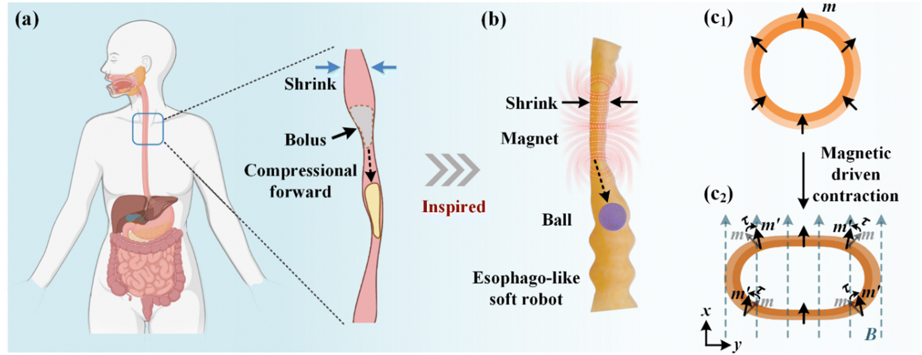 | ||
| Fig. 1 Magnetic esophagus-inspired soft robot (MESR) inspired by esophageal swallowing behavior. (a) The schematic diagram of the biological behavior of the esophagus to push food pellets forward through contraction and deformation. (b) The MESR contracted and pushed the ball under the action of an external magnetic field. (c) Magnetization and deformation process design of MESR. | ||
Inspired by the swallowing behavior involving esophageal contraction in animals, this study presents a magnetic esophagus-inspired soft robot (MESR) that can transport objects in an on-demand way. As depicted in Fig. 1b, the MESR featured a distinctive hollow corrugated tube structure, capable of undergoing deformation and transporting objects under the influence of an external magnetic field. The radial magnetization direction was designed as illustrated in Fig. 1c1. The driving magnetic field B was designed to be along the positive x-axis, as shown in Fig. 1c2. Under the influence of this driving magnetic field, the residual magnetization strength m in each part of the MSER would experience a magnetic torque τ, causing a positive deflection along the x-axis and consequently leading to MESR's contraction deformation in the x-axis direction. Upon removing the external magnetic field, the MESR could return to its initial state under the action of internal elastic forces. The combination of this magnetic-driven deformation capability with the design of the hollow corrugated tube structure endows MESR with excellent material transport capabilities. MESR could transport hydrogel balls in horizontal and vertical directions at transport speeds of 6.4 mm s−1 and 5.2 mm s−1, respectively. In addition, the MESR can also continuously transport multiple objects of different shapes and transport solid or insoluble liquids underwater. Abaqus numerical simulations have been employed to unveil the magnetic-driven deformation mechanism of MESR. Furthermore, the abilities of the MESR to deform and transport objects were optimized by adjusting material and structural parameters. Based on the horizontal and vertical transport capability of MESR, a 3D-SEMR was designed, which can realize the on-demand transmission of objects in three-dimensional space. This work realized large-scale deformation and directional transport objects of magnetic control soft robots and further promoted the development of magnetic-driven soft robots.
Experimental
Preparation of the MESR
The MESR was prepared using a 3D printing mold-assisted method. First, a DLP 3D printer (the Anycubix Photon Mono M5S) printed molds with the hollow bellows structure. Then, the NdFeB magnetic powder (LW-N-400, purchased from Guangzhou Xinnord Transmission Components Co., Ltd, remanence of 787.5 mT, mesh number of 400 mesh, density of 7.57 g cm−3) and Ecoflex liquid silicone (model: T605 A&B, purchased from Shenzhen Hongyejie Technology Co., Ltd, Viscosity 2000 cps, density 1.05 g cm−3) were stirred by a mechanical mixer at a speed of 1500 rpm for 5 minutes in a specific ratio to obtain NdFeB/Ecoflex mixed magnetic liquid. The magnetic liquid was then placed in a vacuum drying oven (GHZ-6020, Celaine Il Precision Control Wet Equipment Co., Ltd) at room temperature and vacuumed for half an hour to remove the air inside. Then the magnetic liquid was injected into the mold, the mold was rotated so that it was evenly covered on the inner surface of the mold, and then it was placed in the oven at 50 °C for 30 minutes to cure, and a layer of corrugated tube structure film could be obtained on the inner wall of the mold. After repeating the film-forming process at different times, hollow bellows with different thicknesses were obtained. Then the obtained bellows structure hose was folded horizontally and magnetized with a magnetizing machine (MA-2030, Shenzhen Jiuzhu Company, magnetizing voltage 1900 V) to obtain a MESR with special magnetic pole distribution.Characterization analysis
All optical images were taken with a SONY camera (a6300 SONY). Scanning microscopic photographs of magnetic polymers were obtained by environmental scanning electron microscopy (ESEM, Quanta 200, FEI, Netherlands). XRD patterns were obtained using an X-ray diffractometer (XRD, X’Pert3 Powder Panaco, Netherlands). Infrared thermal imaging images were taken with an infrared camera (Ti401 PRO, Fluke Company, USA). The mechanical parameters of the NdFeB/Ecoflex composite were determined using an electronic dynamic and static fatigue testing machine (E1000, ITW Group Interstrand GMBH).Experiments on transporting objects by the MESR
The MESR was fixed horizontally or vertically on the acrylic plate, and a hydrogel ball that was fully swollen in warm water at 60 °C was inserted into it, and then the magnet (20 × 20 × 20 mm) was manipulated by a machine hand to move along a specific trajectory to achieve the directional transport of MESR.Numerical simulation
Ansys Maxwell software was used to analyze the surface magnetic field distribution form of MESR. The equivalent magnetic characteristics of the magnetic complex with 60% magnetic powder mass fraction were set as follows: equivalent relative permeability 1, equivalent remanence 0.1075 T. The magnetic drive deformation process of MESR was simulated by Abaqus numerical simulation software. The direction of the magnetic field was square along the x-axis. Please refer to Note S1 in the ESI† for details.Results and discussion
The preparation of the MESR
The MESR with a hollow corrugated tube structure was produced through a series of steps involving the uniform mixture of Ecoflex liquid silicone and NdFeB magnetic powders, followed by multiple curing and magnetization folding processes. The detailed preparation procedure is illustrated in Fig. 2. | ||
| Fig. 2 Preparation process of the MESR. (a) and (b) The mold with a hollow bellows structure was obtained by DLP 3D printing. (c) The NdFeB/Ecoflex magnetic liquid mixture was injected through a hole above the mold. (d) The magnetic mixture liquid was evenly covered on the inner surface of the mold by rotating the mold. (e) and (f) Stand curing release to obtain magnetic hose. (g) and (h) Folding magnetization to obtain MESR with N–S pole distribution. | ||
The process of multiple curing into films is depicted in Fig. 2a–f. Specifically, the first step involves the preparation of a rectangular mold using a 3D printer, as shown in Fig. 2a and b. The mold has dimensions of 26 mm in length, 26 mm in width, and 104 mm in height, featuring periodic through-holes with a corrugated tube structure. The detailed geometric profile of the mold is illustrated in Fig. S1 (ESI†). Next, NdFeB powders and Ecoflex liquid silicone were uniformly mixed in a predetermined mass ratio to obtain a magnetic mixture. Subsequently, this mixture was placed in a vacuum-drying chamber to evacuate air from the interior. Then the film formation process was carried out on the inner wall of the cuboid mold. As shown in Fig. 2c and d, the through hole at the bottom of the mold was tightly sealed, and the previously removed air mixture was injected into the mold through the hole above the mold. The cuboid mold was then rotated so that the mixture was evenly coated on the inside surface of the mold. The excess mixture was then drained through the hole at the bottom of the mold. Finally, the cuboid mold with the NdFeB/Ecoflex mixture attached to the inner wall was placed at room temperature for 20 minutes and then dried in an oven at 50 °C for 30 minutes. A layer of bellows structure film could be obtained on the inner wall of the mold. By repeating this curing into the film process multiple times and demolding, magnetic soft tubes with hollow corrugated structures of different thicknesses could be obtained (Fig. 2e and f). Finally, the magnetic soft tubes with corrugated structures were fully compressed and folded along the horizontal direction. They were then magnetized using a magnetizing machine to obtain the MSER with a special magnetic pole distribution.
The morphology and structural characterization of the MESR
As shown in Fig. 3a, the MESR prepared by the preparation process shown in Fig. 2 after six times of curing film forming process is 18.0 mm in maximum diameter, 15.3 mm in minimum diameter, and 0.8 mm in thickness. Its surface includes eight segments of periodic corrugations, and the interior consists of seven segments of periodic chambers, showcasing excellent self-supporting capability.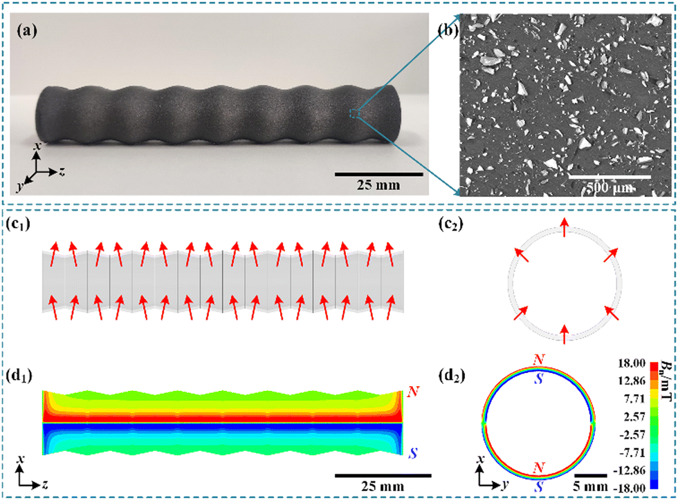 | ||
| Fig. 3 Morphology, structure and magnetic distribution of the MESR. (a) Optical photograph of the MESR. (b) ESME diagram of cross-section of the MESR. (c) and (d) Magnetic field distribution of the MESR. | ||
The stable and uniform distribution of NdFeB magnetic powder in the Ecoflex silicone matrix is crucial for the MESR to generate a controllable magnetic field distribution. Microscopic morphology of the MESR cross-section was observed using environmental scanning electron microscopy (ESME). As shown in Fig. 3b, revealing a relatively uniform distribution of NdFeB magnetic powder within the composite material system. X-ray diffraction spectra in Fig. S2 (ESI†) indicate the stable presence of both the dispersed phase (NdFeB magnetic powder) and matrix phase (Ecoflex silicon) in the mixture. Utilizing the Ansys Maxwell numerical simulation software, the magnetic field distribution of MESR was analyzed. The magnetization directions of MESR components are illustrated in Fig. 3c1 and c2. The numerical simulation results of the surface magnetic field distribution in MESR's front view and left view are shown in Fig. 3d1 and d2, respectively. It is important to note that the figures present the normal component Bn of the magnetic field. At a location where Bn is greater than 0 mT, it indicates that magnetic field lines depart from the robot's surface, representing the N pole. On the other hand, Bn less than 0 mT signifies that magnetic field lines enter the interior of the robot, representing the S pole. It can be observed that the inner and outer walls of the fabricated MESR are distributed with alternating N–S magnetic poles.
Magnetic drive deformation process of MESR
The deformation ability of existing magnetic-driven soft robots is mainly embodied in bending, torsion, expansion, etc., and rarely can shrink and deform, which restricts the ability of the magnetic-driven soft robot to continuously transport objects. The magnetic pole distribution of the robot determines the direction of the magnetic torque under the action of the external magnetic field and then affects the form of its magnetic-driven deformation. As shown in Fig. 4, magnetic fields with a size of 80 mT were applied to different positions at the bottom of the MESR through magnetic blocks, and the corresponding parts of the MESR of the hollow bellows structure with N–S magnetic pole distribution on the surface could all shrink and deform. In addition, the soft robot has excellent elasticity, with Young's modulus of 3.07 MPa (Fig. S3, ESI†). After removing the external magnetic field excitation, the deformed part of the soft robot will overcome gravity and the attraction of the upper and lower walls under the action of its own elasticity and return to its original shape. The MESR with an external diameter of 18 mm could shrink and deform to a minimum height of about 2 mm under the drive of a magnetic field, showing excellent shrinkage and deformation ability. In addition to shrinkage deformation, driven by the external magnetic field, MESR can also achieve complex movements such as tumbling, rotation, and folding, which greatly expands the working range of MESR (shown in Movie S1, ESI†).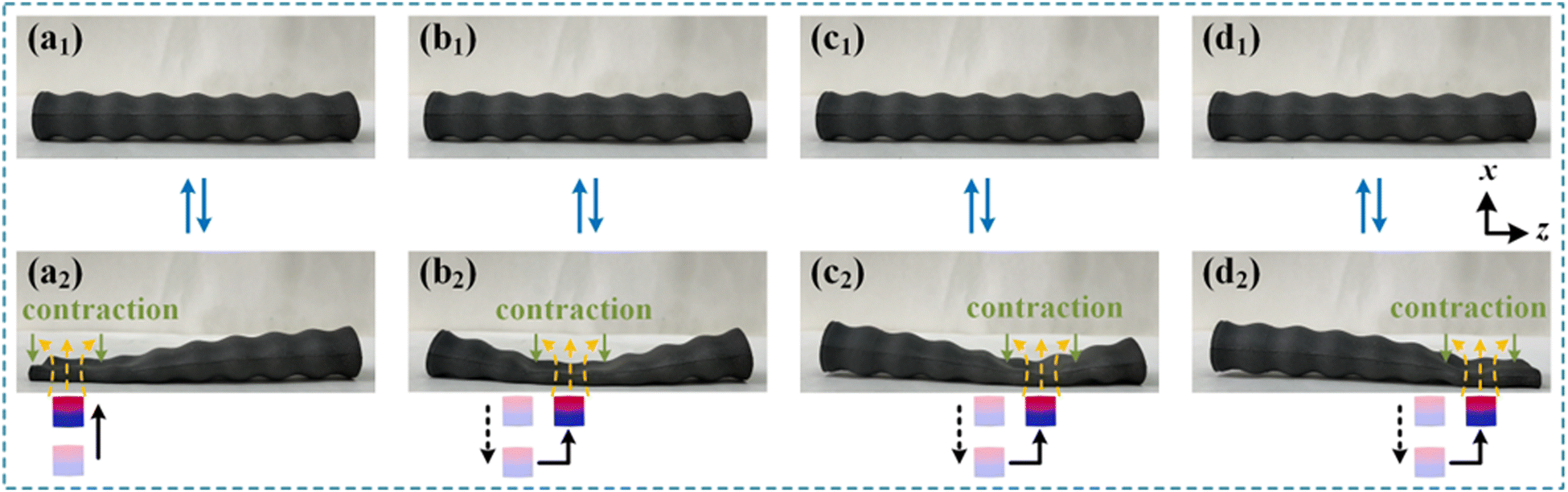 | ||
| Fig. 4 Under the action of the external magnetic field, the various parts of the MESR would periodically shrink. (a1)–(d1) Initial state. (a2)–(d2) Contractile states of different parts of MESR. | ||
Mechanism explanation of deformation ability of the MESR magnetic drive
Under the action of an external magnetic field, the magnetic moment inside the fully magnetized NdFeB/Ecoflex magnetic soft composite would be shifted to the direction of the external magnetic field under the action of the magnetic moment. Due to the mechanical limitation of the polymer matrix, the magnetic moment would cause local stress inside the macroscopic deformation of the material. Therefore, when the magnetic field in the positive direction of the x-axis was applied, all parts of the MESR were magnetized in the direction of the x-axis. The magnitude of the applied magnetic field affected the magnitude of the magnetic moment of the material and then affected the magnetic driving deformation ability of the MESR.Abaqus software was used to simulate and study the deformation mechanism of MESR under the action of an external magnetic field. The magnetic and mechanical parameters of NdFeB/Ecoflex magnetic response soft composite materials with different magnetic powder content used in numerical simulation are shown in Table S1 (ESI†). The remanent magnetic direction of each part of the MESR used is shown in Fig. 3c1–c2. In addition, due to the deformation under the action of the magnetic field, the magnetic-driven deformation of the first chamber of MESR was used for numerical simulation.
Fig. 5 shows the maximum actual principal strain distribution and displacement distribution of the bionic esophageal robot with NdFeB content of 60 wt% and thickness of 0.8 mm driven by magnetic fields of different sizes, and the direction of the driven magnetic field is positive along the x-axis. As illustrated in Fig. 5a1–f1, with the enhancement of the magnetic torque caused by the increase of the magnetic field, the local maximum principal strain (LEmax) in the robot structure gradually increased. As a result, the macroscopic displacement (Ux) of the robot gradually increased (Fig. 5a2–f2), and the contraction and deformation ability of the MESR was gradually enhanced. In addition, Fig. 5a1–f1 shows the significance of flexible NdFeB/Ecoflex composites for the continuous deformation of the robot. The evenly distributed maximum principal strain enabled the robot to avoid the destruction of the material structure due to excessive concentrated stress. It should be noted that when the external magnetic field was greater than 80 mT, as illustrated in Fig. 5e2–f2, additional enhancement of the driving magnetic field exhibits minimal effect on improving the shrinkage and deformation ability of MESR. Compared with the 80 mT magnetic field, the maximum displacement of the second chamber caused by the 100 mT magnetic field was only 7.6% larger.
 | ||
| Fig. 5 Numerical simulation analysis of magnetic-driven deformation mechanism of MESR. (a1)–(f1) Relationship between the maximum actual principal strain of MESR and the magnitude of the applied magnetic field. (a2)–(f2) Relation between MESR displacement and applied magnetic field. | ||
The ability of MESR to transport objects horizontally
Fig. 6b shows the front view of the process of MESR transporting elastic hydrogel balls in the horizontal direction (x-axis direction). At the initial moment, the elastic hydrogel ball was placed in the second chamber inside the MESR (Fig. 6b1). The contraction of the first chamber of the robot was controlled by an external magnet, and the hydrogel ball was transported to the third chamber of the robot (Fig. 6b2). Fig. 6a is the schematic diagram of the transport process of the elastic hydrogel ball, which more clearly shows the control process of the external magnet. The process of MESR transporting the hydrogel ball from one chamber inside it to the next chamber can be broken down into the following two steps: Initially, the magnet was gradually moved close to the precious chamber of the hydrogel ball to induce contraction. During this phase, the hydrogel ball experienced extrusion pressure, propelling it forward into the next chamber. The magnetic block was then slowly moved downward away from the MESR to restore it to its initial state. It is worth noting that owing to the distinctive bellows structure design of MESR, during the MESR's recovery state in the aforementioned second step, the hydrogel ball successfully transported to the next chamber can remain stably stationary within it. In other words, the hydrogel ball will not migrate to other chambers due to the external force, thereby ensuring the overall stability of the hydrogel ball transportation process. After repeating the above transport process six times, the designed MESR can transport the hydrogel ball from one end to the other in a horizontal direction, with an average transport speed of about 6.4 mm s−1. | ||
| Fig. 6 Experiment study on horizontal transport capacity of MESR. (a1)–(a7) Diagram of the process of transporting hydrogel ball. (b2)–(b7) Optical photograph of the process of transporting hydrogel ball. (c1)–(c7) Infrared thermal image of the process of transporting hydrogel ball. | ||
To more clearly show the forward trajectory of the hydrogel ball in an opaque MESR, an infrared thermal imager was used to photograph the transport process of the hydrogel ball from an overhead angle. The initial temperature of the hydrogel ball was about 60 °C, and the temperature of the test environment was about 15 °C. In the transport process of the hydrogel ball, the high temperature of the hydrogel ball would gradually transfer heat to the low temperature of the MESR, so that its surface temperature would gradually increase. As shown in Fig. 6c, whenever the hydrogel ball moved into a chamber inside the MESR, a temperature increase could be observed in the infrared thermal image of the corresponding region on the MESR surface. This is because the overall temperature of the hydrogel ball was higher than the ambient temperature. As the hydrogel ball were transported by the MESR, it would continue to release heat to the environment, so the overall surface temperature of the MESR would gradually increase along the x-axis.
In addition to transporting spherical objects, the MESR can also transport objects of other shapes (Movie S2 shows its process of transporting square objects, ESI†). Further, as shown in Movie S3 and S4 (ESI†), the MESR also can transport objects continuously. Further, the MESR can work underwater, enabling solid hydrogel spheres (Movie S5, ESI†) and directional transport of liquid metals (Movie S6, ESI†). This indicates that MESR has a strong ability to transport objects.
The function of MESR in transporting objects vertically
In addition to the basic horizontal material transport, the MESR is also capable of transporting objects in the vertical direction against gravity driven by an external magnetic field. Fig. 7b shows the front view of the hydrogel sphere transport process of the MESR against gravity (gravity direction is negative y-axis direction). At the initial moment, the hydrogel ball was placed in the second chamber at the bottom of the robot (Fig. 7b1). At this time, the contraction of the first chamber at the bottom of the robot controlled by an external magnet could transport the hydrogel ball to the third chamber at the bottom of the robot (Fig. 7b2). Fig. 7a shows the transport process of the hydrogel ball. Similarly, the anti-gravity progression of the hydrogel ball in the MESR unfolds through two distinct steps: Initially, the magnetic block was slowly maneuvered towards the chamber below the hydrogel bead to contract it, which caused the hydrogel ball to be squeezed upward to the upper chamber. Subsequently, the magnetic block was then gradually moved backward away from the MESR, causing the MESR to revert to its initial state. | ||
| Fig. 7 Experimental study on vertical anti-gravity transport capacity of the MESR. (a1)–(a7) Schematic diagram of the process of transporting hydrogel ball. (b1)–(b7) Optical photograph of transporting hydrogel ball. (c1)–(c7) Infrared thermal image of transporting hydrogel ball. | ||
It is worth noting that when the MESR was in the recovery state, the distinctive bellows structure ensured that the hydrogel ball, having been conveyed to the upper chamber, received ample support from the chamber itself. This support effectively counteracts the force of gravity, mitigating the risk of the hydrogel ball descending back to the initial chamber. This feature serves as a crucial foundation for MESR's capability. After implementing the above transport process 6 consecutive times, the soft robot was able to transport the hydrogel ball from the bottom of the robot to the top in the positive direction of the y-axis at a transport speed of 5.2 mm s−1. The infrared thermal image corresponding to the anti-gravity transport process is shown in Fig. 7c (the test conditions are the same as those in Fig. 6c). It could be observed that as the hydrogel sphere moved upward in the interior of the MESR, the temperature of the corresponding area on the surface of the MESR also gradually increased, showing the advancing trajectory of the hydrogel sphere in the opaque MESR.
Optimization of transport capacity of the MESR
Under the same external magnetic field, the material transport ability of the MESR mainly depends on the design of its material and structural parameters. To quantitatively analyze the influence of different parameters of the MESR on its transport capacity, the successful transportation ratio (STR) of the MESR was defined, as shown in formula (1): | (1) |
Unless otherwise specified, the bellows structure has a MESR particle content of 60 wt%, an outer diameter of 18.0 mm, an inner diameter of 15.3 mm, and a thickness of 0.8 mm. The surface comprises 8 periodic corrugated segments and the interior contains 7 periodic chambers.
The wave depth of the MESR is an important factor affecting its material transport capacity. To quantitatively measure the ground ripple depth of the MESR, its wave depth coefficient Df is defined as shown in formula (2):
 | (2) |
Fig. S4 (ESI†) shows the relationship between MESR material transport capacity and wave depth coefficient Df. With the increase of wave depth coefficient Df, the inner diameter of MESR gradually decreased, the radius of the hydrogel ball that can be transported gradually decreased, and the material transport capacity of MESR also decreased. For the vertical transport scenario, the mass transport capacity of MESR also decreased with the increase of Df. However, when the Df value is less than 0.15, MESR cannot provide enough support force to balance the gravity of the hydrogel ball because the ripple depth is too shallow. At this time, the hydrogel ball cannot be stably positioned within the corrugated chamber of the MESR; instead, it descends directly away from the MESR under the influence of gravity, resulting in the loss of the MESR's transport capability (represented by STR = 0 in Fig. S4, ESI†). In addition, it is worth noting that when the Df value is equal to 0.15, due to the need to overcome the effect of hydrogel ball gravity in the vertical anti-gravity transport scenario under the same magnetic field, the maximum radius of the hydrogel ball that the robot can transport in the vertical anti-gravity scenario is slightly smaller than that in the horizontal transport scenario. To ensure that the MESR has a good material transport capability in both horizontal and vertical anti-gravity scenarios, the Df of MESR used in the subsequent research is 0.15.
In addition to the wave depth, the magnetic particle content of the MESR also affects its transport capacity. Fig. S5a (ESI†) shows the relationship between the transport capacity of the MESR and its magnetic particle content. It can be seen that when the mass fraction of NdFeB magnetic powder was 60 wt%, the MESR exhibited the best transport capacity under both horizontal and vertical transport scenarios, with STR values of 0.82 and 0.78, respectively. This is mainly because under the same magnetic field, the MESR with a magnetic powder content of 60 wt% has the best deformation capacity, which can provide the maximum extrusion pressure to drive the hydrogel ball forward. Numerical simulation analysis further revealed the reason. Fig. S5b (ESI†) shows the displacement changes of the MESR with different magnetic particle content under the action of 80 mT external magnetic fields calculated by Abaqus numerical simulation software. It can be seen that the MESR with a magnetic particle content of 60 wt% shows the best magnetic driven shrinkage deformation ability. Compared with the MESR with magnetic particle contents of 40 wt%, 50 wt%, and 70 wt%, the maximum displacement of the second chamber of the robot with a magnetic particle content of 60 wt% was increased by 10.4%, 8.0%, and 16.6%, respectively.
The influence of thickness d of the MESR on its transport capacity was further explored. As shown in Fig. S5c (ESI†), with thickness d increasing from 0.8 mm to 1.0 mm, the horizontal and vertical transport capacity STR decreased from 0.82 and 0.78 to 0.78 and 0.76, respectively. This phenomenon arises from the inverse relationship between the thickness of the robot and its capacity to contract and deform under the influence of the magnetic field. With an increase in thickness, the robot's ability to undergo shrinkage and deformation gradually diminishes, subsequently leading to a gradual reduction in the extrusion driving force available to support the hydrogel beads. When the thickness d increased to 1.2 mm, the small magnetic drive deformation ability made it impossible for the robot to drive the hydrogel beads upward against gravity. When the thickness d of MESR increased to 1.4 mm, the further reduced shrinkage deformation ability made it lose the ability to drive the hydrogel balls forward in both horizontal and vertical anti-gravity scenarios. In addition, when the thickness d of was reduced to 0.6 mm, the small elastic properties after the removal of the applied magnetic field made it difficult to overcome the large magnetic attraction between the N–S magnetic poles on the upper and lower surfaces and return to the initial state, and no longer have material transport capability. Similarly, Abaqus numerical simulation also analyzed the influence of thickness on the deformation ability of MESR magnetic drive. The magnetic-driven shrinkage deformation ability of MESR decreased significantly with the increase of its thickness (as shown in Fig. S5d, ESI†). Compared with MESR with thicknesses of 1.4 mm, 1.2 mm, and 1.0 mm, the maximum displacement of 0.8 mm MESR in the second chamber increases by about 32.3%, 20.4%, and 9.8%, respectively.
Among the three influencing factors “thickness”, “magnetic particle content” and “wave depth coefficient”, the thickness and wave depth coefficient determine the maximum deformation rate of the MESR, while the magnetic particle content determines the driving force of the MESR. Therefore, under the condition of optimal magnetic particle content (60 wt%, shown in Fig. S5a, ESI†), orthogonal experiments were used to study the combined effects of thickness and wave depth coefficient on the transport capacity of MESR. As shown in Fig. S6 (ESI†), when the wave depth coefficient is 0 and the thickness is 0.8 mm, STR(H) is the largest, that is, the MSER has the strongest horizontal transport capacity. When the wave depth coefficient is 0.10 and the thickness is 0.8 mm, STR(V) is the largest, that is, the vertical anti-gravity transport capacity of the MESR is the largest.
In addition to STR, the size range of objects that the MESR can transport is also an important indicator of its transport capacity. The transportation success rate of hydrogel spheres with different diameters was studied through experiments, as shown in Fig. S7 (ESI†). It can be seen that the diameter range of the hydrogel spheres successfully transported by MESR in the horizontal direction is 10–18 mm, and the diameter range of hydrogel spheres successfully transported in the vertical anti-gravity direction is 13–18 mm. Another indicator of the MESR transport capacity is the transport speed, which can be improved by increasing the magnitude and the changing speed of the external magnetic field.
On-demand transport capacity of the MESR in three-dimensional space
To further expand the transport capability of the MESR and enable it to transport hydrogel balls along on-demand paths in three-dimensional space, a three-dimensional magnetic esophagus-inspired soft robot (3D-MESR) with a cross bellows structure was prepared based on the bellows structure of the above soft robot in this section.Firstly, a mold containing a hollow structure of cross bellows was prepared using a DLP 3D printer (as shown in Fig. S8, ESI†). Then the 3D-MESR was obtained by the multiple pouring method (Fig. 8b1). 3The D-MESR combines the horizontal and anti-gravity vertical transport capabilities shown above with the ability to transport objects at a fixed point along a specific path in three-dimensional space. Driven by a magnetic field, the 3D-MESR can transport hydrogel balls from the bottom of the robot to the right end of the robot. The optical photo of the transportation process taken from the front view is shown in Fig. 8b. At the initial moment, the hydrogel ball was placed in the second chamber at the bottom of the 3D-MESR (Fig. 8b1). Through the application of an external magnetic field, the 3D-MESR successfully extruded the hydrogel ball from the chamber at the end of the upper right arm within 28 s (Fig. 8b7). The transport process includes both anti-gravity transport and horizontal transport. The schematic diagram of the whole process is shown in Fig. 8a. The hydrogel ball can be stably seated in each chamber of the robot. The infrared thermal image shown in Fig. 8c clearly shows the movement trajectory of the hydrogel ball inside the 3D-MESR during the transport process. In addition to being able to follow these two paths, the 3D-MESR can also transport hydrogel balls along all the other paths and even control the movement of the hydrogel spheres in the direction of gravity (as shown in Movie S7, ESI†).
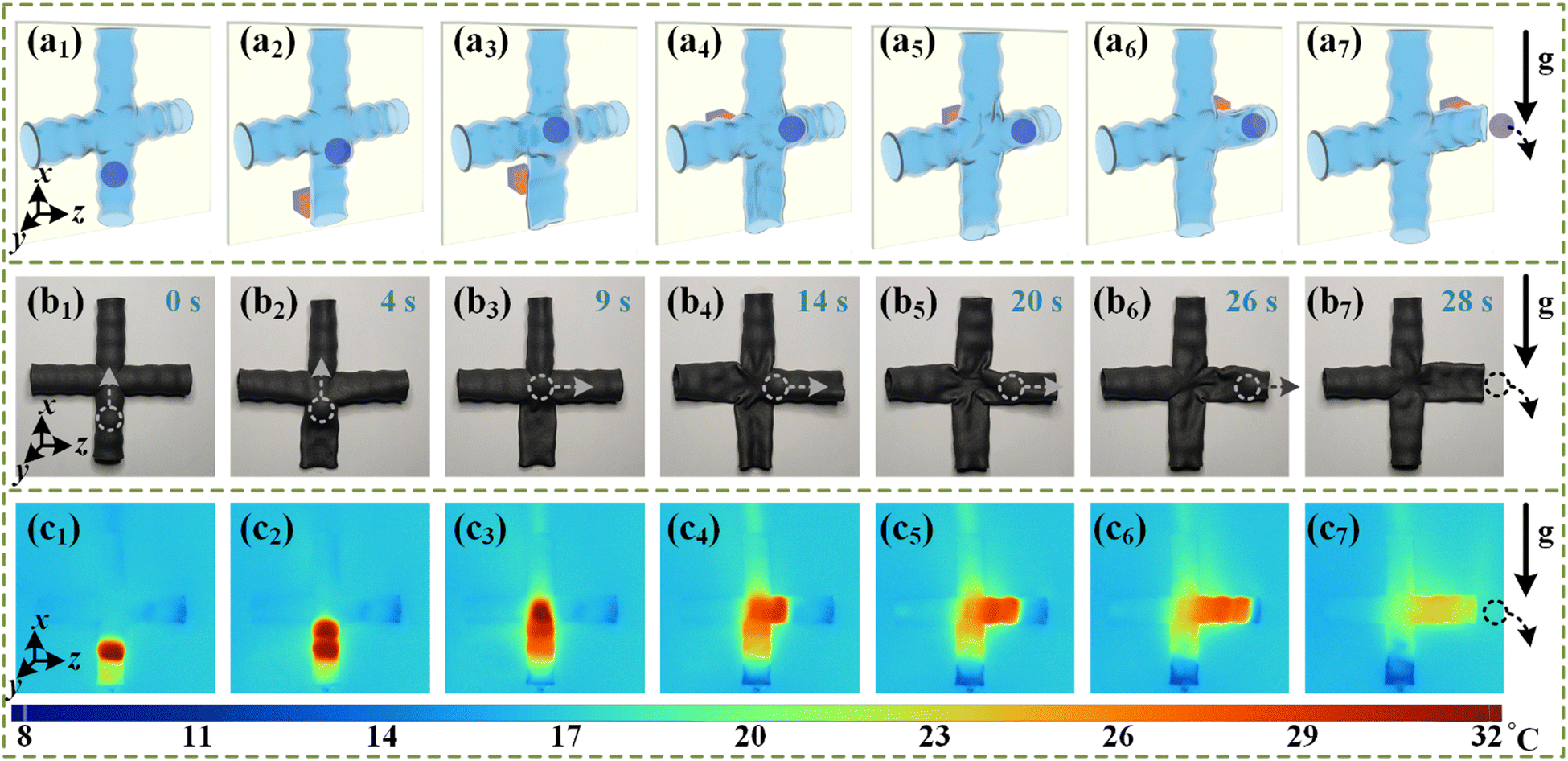 | ||
| Fig. 8 Experimental study on directional transport capability of MESR in complex paths. (a1)–(a7) Schematic diagram of the process of directional transporting hydrogel spheres. (b1)–(b7) Optical photograph of directional transporting hydrogel ball. (c1)–(c7) Infrared thermal image of directional transporting hydrogel ball. | ||
Conclusions
Based on a NdFeB/Ecoflex magnetic-soft composite material, a bellows structure magnetic soft robot MESR inspired by the esophagus was designed in this work, which has a superior 3D spatial orientation transport capability. The surface of the MESR exhibits a distinctive N–S type magnetic pole distribution, endowing it with excellent deformability under the influence of the magnetic field. The Abaqus numerical simulation elucidated the mechanism behind the magnetic-driven deformation of the MESR. Furthermore, a detailed analysis was conducted on how the magnetic particle content and thickness of the MESR impact the mitigation of deformation in the MESR. This analysis serves as guidance for the optimization of MESR's functionality. This magnetic drive deformation ability combined with the hollow bellows structure design endowed the MESR with excellent material transport capability. With an outer diameter of 18 mm, the MESR could stably transport hydrogel balls with a diameter of 14.2 mm and a weight of 1.5 g in horizontal and vertical anti-gravity scenarios. The speeds were 6.4 mm s−1 and 5.2 mm s−1 respectively. Furthermore, the MESR could continuously directionally transport objects of various shapes in air or underwater environments. In addition, it can also be used to transport insoluble liquids underwater. The material transport capacity of the MESR was optimized by adjusting the magnetic particle content, wave depth coefficient, and thickness. Combined with the horizontal and vertical anti-gravity transport capability of magnetic bellows MESR, a 3D-MESR with cross bellows was designed, which could stably transport elastic hydrogel balls along an on-demand path driven by a magnetic field. In this study, the innovative design of magnetic-driven bellows demonstrates excellent shrinkage and deformation capabilities. The MESR can realize untethered motion control through the external magnetic field and can carry out directional transport of objects in complex and narrow underwater environments, which is of great significance in the practical application of the directional delivery of drugs and environmental exploration.Author contributions
Shanfei Zhang: conceptualization, data curation, methodology, formal analysis, investigation, and writing – original draft, Qi Wang: methodology, software, validation, and writing – review & editing; Zhuofan Li: methodology, formal analysis, and data curation; Jingyuan Zhang: methodology, formal analysis, and data curation; Yizhuo Xu: conceptualization, methodology, formal analysis, data curation, investigation, writing – original draft, and writing – review & editing; Bin Su: conceptualization, methodology, writing – original draft, writing – review & editing, and supervision.Data availability
The data supporting this article have been included as part of the ESI.†Conflicts of interest
There are no conflicts to declare.Acknowledgements
This work was supported by the National Natural Science Foundation of China (52375336) and Interdisciplinary Research Program of Hust (2023JCYJ011).Notes and references
- M. A. Haq, Y. Su and D. Wang, Mater. Sci. Eng., C, 2017, 70, 842–855 CrossRef.
- S. D. Cezan, H. T. Baytekin and B. Baytekin, Soft Robot., 2020, 7, 444–450 CrossRef.
- Y. Kim, G. A. Parada, S. Liu and X. Zhao, Sci. Robot., 2019, 4, eaax7329 CrossRef.
- R. Tao, L. Ji, Y. Li, Z. Wan, W. Hu, W. Wu, B. Liao, L. Ma and D. Fang, Composites, Part B, 2020, 201, 108344 CrossRef CAS.
- Q. Shen, S. Trabia, T. Stalbaum, V. Palmre, K. Kim and I.-K. Oh, Sci. Rep., 2016, 6, 24462 CrossRef CAS PubMed.
- Y.-Y. Xiao, Z.-C. Jiang, X. Tong and Y. Zhao, Adv. Mater., 2019, 31, 1903452 CrossRef.
- N. Wang, C. Cui, H. Guo, B. Chen and X. Zhang, Sci. China: Technol. Sci., 2018, 61, 1512–1527 CrossRef.
- J. Zhang, R. H. Soon, Z. Wei, W. Hu and M. Sitti, Adv. Sci., 2022, 9, 2203730 CrossRef CAS PubMed.
- Y. Hou, H. Wang, R. Fu, X. Wang, J. Yu, S. Zhang, Q. Huang, Y. Sun and T. Fukuda, Lab Chip, 2023, 23, 848–868 RSC.
- B. Yuan, C. Zhao, X. Sun and J. Liu, Adv. Funct. Mater., 2020, 30, 1910709 CrossRef CAS.
- A. A. Amiri Moghadam, K. Torabi, A. Kaynak, M. N. H. Zainal Alam, A. Kouzani and B. Mosadegh, Soft Robot., 2016, 3, 82–97 CrossRef.
- H. Cui, D. Yao, R. Hensleigh, H. Lu, A. Calderon, Z. Xu, S. Davaria, Z. Wang, P. Mercier, P. Tarazaga and X. Zheng, Science, 2022, 376, 1287–1293 CrossRef CAS PubMed.
- Z. Li, S. Zhang, Q. Wang, Y. Xu, Y. Li, X. Chen, P. Chen, D. Chen, Y. Shi and B. Su, Adv. Mater., 2024, 2409142 CrossRef CAS.
- G. Mao, D. Schiller, D. Danninger, B. Hailegnaw, F. Hartmann, T. Stockinger, M. Drack, N. Arnold and M. Kaltenbrunner, Nat. Commun., 2022, 13, 4456 CrossRef CAS PubMed.
- E. W. Hawkes, L. H. Blumenschein, J. D. Greer and A. M. Okamura, Sci. Robot., 2017, 2, eaan3028 CrossRef.
- S. W. Kwok, S. A. Morin, B. Mosadegh, J.-H. So, R. F. Shepherd, R. V. Martinez, B. Smith, F. C. Simeone, A. A. Stokes and G. M. Whitesides, Adv. Funct. Mater., 2014, 24, 2180–2187 CAS.
- L. Wang, Z. Meng, Y. Chen and Y. Zheng, Adv. Intell. Syst., 2021, 3, 2000267 Search PubMed.
- S. Zhang, Y. Xu, Z. Li, Y. Li, Z. Liu, X. Chen, P. Chen, M. Chen, P. Zhang, C. Cai, Q. Wang and B. Su, Adv. Funct. Mater., 2024, 2402563 CAS.
- M. Torbati, K. Mozaffari, L. Liu and P. Sharma, Rev. Mod. Phys., 2022, 94, 025003 Search PubMed.
- S. Won, H. E. Lee, Y. S. Cho, K. Yang, J. E. Park, S. J. Yang and J. J. Wie, Nat. Commun., 2022, 13, 6750 CAS.
- W. Hu, G. Z. Lum, M. Mastrangeli and M. Sitti, Nature, 2018, 554, 81–85 CAS.
- Z. Ren and M. Sitti, Nat. Protoc., 2024, 19, 441–486 CAS.
- Y. Kim and X. Zhao, Chem. Rev., 2022, 122, 5317–5364 CAS.
- X. Ke, H. Yong, F. Xu, H. Ding and Z. Wu, Nat. Commun., 2024, 15, 1491 CAS.
- H. Deng, K. Sattari, Y. Xie, P. Liao, Z. Yan and J. Lin, Nat. Commun., 2020, 11, 6325 CAS.
- X. Guo, W. Li, F. Fang, H. Chen, L. Zhao, X. Fang, Z. Yi, L. Shao, G. Meng and W. Zhang, Sci. Adv., 2024, 10, eadk3855 Search PubMed.
- D. Zhang, J. Zhang, Y. Jian, B. Wu, H. Yan, H. Lu, S. Wei, S. Wu, Q. Xue and T. Chen, Adv. Intell. Syst., 2021, 3, 2000208 CrossRef.
- Y. Lee, F. Koehler, T. Dillon, G. Loke, Y. Kim, J. Marion, M.-J. Antonini, I. C. Garwood, A. Sahasrabudhe, K. Nagao, X. Zhao, Y. Fink, E. T. Roche and P. Anikeeva, Adv. Mater., 2023, 35, 2301916 CAS.
- Y. Yue, Q. Wang, Z. Ma, Z. Wu, X. Zhang, D. Li, Y. Shi and B. Su, Soft Robot., 2022, 10, 66–76 CrossRef.
- J. Ye, Y.-C. Yao, J.-Y. Gao, S. Chen, P. Zhang, L. Sheng and J. Liu, Soft Robot., 2022, 9, 1098–1107 CrossRef PubMed.
- J. Hu, Z. Nie, M. Wang, Z. Liu, S. Huang and H. Yang, Angew. Chem., Int. Ed., 2023, 62, e202218227 CrossRef CAS.
- Q. Wang, Z. Wu, J. Huang, Z. Du, Y. Yue, D. Chen, D. Li and B. Su, Composites, Part B, 2021, 223, 109116 CrossRef.
- E. B. Joyee, A. Szmelter, D. Eddington and Y. Pan, Soft Robot., 2020, 9, 1–13 Search PubMed.
- F. J. Chen, S. Dirven, W. L. Xu, J. Bronlund, X. N. Li and A. Pullan, Mechatronics, 2012, 22, 556–567 CrossRef.
- N. H. May, K. W. Davidson, W. G. Pearson Jr and A. K. O’Rourke, Head Neck, 2020, 42, 467–475 CrossRef.
- T. Guillermo, L. Andrea, D. L. Juan, H. V. Xochitl, M. H. Billy and C. Todd, Microb. Ecol. Health Dis., 2015, 26, 25876 Search PubMed.
Footnotes |
| † Electronic supplementary information (ESI) available. See DOI: https://doi.org/10.1039/d4tc03075c |
| ‡ Shanfei Zhang and Qi Wang contributed equally to this work. |
| This journal is © The Royal Society of Chemistry 2025 |