
 Open Access Article
 This Open Access Article is licensed under a
 Creative Commons Attribution 3.0 Unported Licence
A meta-linked isomer of ITIC: influence of aggregation patterns on open-circuit voltage in organic solar cells†
Kai
Wang
a,
Seihou
Jinnai
 *ab,
Kaito
Uesaka
c,
Akira
Yamakata
*cde and
Yutaka
Ie
*ab
*ab,
Kaito
Uesaka
c,
Akira
Yamakata
*cde and
Yutaka
Ie
*ab
aThe Institute of Scientific and Industrial Research (SANKEN), The University of Osaka, 8-1 Mihogaoka, Ibaraki, Osaka 567-0047, Japan. E-mail: jinnai@sanken.osaka-u.ac.jp; yutakaie@sanken.osaka-u.ac.jp
bInnovative Catalysis Science Division, Institute for Open and Transdisciplinary Research Initiatives (ICS-OTRI), The University of Osaka, 2-1 Yamadaoka, Suita, Osaka, 565-0871, Japan
cGraduate School of Natural Science & Technology, Okayama University, 3-1-1 Tsushima-naka, Okayama 700-8530, Japan. E-mail: yamakata@okayama-u.ac.jp
dResearch Institute for Interdisciplinary Science, Okayama University, 3-1-1 Tsushima-naka, Okayama, 700-8530, Japan
eInstitute for Aqua Regeneration, Shinshu University, 4-17-1 Wakasato, Nagano-shi, Nagano 380-8553, Japan
First published on 25th April 2025
Abstract
Improving the open-circuit voltage (VOC) of organic solar cells (OSCs) remains an important challenge. While it is known that the energy levels at the donor/acceptor (D/A) interface affect the VOC, the impact of aggregation patterns on the energy levels at the D/A interface has not been fully elucidated. Herein, we focus on ITIC, a widely used acceptor in OSCs, and designed a meta-linked isomer of ITIC (referred to as im-ITIC) to alter molecular symmetry and modify substitution arrangements. Concentration-dependent 1H NMR spectra revealed that im-ITIC shows stronger aggregation behavior in solution. Single-crystal X-ray analysis showed that im-ITIC forms both tail-to-tail (J-aggregation) and face-to-face (H-aggregation) stacking modes, whereas ITIC exclusively forms tail-to-tail stacking. OSCs based on PBDB-T:im-ITIC showed a high VOC value of 1.02 V, which is 0.12 V higher than that of those based on PBDB-T:ITIC. Time-resolved infrared measurements revealed the lifetime of free electrons for the pristine and blend films. The energy levels of the charge transfer state (ECT) for PBDB-T:im-ITIC- and PBDB-T:ITIC OSCs were determined to be 1.57 and 1.39 eV, respectively, correlating with the VOC values. Theoretical calculations indicated that pronounced H-aggregation in im-ITIC increases the ECT compared with J-aggregation, contributing to the improved VOC. This study underscores the critical impact of molecular aggregation patterns on energy alignment and VOC enhancement, offering insights into molecular design for achieving high VOC in OSCs.
Introduction
Organic solar cells (OSCs) have garnered increasing attention owing to their advantages, including cost-effectiveness, lightweight nature, flexibility, suitability for large-scale manufacturing, and wavelength-selective applications.1–5 Significant progress in material design and device optimization has increased the power conversion efficiency (PCE) of single-junction OSCs up to 20%.6–9 The photovoltaic performance of OSCs is determined by three key parameters: short-circuit current density (JSC), the fill factor (FF), and open-circuit voltage (VOC). Recent advancements, particularly in state-of-the-art fused-ring acceptors, have enabled JSC and the FF to reach 85% of the Shockley–Queisser limit.10,11 However, achieving high VOC remains the primary challenge in the pursuit of high performance OSCs.The VOC of OSCs is primarily correlated with the energy level of the charge-transfer state (ECT), where a hole resides in the donor (D) phase and an electron in the acceptor (A) phase at the D/A interface (Fig. 1a).12,13 The ECT is largely influenced by the energy offset between the highest occupied molecular orbital (HOMO) of the donor and the lowest unoccupied molecular orbital (LUMO) of the acceptor at the D/A interface.14 While controlling the energy levels at the D/A interface is crucial for improving the VOC, the complexity and variability of the morphologies at the D/A interface make it challenging to develop strategies for controlling the ECT through molecular design.
 | ||
| Fig. 1 (a) Schematics for the CT state at the D/A interface and (b) chemical structures of im-ITIC and ITIC. | ||
The energy levels of organic semiconductors are affected by aggregation in the solid state and at the D/A interface.15 In dimer models, it is well-known that these energy levels vary depending on the aggregation mode, such as J- and H-aggregation.16–19 To investigate the influence of the aggregation patterns on the ECT and VOC, a W-shaped ITIC isomer, i.e.im-ITIC, was designed (Fig. 1b). ITIC is a representative acceptor in OSCs and belongs to C2h symmetry, where bulky substituents are introduced on both sides of the fused polycyclic π-conjugated chain.20 In contrast, im-ITIC exhibits C2v symmetry, with bulky substituents on one side of the conjugated chain. As a result, the intermolecular interactions between ITIC and im-ITIC are expected to differ, leading to distinct stacking conformations in the solid state. In this study, we aimed to elucidate the influence of the molecular structures of ITIC and im-ITIC on their aggregation patterns and to investigate the relationship among the aggregation, ECT at the D/A interface, and VOC of OSCs.
Results and discussion
Synthesis and characterization
The synthetic route to im-ITIC is shown in Scheme 1. Compound 1 was prepared following a previously reported method.21 Then, a Stille coupling reaction was carried out to give compound 2. im-IDTT was synthesized via nucleophilic addition of the aryllithium and a cyclization reaction using H2SO4/AcOH. The formylation of im-IDTT afforded im-IDTT-CHO, which was then subjected to Knoevenagel condensation with 1-(dicyanomethylene)-3-indanone to give im-ITIC. The synthetic details, structural characterization, 1H and 13C NMR spectra, and high-resolution mass spectrometry data are provided in the (ESI†). As shown in Fig. S1,† thermogravimetric analysis (TGA) showed that im-ITIC exhibits good thermal stability with a decomposition temperature of 342 °C at a 5% weight loss. | ||
| Scheme 1 Synthetic route to im-ITIC. | ||
The concentration-dependent 1H NMR spectra of im-ITIC in deuterated chloroform (CDCl3) solution were measured to investigate the aggregation behavior. As shown in Fig. 2 and S2,† certain protons in the aromatic region shift significantly with increasing concentration. Notably, the protons in the central ring (Ha), the thiophene ring (Hc), and the vinyl group (Hd), located on the side opposite to alkyl groups, shift to a higher field. In contrast, the shifts of the Hb protons, which are on the same side as the alkyl groups, are less pronounced. This result indicates that im-ITIC exhibits aggregation behavior on the side opposite to bulky substituents, which differs markedly from the J-aggregation pattern typically seen in ITIC (see Fig. S3† and other representative NFAs).
 | ||
| Fig. 2 Concentration-dependent 1H NMR spectra of the aromatic region for im-ITIC in CDCl3 at 20 °C. The entire spectra are given in Fig. S2.† | ||
Theoretical investigation
To gain insight into the effect of isomeric structure on electronic states, density functional theory (DFT) calculations were performed using Gaussian 16 software at the B3LYP/6-31G(d,p) level. As shown in Fig. S4,† the conjugated backbone of im-ITIC showed a planar configuration, similar to that of ITIC. Additionally, im-ITIC exhibits a significantly larger dipole moment (μ) of 12.14 D compared with 0.04 D for ITIC due to the C2v symmetry of its backbone. The distributions of the HOMO and the LUMO, along with their energy levels, are summarized in Fig. S5.† Both im-ITIC and ITIC exhibit similar frontier molecular orbital distributions, with im-ITIC featuring a deeper HOMO energy level of −5.57 eV, compared with −5.46 eV for ITIC. The LUMO energy level of im-ITIC shifts upward to −3.24 eV compared with −3.35 eV for ITIC.Electrochemical and photophysical properties
The electrochemical properties of im-ITIC and ITIC were investigated using differential pulse voltammetry (DPV) in o-dichlorobenzene/acetonitrile (CH3CN) (5/1) solutions containing 0.1 M tetrabutylammonium hexafluorophosphate (TBAPF6) as a supporting electrolyte. The potentials were calibrated by a ferrocene/ferrocenium (Fc/Fc+) redox couple as an internal standard. As shown in Fig. S6,† these isomers exhibited two reduction and oxidation peaks in cathodic and anodic sweeps, respectively. The first reduction potential (Ered) of im-ITIC was 0.07 V more negative than that of ITIC, while the first oxidation potential (Eox) was 0.11 V more positive. Based on the redox potentials, the LUMO energy level (ELUMO) and HOMO energy level (EHOMO) of im-ITIC and ITIC were determined to be −5.65/−3.79 and −5.54/−3.86 eV, respectively. These potentials of im-ITIC and ITIC are summarized in Table 1. The relative energy levels of im-ITIC and ITIC based on the DPV were qualitatively consistent with the DFT results shown in Fig. S5.†| Compounds | λ solmax (nm) | λ filmmax (nm) | λ filmonset (nm) | E optg (eV) | E HOMO (eV) | E LUMO (eV) | IE d(eV) | EA e(eV) |
|---|---|---|---|---|---|---|---|---|
| a In chloroform. b E optg was calculated using 1240/λfilmonset. c Determined via DPV in o-DCB/CH3CN containing 0.1 M of TBAPF6. d Estimated using PYS. e Estimated using LEIPS. | ||||||||
| im-ITIC | 621 | 636 | 704 | 1.76 | −5.65 | −3.79 | 5.97 | 3.85 |
| ITIC | 679 | 697 | 765 | 1.62 | −5.54 | −3.86 | 5.88 | 3.87 |
The UV-vis absorption spectra in chloroform solutions are shown in Fig. 3aim-ITIC showed a blue-shifted absorption band compared with ITIC, and their absorption maxima (λsolmax) were at 621 and 679 nm, respectively. The molar absorption coefficient (εsol) for im-ITIC (1.62 × 10⁵ L mol−1 cm−1) is almost comparable to that of ITIC (1.76 × 10⁵ L mol−1 cm−1), which is consistent with their oscillator strength in the DFT results (Fig. S5†). In the film state, the maximum absorption peaks (λfilmmax) of im-ITIC and ITIC are located at 636 and 699 nm. Based on the onset wavelength of the absorption spectra, the optical energy gaps (Eoptg) for im-ITIC and ITIC were estimated to be 1.76 and 1.62 eV, respectively.
 | ||
| Fig. 3 (a) UV-vis absorption spectra, (b) LEIPS, and (c) PYS of im-ITIC, ITIC in pristine films. (d) Energy level diagram of im-ITIC (blue), ITIC (green), and PBDB-T (black). | ||
To investigate the electron affinity (EA) and ionization energy (IE) of im-ITIC and ITIC, low-energy inverse photoemission spectroscopy (LEIPS)22,23 and photoelectron yield spectroscopy (PYS)24 were conducted. As shown in Fig. 3b and c, the IE/EA values for im-ITIC and ITIC are determined to be 5.97/3.85 and 5.88/3.87 eV, respectively. Compared with the EHOMO and ELUMO values in solution, the differences in IE and EA values for im-ITIC and ITIC became smaller. In particular, the difference in EA is only 0.02 eV. Generally, intermolecular interactions cause shallow EHOMO and deep ELUMO, resulting in narrowing of the HOMO–LUMO energy gap. In this context, im-ITIC possibly has larger intermolecular interactions in the solid state compared with ITIC. The resulting energy diagram along with a typical donor of PBDB-T (CAS registry #1415929-80-4) are summarized in Fig. 3d. Since the IE and EA offsets were larger than 0.3 eV with respect to PBDB-T, im-ITIC and ITIC possess enough driving force for charge separation.25 Based on the IE, EA, and Eoptg values, the exciton binding energies (Eb) of im-ITIC and ITIC were estimated to be 0.36 and 0.39 eV, respectively. This result indicated that the Coulomb attraction force of excitons in im-ITIC is smaller than that in ITIC, which is advantageous for photo-charge generation.25–27
Molecular structure and packing diagram
To investigate the molecular structure and packing diagram of im-ITIC in the solid state, single-crystal X-ray diffraction was performed. The single crystal was grown by the vapor diffusion method from chloroform/methanol (see details in the ESI†). As shown in Fig. 4a, the molecular skeleton of im-ITIC adopts a W-shaped geometry and exists in two configurations: one with a generally planar structure (configuration A) and another with twisted terminal DCI groups, featuring a torsion angle of 17.8° (configuration B). As shown in Fig. 4b and c, im-ITIC has a similar twisted 2D brickwork structure to that of ITIC, which self-assembled into 3D crystal lattices through side-chain interactions and hydrogen bonding. For im-ITIC, the intermolecular distance between π–π stacked molecules is approximately 3.40 Å. As shown in Fig. 4c, ITIC exclusively forms tail-to-tail J-aggregates. In contrast, im-ITIC showed four distinct binary aggregates, including two face-to-face H-aggregates and two tail-to-tail J-aggregates. The ratio of H-aggregates to J-aggregates is approximately 1![[thin space (1/6-em)]](https://www.rsc.org/images/entities/char_2009.gif) :1, which differs significantly from the aggregation behavior of ITIC.
:1, which differs significantly from the aggregation behavior of ITIC.
 | ||
| Fig. 4 Single-crystal structures of im-ITIC and ITIC. (a) Configurations of the mono-molecule of im-ITIC in single crystallographic structures from top and side views (dS–O = the length of the S⋯O interaction). (b) Single-crystal packing diagrams for im-ITIC from the top and side views. (c) Single crystal packing diagrams and aggregation pairs for ITIC. (d) Different intermolecular aggregation pairs for im-ITIC. Details of single crystal data are summarized in Table S3.† All the side chains are removed or simplified for clarity. The single crystal data of ITIC were obtained from the literature.51 | ||
Based on these dimer structures of im-ITIC and ITIC, we calculated the energy levels for these aggregates. As shown in Fig. S7,† the LUMO energy levels of im-ITIC-Ja are nearly identical to those of ITIC-Ja and ITIC-Jb. In contrast, the LUMO energy levels of the H-aggregates (im-ITIC-Ha and im-ITIC-Hb) are relatively shallower than those of the J-aggregates (im-ITIC-Ja and im-ITIC-Jb).28,29 These phenomena indicate that the LUMO energy level of im-ITIC is influenced by its stacking mode. Conversely, the HOMO energy levels of H-aggregates and J-aggregates for im-ITIC are less affected because the electron clouds of HOMO are localized in the central part of im-ITIC. These trends are in good agreement with the experimentally determined IE/EA results.
Photovoltaic characteristics
To investigate the photovoltaic characteristics of im-ITIC, we fabricated OSCs with an inverted configuration of ITO/ZnO/PBDB-T:im-ITIC/MoO3/Ag (Fig. S8†).30Fig. 5a shows the J–V characteristics of the OSCs under an air mass of 1.5 G using a solar simulator lamp (100 mW cm−2), and the key OSC parameters are summarized in Table 2. During the optimization process of im-ITIC-based OSCs, the inclusion of additives such as 1,8-diiodooctane (DIO) and 1-chloronaphthalene (CN) was found to affect the VOC and JSC of the OSCs.17,31 The JSC and external quantum efficiency (EQE) of OSCs increased by the addition of CN and DIO (Fig. 5b). Notably, the addition of DIO increased the VOC from 0.95 to 1.02 V. As shown in Fig. S9,† the UV-vis absorption spectrum of DIO-processed im-ITIC films showed a shoulder peak around 605 nm, which can be attributed to the absorption of H-aggregates.17,28 This result implies that the H-aggregation of im-ITIC contributed to the increased VOC. | ||
| Fig. 5 (a) J–V curves and (b) EQE spectra of PBDB-T:im-ITIC with different additives. | ||
| Active layer | Additive | PCE (%) | J SC (mA cm−2) | V oc (V) | FF (%) | EQEmax (%) | E CT (eV) |
|---|---|---|---|---|---|---|---|
| a 1 vol% concentration was added. b 0.5 vol% concentration was added. | |||||||
| PBDB-T:im-ITIC | DIOa | 5.13 (4.88 ± 0.37) | 9.06 (8.84 ± 0.22) | 1.02 (1.01 ± 0.01) | 57 (56 ± 1) | 56.2 | 1.57 |
| PBDB-T:im-ITIC | CNa | 3.74 (3.62 ± 0.12) | 8.10 (7.98 ± 0.13) | 0.95 (0.95 ± 0.01) | 49 (56 ± 1) | 52.7 | 1.54 |
| PBDB-T:im-ITIC | — | 3.25 (3.18 ± 0.06) | 7.81 (7.71 ± 0.12) | 0.95 (0.95 ± 0.01) | 45 (44 ± 1) | 50.8 | 1.54 |
| PBDB-T:ITIC | DIOb | 8.62 (8.41 ± 0.13) | 14.73 (14.33 ± 0.28) | 0.90 (0.90 ± 0.01) | 65 (65 ± 1) | 72.2 | 1.39 |
The surface morphologies of the PBDB-T:im-ITIC films were investigated using atomic force microscopy (AFM). As shown in Fig. S10,† all films exhibit similar surface morphology and roughness but have a smoother surface compared with ITIC. To investigate the crystallinity and molecular arrangement of the PBDB-T:im-ITIC films, X-ray diffraction (XRD) measurements were performed. As shown in Fig. S11† the diffraction intensities in the out-of-plane profiles become prominent when CN and DIO were added, indicating that the addition of CN and DIO improved the crystallinity of the blend films.
The electron and hole mobilities (μe and μh) of the PBDB-T:im-ITIC films with different additives were investigated using the space-charge-limited-current (SCLC) model, and the results are summarized in Table S1 and Fig. S12a and S12b.† (ref. 32–34) The μh value of 2.5 × 10⁻⁵ cm2 V−1 s−1 was the same for all the conditions. On the other hand, the μe was slightly improved from 9.2 × 10⁻⁶ to 9.7 × 10⁻⁶ and 9.9 × 10⁻⁶ cm2 V−1 s−1 by the addition of CN and DIO respectively, which contributed to the improved JSC and FF of OSCs.
The photocurrent density (Jph) against effective applied voltage (Veff) for PBDB-T:im-ITIC based OSCs is plotted in Fig. S12c.† (ref. 35 and 36) The Jph of PBDB-T:im-ITIC devices processed with CN and DIO exhibited saturation. In contrast, the blend film without additive showed no distinct Jph saturation, possibly due to the contribution of non-geminate recombination. Based on the ratio of Jph to the saturation current density (Jsat), the exciton dissociation probabilities (P(E,T)) for CN- and DIO-processed OSCs were calculated to be 93%, and 96%, respectively. To investigate the non-geminate recombination in blend films, the JSC against light intensity (Plight) was measured. As shown in Fig. S12d,† the exponential factors (α) for the blend films without additive and for CN- and DIO-processed films were determined to be 0.87, 0.93 and 0.99, respectively. The α value close to 1.00 observed for the DIO-processed OSC indicates negligible non-geminate recombination losses. In contrast, the lower α value for the blend film without additive suggests a significant contribution of non-geminate recombination. These trends are consistent with the results shown in Fig. S12c.†
To investigate the origin of the high VOC in the DIO-processed films, the ECT energy was determined from the normalized external quantum efficiency (EQE) spectra (Fig. S13†).37 As a result, the ECT of the DIO-processed PBDB-T:im-ITIC film (1.57 eV) was estimated to be higher than that of the CN-processed film (1.54 eV) and the blend film without additives (1.54 eV). A positive correlation was found between the estimated ECT and the VOC of OSCs.
The limited PCE of im-ITIC-based devices compared with the ITIC-based device is primary due to the reduced JSC (Fig. S14a and S14b†), which can be attributed to the significant overlap of the absorption bands between im-ITIC and PBDB-T (Fig. S15†). Notably, the VOC of the im-ITIC-based device reached a high value of 1.02 V, which is 0.12 V higher than that of the ITIC-based device. As we discussed above, im-ITIC and ITIC exhibited similar EA values in their pristine films. Therefore, the difference in VOC between the im-ITIC- and ITIC-based OSCs would be attributed to the energy state at the D/A interface, specifically ECT, rather than the intrinsic energy levels of the acceptors. In fact, the ECT value of the PBDB-T:ITIC film was determined to be 1.39 eV (Fig. S14c†).
Time-resolved infrared (TR-IR) absorption spectroscopy
To investigate the photo-charge generation in pristine and blend films for im-ITIC and ITIC, time-resolved infrared (TR-IR) absorption measurements were employed. This method enables detailed analysis of charge separation processes as well as the decay dynamics of the free carriers. In particular, the vibrational frequency of the cyano group, which is introduced as an electron-accepting group in NFAs, shifts to lower wavenumbers with increasing electron density. This property allows the investigation of intra- and intermolecular charge transfer processes in NFAs.38–40First, we measured the TR-IR absorption spectra in the cyano stretching region, as shown in Fig. 6. The results showed that a negative peak at 2230 cm−1 and a positive peak between 2200 and 2160 cm−1 appeared upon 660 nm pump pulse irradiation (Fig. 6b). These peaks are assigned to ground-state bleaching of the cyano stretching mode, an S1 state formed by intramolecular charge transfer in ITIC, and an anionic ITIC molecule generated by intermolecular charge separation, respectively.38–40 These results indicate that intramolecular and intermolecular charge transfer occurs even in ITIC films upon photoirradiation (Fig. 6b). In the case of the im-ITIC film, a negative peak at 2225 cm−1 and a positive peak between 2200 and 2160 cm−1 similarly appeared upon pump pulse irradiation (Fig. 6a). These results confirm that the intermolecular charge transfer also takes place in the im-ITIC pristine film.
 | ||
| Fig. 6 Differential vibrational spectra of cyano groups in NFAs after pump pulse irradiation. Pristine (a) im-ITIC and (b) ITIC films are photoexcited by a 660 nm pump pulse. Additionally, the NFA domain in the blend film with PBDB-T is photoexcited by the same 660 nm pump pulse (panels c–d). | ||
Similar TR-IR measurements were performed on the PBDB-T:ITIC and PBDB-T:im-ITIC blend films. As shown in Fig. 6d, when ITIC was blended with PBDB-T, the absorption intensity at 2230 cm−1 (S1 state) becomes weaker, while the absorption between 2200 and 2160 cm−1 strengthens significantly, highlighting a distinct change in the spectral response. These results imply that the formation of heterojunctions with the donor promotes charge separation and increases the number of ITIC anions. On the other hand, ground-state bleaching was observed at 2220 cm−1 for the PBDB-T:im-ITIC blend film, although the positive signals were found to be negligible (Fig. 6c). While cationic im-ITIC are expected to induce a blue shift in the CN vibration, their oscillator strength is weak, making them undetectable.38 However, since the formation of cationic states reduces the population of neutral molecules, they contribute to the appearance of the bleaching signal. The ground-state bleaching in im-ITIC suggests that electrons are not localized within the molecules to form an anionic state; instead, they are released from the molecules, resulting in the formation of free electrons.
The formation of free electrons can be confirmed by tracking the background absorption in the mid-infrared region. We have reported that free electrons excited in the ITIC layer give structures with broad absorption in the entire mid-IR region from 4000 to 1000 cm−1, which is attributed to the intraband transition of free electrons.38,41–43 In the case of im-ITIC, the broad IR absorption was also observed upon 660 nm pump pulse irradiation, as in the case of ITIC (Fig. S16a and S16b†). These results suggest that free electrons are also generated in the im-ITIC pristine film.
The decay dynamics of free electrons generated in ITIC and im-ITIC pristine films are shown in Fig. 7a and b. For both acceptors, the absorption at 2050 cm−1 increases immediately after photoexcitation and decays monotonically. Notably, im-ITIC exhibited a longer lifetime than ITIC in the time region of 0–1000 ps. This difference in lifetimes is considered to be due to the smaller Eb of im-ITIC, which reduced the Coulomb attraction force of electron–hole pairs in im-ITIC and suppressed charge recombination.
 | ||
| Fig. 7 Time profiles of free electrons in pristine ITIC and im-ITIC films (a & b) and in their blend films with PBDB-T (c & d). These profiles were obtained by photoexciting the NFA domain with a 660 nm pump pulse and measuring the transient absorption at 2050 cm−1. | ||
We also analyzed the decay dynamics for the PBDB-T:im-ITIC and PBDB-T:ITIC blend films. As in the case of ITIC and im-ITIC pristine films, the excitation of acceptors in the blend film causes broad IR absorption (Fig. S16c and S16d†), indicating that free electrons were also observed in the blend films.
The temporal profiles of the transient absorption at 2050 cm−1 further provided detailed information about the formation and the decay processes of the free electrons (Fig. 7c and d). As shown in Fig. 7c, the absorption intensity of free electrons for ITIC gradually increases in 0–10 ps. This result suggests that the charge separation is facilitated by the hole-transfer from the excited ITIC to the PBDB-T layer at the D/A interface. In contrast, im-ITIC showed an immediate increase in free carrier absorption after photoexcitation. This result shows that the hole transfer from im-ITIC to PBDB-T is much faster compared with ITIC. However, the free carrier lifetime of im-ITIC was found to be shorter than that of ITIC (Fig. 7d). This is the opposite trend in pristine films where the lifetime of free electrons is longer in im-ITIC than in ITIC. These results align well with the experimental results of the OSC characteristics showing that PBDB-T:ITIC exhibits higher JSC values than that of PBDB-T:im-ITIC.
Molecular-dynamics simulations
To understand the origin of difference in VOC, molecular-dynamics (MD) simulations of im-ITIC and ITIC were carried out (see details in the ESI†).44–46 Snapshots of the MD simulations for im-ITIC and ITIC are shown in Fig. 8a and b, and that for blend states with PBDB-T fragment are shown in Fig. S17a and S17b.†ITIC showed only tail-to-tail stacking between its terminal groups. In contrast, im-ITIC exhibited both H-aggregation and J-aggregation behaviors. These results are consistent with the crystal packing structures of ITIC and im-ITIC (Fig. 4). The above results are statistically shown in Fig. 8c and S16c,† where the radial distribution functions (RDFs) indicate the probability of finding a group some distance away from a reference group, with a higher g(r) peak pointing to a larger packing density at a given distance.47,48 It is significant that im-ITIC shows an evident peak around 4 Å in both pristine and blend states when considering the face-to-face stacking. The probability of different aggregation modes also clearly demonstrates the stacking differences between im-ITIC and ITIC (Fig. 8d and S16d†).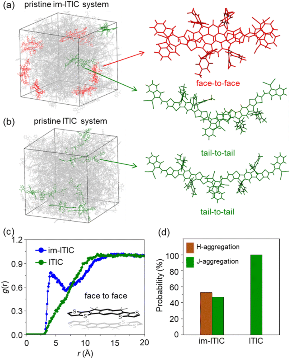 | ||
| Fig. 8 (a) and (b) Snapshots (left) and examples of stacking modes (right) from the MD results of im-ITIC and ITIC based pristine systems. (c) Radial distribution function data for pristine systems. (d) Probability of different aggregations in pristine systems. In the snapshots, face-to-face and tail-to-tail aggregations are colored red and green, respectively. | ||
Further, MD simulations for im-ITIC in pristine and blend states with different additives were also performed to understand the effect of additives on the molecular packing. As shown in Fig. S18,† the addition of DIO significantly increases the probability of face-to-face stacking in pristine im-ITIC systems. This phenomenon is also observed in blend systems (Fig. S19†). As shown in Fig. S18c and S19c,† a distinct peak at around 4 Å is present between CN and im-ITIC, whereas no such peak was observed between DIO and im-ITIC. This result indicates that DIO does not form intermolecular interactions with im-ITIC, thereby increasing the possibility of face-to-face stacking of im-ITIC compared with CN. As a result, the use of DIO additives contributed to enhancing the H-aggregation behavior of im-ITIC, which is a critical factor for achieving high VOC values in OSCs.
Excited state analysis
To further understand how H-aggregation increases VOC, we performed time-dependent DFT (TD-DFT) calculations using the ωB97XD/6-31G(d,p) method on D:A clusters with different stacking modes from MD simulations.39,47Fig. 9 displays the hole and electron distributions for the lowest CT and localized excited (LE) states in various aggregates between im-ITIC/ITIC and the PBDB-T fragment. The ECT values for H- and J-aggregates for im-ITIC-based clusters were calculated to be 2.06 and 1.97 eV, respectively. The ECT value for the J-aggregate of the ITIC-based cluster had a slightly lower value of 1.94 eV. These results indicate that J-aggregation produces similar CT states between im-ITIC and ITIC. In contrast, H-aggregation in im-ITIC significantly raises the ECT at the D/A interface. In addition, the energy offset (ΔELE−CT) between ECT and ELE for these clusters were calculated to be 0.10, 0.12 and 0.21 eV, respectively, indicating that H-aggregation possibly contributes to reducing the energy loss.49,50 Thus, we conclude that the H-aggregation in im-ITIC raises the overall energy level of the CT state in OSCs, achieved through a molecular design that incorporates steric hindrance on only one side of the molecule.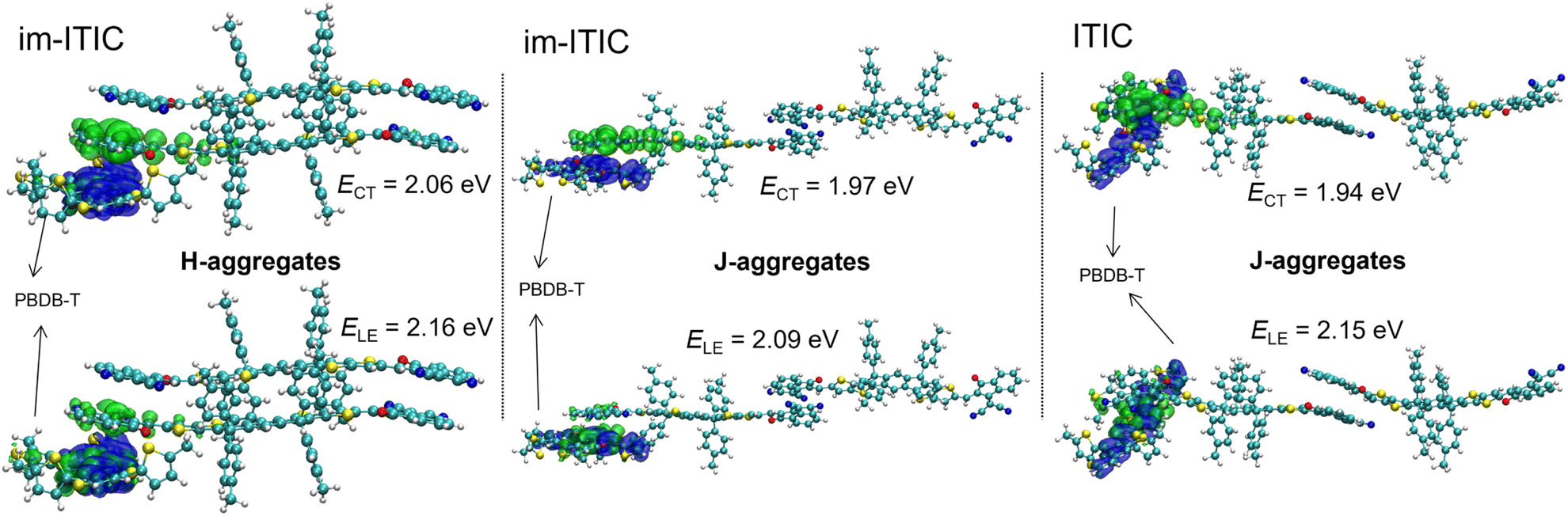 | ||
| Fig. 9 Distributions of the hole (blue) and electron (green) for different excited states of different aggregates of im-ITIC. TD-DFT calculations were performed using the ωB97XD/6-31G(d,p) method on the molecular clusters from MD simulations. | ||
Conclusions
To investigate the impact of aggregation behavior on VOC, we designed im-ITIC with C2v symmetry, arranging all the side chains on one side of ITIC. Concentration-dependent 1H NMR spectra of im-ITIC exhibit aggregation behavior in solution. LEIPS measurements revealed that EA values for im-ITIC and ITIC pristine films were almost identical to each other. Based on the IE, EA, and Eoptg values, the Eb values of im-ITIC and ITIC were estimated to be 0.36 and 0.40 eV, respectively. Single-crystal X-ray diffraction analysis revealed that im-ITIC exhibits H- and J-aggregates in the packing diagram. The PBDB-T:im-ITIC-based OSC showed a higher VOC of 1.02 V compared with that of PBDB-T:ITIC (0.90 V). The VOC of PBDB-T:im-ITIC was influenced by the choice of additives, showing higher VOC when DIO was employed. The ECT values of the PBDB-T:im-ITIC and PBDB-T:ITIC films were estimated to be 1.57 and 1.39 eV, respectively, demonstrating a positive correlation with the VOC values of OSCs. TR-IR measurements revealed that the lifetime of free carriers in the pristine im-ITIC film was longer than that of ITIC, while the lifetime of the PBDB-T:im-ITIC blend film was found to be shorter than that of the PBDB-T:ITIC film. These results align with the Eb values in pristine film and the JSC values of the blend films. Through MD simulations and TD-DFT calculations, we found that the H-aggregation behavior of im-ITIC substantially increases the ECT energy level at the D:A interface compared with J-aggregates, thereby improving VOC. This study demonstrated that the aggregation behavior induced by the molecular structure of acceptors influences the ECT and the VOC in OSCs, offering valuable insights for designing high-performance nonfullerene acceptors.Data availability
The data supporting this article have been included as part of the ESI.†Author contributions
All the authors have given approval to the final version of the manuscript.Conflicts of interest
There are no conflicts to declare.Acknowledgements
This work was supported by the Japan Society for the Promotion of Science (20H02814, 20H05841, 20KK0123, 23K17947, 20K15352, 23H02064, 20H05838, 24H00485, and 24H00482), New Energy and Industrial Technology Development Organization (215002 48-0), Japan Science and Technology Agency (JPMJMI22I1, JPMJSF23B3, and JPMJCR20R1), and Mitsubishi Foundation (202310004). We thank the Comprehensive Analysis Center (CAC), SANKEN, for assistance in performing elemental analyses and obtaining high-resolution mass spectra.Notes and references
- S. M. Lu, S. Amaducci, S. Gorjian, M. Haworth, C. Hägglund, T. Ma, S. Zainali and P. E. Campana, Joule, 2024, 8, 2483–2522 Search PubMed.
- S. Chatterjee, S. Jinnai and Y. Ie, J. Mater. Chem. A, 2021, 9, 18857–18886 RSC.
- S. Chatterjee, N. Shimohara, T. Seo, S. Jinnai, T. Moriyama, M. Saida, K. Omote, K. Hama, Y. Iimuro, Y. Watanabe and Y. Ie, Mater. Today Energy, 2024, 45, 101673 CrossRef CAS.
- S. Jinnai, N. Shimohara, K. Ishikawa, K. Hama, Y. Iimuro, T. Washio, Y. Watanabe and Y. Ie, Faraday Discuss., 2024, 250, 220–232 RSC.
- S. Jinnai, A. Oi, T. Seo, T. Moriyama, M. Terashima, M. Suzuki, K.-i. Nakayama, Y. Watanabe and Y. Ie, ACS Sustain. Chem. Eng., 2023, 11, 1548–1556 CrossRef CAS.
- L. Zhu, M. Zhang, Z. Zhou, W. Zhong, T. Hao, S. Xu, R. Zeng, J. Zhuang, X. Xue, H. Jing, Y. Zhang and F. Liu, Nat. Rev. Electr. Eng., 2024, 1, 581–596 CrossRef.
- S. Guan, Y. Li, C. Xu, N. Yin, C. Xu, C. Wang, M. Wang, Y. Xu, Q. Chen, D. Wang, L. Zuo and H. Chen, Adv. Mater., 2024, 36, 2400342 CrossRef CAS PubMed.
- Y. Sun, L. Wang, C. Guo, J. Xiao, C. Liu, C. Chen, W. Xia, Z. Gan, J. Cheng, J. Zhou, Z. Chen, J. Zhou, D. Liu, T. Wang and W. Li, J. Am. Chem. Soc., 2024, 146, 12011–12019 CrossRef CAS.
- L. Zhu, M. Zhang, G. Q. Zhou, Z. Y. Wang, W. K. Zhong, J. X. Zhuang, Z. C. Zhou, X. Y. Gao, L. X. Kan, B. N. Hao, F. Han, R. Zeng, X. N. Xue, S. J. Xu, H. Jing, B. Xiao, H. M. Zhu, Y. M. Zhang and F. Liu, Joule, 2024, 8, 3153–3168 CrossRef CAS.
- W. Shockley and H. J. Queisser, J. Appl. Phys., 1961, 32, 510–519 CrossRef CAS.
- Y. B. Kong, H. Z. Chen and L. J. Zuo, Adv. Funct. Mater., 2024, 2413864 Search PubMed.
- C. Deibel, T. Strobel and V. Dyakonov, Adv. Mater., 2010, 22, 4097–4111 CrossRef CAS PubMed.
- X. Y. Zhu, Q. Yang and M. Muntwiler, Acc. Chem. Res., 2009, 42, 1779–1787 CrossRef CAS.
- D. He, F. W. Zhao, C. R. Wang and Y. Z. Lin, Adv. Funct. Mater., 2022, 32, 2111855 CrossRef CAS.
- Y. H. Deng, W. Yuan, Z. Jia and G. Liu, J. Phys. Chem. B, 2014, 118, 14536–14545 CrossRef CAS PubMed.
- K. Cai, J. J. Xie, D. Zhang, W. J. Shi, Q. F. Yan and D. H. Zhao, J. Am. Chem. Soc., 2018, 140, 5764–5773 CrossRef CAS.
- Q. Q. Zhao, H. J. Lai, H. Chen, H. Li and F. He, J. Mater. Chem. A, 2021, 9, 1119–1126 RSC.
- S. Li, L. Y. Fu, X. X. Xiao, H. Geng, Q. Liao, Y. Liao and H. B. Fu, Angew. Chem., Int. Ed., 2021, 60, 18059–18064 CrossRef CAS.
- J. H. Kim, T. Schembri, D. Bialas, M. Stolte and F. Würthner, Adv. Mater., 2022, 34, 2104678 CrossRef CAS.
- Y. Z. Lin, J. Y. Wang, Z. G. Zhang, H. T. Bai, Y. F. Li, D. B. Zhu and X. W. Zhan, Adv. Mater., 2015, 27, 1170–1174 CrossRef CAS.
- Y. Shi, T. Suguri, C. Dohi, H. Yamada, S. Kojima and Y. Yamamoto, Chem.–Eur. J., 2013, 19, 10672–10689 CrossRef CAS PubMed.
- H. Yoshida, Chem. Phys. Lett., 2012, 539, 180–185 CrossRef.
- H. Yoshida, J. Electron Spectrosc. Relat. Phenom., 2015, 204, 116–124 CrossRef CAS.
- J. P. Yang, F. Bussolotti, S. Kera and N. Ueno, J. Phys. D: Appl. Phys., 2017, 50, 423002 Search PubMed.
- J. Liu, S. S. Chen, D. P. Qian, B. Gautam, G. F. Yang, J. B. Zhao, J. Bergqvist, F. L. Zhang, W. Ma, H. Ade, O. Inganäs, K. Gundogdu, F. Gao and H. Yan, Nat. Energy, 2016, 1, 16089 CrossRef CAS.
- H. Mori, S. Jinnai, Y. Hosoda, A. Muraoka, K. Nakayama, A. Saeki and Y. Ie, Angew. Chem., Int. Ed., 2024, 63, e202412691 CrossRef.
- K. Wang, S. Jinnai, T. Urakami, H. Sato, M. Higashi, S. Tsujimura, Y. Kobori, R. Adachi, A. Yamakata and Y. Ie, Angew. Chem., Int. Ed., 2024, 63, e202412691 CrossRef CAS PubMed.
- F. C. Spano, Acc. Chem. Res., 2010, 43, 429–439 CrossRef CAS.
- S. Giannini and J. Blumberger, Acc. Chem. Res., 2022, 55, 819–830 Search PubMed.
- W. C. Zhao, S. S. Li, H. F. Yao, S. Q. Zhang, Y. Zhang, B. Yang and J. H. Hou, J. Am. Chem. Soc., 2017, 139, 7148–7151 CrossRef CAS.
- Z. Zheng, E. F. He, J. Wang, Z. T. Qin, T. Q. Niu, F. Y. Guo, S. Y. Gao, Z. F. Ma, L. C. Zhao, X. H. Lu, Q. F. Xue, Y. Cao, G. T. Mola and Y. Zhang, J. Mater. Chem. A, 2021, 9, 26105–26112 RSC.
- G. G. Malliaras, J. R. Salem, P. J. Brock and J. C. Scott, Phys. Rev. B, 1999, 59, 10371 CrossRef CAS.
- C. Goh, R. J. Kline, M. D. McGehee, E. N. Kadnikova and J. M. J. Fréchet, Appl. Phys. Lett., 2005, 86, 122110 Search PubMed.
- S. D. Dimitrov and J. R. Durrant, Chem. Mater., 2014, 26, 616–630 CrossRef CAS.
- J. L. Wu, F. C. Chen, Y. S. Hsiao, F. C. Chien, P. L. Chen, C. H. Kuo, M. H. Huang and C. S. Hsu, ACS Nano, 2011, 5, 959–967 CrossRef CAS PubMed.
- C. M. Proctor, C. Kim, D. Neher and T. Q. Nguyen, Adv. Funct. Mater., 2013, 23, 3584–3594 CrossRef CAS.
- W. Zhao, D. Qian, S. Zhang, S. Li, O. Inganäs, F. Gao and J. Hou, Adv. Mater., 2016, 28, 4734 CrossRef CAS PubMed.
- A. Yamakata, K. Kato, T. Urakami, S. Tsujimura, K. Murayama, M. Higashi, H. Sato, Y. Kobori, T. Umeyama and H. Imahori, Chem. Sci., 2024, 15, 12686–12694 RSC.
- K. Wang, S. Jinnai, T. Urakami, H. Sato, M. Higashi, S. Tsujimura, Y. Kobori, R. Adachi, A. Yamakata and Y. Ie, Angew. Chem., Int. Ed., 2024, e202412691 CAS.
- S. Jinnai, K. Murayama, K. Nagai, M. Mineshita, K. Kato, A. Muraoka, A. Yamakata, A. Saeki, Y. Kobori and Y. Ie, J. Mater. Chem. A, 2022, 10, 20035–20047 RSC.
- A. Yamakata, T. Ishibashi and H. Onishi, Chem. Phys. Lett., 2001, 333, 271–277 CrossRef CAS.
- A. Yamakata, M. Kawaguchi, N. Nishimura, T. Minegishi, J. Kubota and K. Domen, J. Phys. Chem. C, 2014, 118, 23897–23906 CrossRef CAS.
- J. I. Pankove, Optical Processes in Semiconductors, Dover, 1975 Search PubMed.
- L. Ye, H. W. Hu, M. Ghasemi, T. H. Wang, B. A. Collins, J. H. Kim, K. Jiang, J. H. Carpenter, H. Li, Z. K. Li, T. McAfee, J. B. Zhao, X. K. Chen, J. L. Y. Lai, T. X. Ma, J. L. Bredas, H. Yan and H. Ade, Nat. Mater., 2018, 17, 253–260 CrossRef CAS PubMed.
- Y. K. Li, Y. Guo, Z. Chen, L. L. Zhan, C. L. He, Z. Z. Bi, N. N. Yao, S. X. Li, G. Q. Zhou, Y. P. Yi, Y. Yang, H. M. Zhu, W. Ma, F. Gao, F. L. Zhang, L. J. Zuo and H. Z. Chen, Energy Environ. Sci., 2022, 15, 855–865 RSC.
- G. C. Han and Y. P. Yi, Acc. Chem. Res., 2022, 55, 869–877 CrossRef CAS PubMed.
- G. C. Zhang, X. K. Chen, J. Y. Xiao, P. C. Y. Chow, M. R. Ren, G. Kupgan, X. C. Jiao, C. C. S. Chan, X. Y. Du, R. X. Xia, Z. M. Chen, J. Yuan, Y. Q. Zhang, S. F. Zhang, Y. D. Liu, Y. P. Zou, H. Yan, K. S. Wong, V. Coropceanu, N. Li, C. J. Brabec, J. L. Bredas, H. L. Yip and Y. Cao, Nat. Commun., 2020, 11, 3943 Search PubMed.
- V. Coropceanu, X. K. Chen, T. H. Wang, Z. L. Zheng and J. L. Brédas, Nat. Rev. Mater., 2019, 4, 689–707 CrossRef.
- L. L. Zhan, S. X. Li, Y. K. Li, R. Sun, J. Min, Y. Y. Chen, J. Fang, C. Q. Ma, G. Q. Zhou, H. M. Zhu, L. J. Zuo, H. Y. Qiu, S. C. Yin and H. Z. Chen, Adv. Energy Mater., 2022, 12, 2201076 CrossRef CAS.
- F. D. Eisner, M. Azzouzi, Z. P. Fei, X. Y. Hou, T. D. Anthopoulos, T. J. S. Dennis, M. Heeney and J. Nelson, J. Am. Chem. Soc., 2019, 141, 6362–6374 CrossRef CAS.
- T. J. Aldrich, M. Matta, W. G. Zhu, S. M. Swick, C. L. Stern, G. C. Schatz, A. Facchetti, F. S. Melkonyan and T. J. Marks, J. Am. Chem. Soc., 2019, 141, 3274–3287 CrossRef CAS.
Footnote |
| † Electronic supplementary information (ESI) available. See DOI: https://doi.org/10.1039/d5ta00178a |
| This journal is © The Royal Society of Chemistry 2025 |