
 Open Access Article
 This Open Access Article is licensed under a Creative Commons Attribution-Non Commercial 3.0 Unported Licence
Ordered mesoporous electrocatalysts for highly selective formate production from electrocatalytic CO2 reduction†
Ashfaq
Ahamd‡
,
Chaoran
Zhang‡
 ,
Yichuan
Gu
,
Qu
Jiang
,
Ziyang
Sheng
,
Ruohan
Feng
,
Sihong
Wang
,
Haoyue
Zhang
,
Qianqing
Xu
,
Zijian
Yuan
and
Fang
Song
*
,
Yichuan
Gu
,
Qu
Jiang
,
Ziyang
Sheng
,
Ruohan
Feng
,
Sihong
Wang
,
Haoyue
Zhang
,
Qianqing
Xu
,
Zijian
Yuan
and
Fang
Song
*
State Key Laboratory of Metal Matrix Composites, School of Materials Science and Engineering, Shanghai Jiao Tong University, Shanghai 200240, China. E-mail: songfang@sjtu.edu.cn
First published on 7th March 2025
Abstract
Ordered mesoporous materials offer significant advantages in reducing energy barriers, tuning intrinsic reaction pathways, and suppressing undesirable side reactions in electrocatalytic CO2 reduction reactions (CO2RR). Here, we present a straightforward method for the direct electrodeposition of ordered mesoporous CO2RR catalysts on a carbon-based porous transport layer, utilizing lyotropic liquid crystals (LLCs) as templates. The versatility of this method was demonstrated with tin-, bismuth-, and indium-based catalysts, all exhibiting pore sizes on the order of several nanometers. These ordered mesoporous catalysts efficiently and selectively drive CO2RR toward the value-added product of formate. They achieve partial current densities that are 3 to 8 times higher than those of disordered mesoporous reference samples, with a faradaic efficiency (FE) of up to 93% at an optimal potential of −0.9 V vs. RHE. In a flow cell configuration, Sn-based catalysts deliver a current density of ∼200 mA cm−2 over 22 hours at a potential of only −0.65 V vs. RHE. Spectroscopic and electrochemical analyses suggest that the high performance can be attributed to the exclusive exposure of active sites for the formate, improved mass transport, and modulated local microenvironments. Our work demonstrates a simple yet effective method for the direct deposition of efficient and selective catalysts onto electrodes. The insights gained from the underlying mechanisms provide valuable guidance for the design of high-performance CO2RR electrocatalysts.
1. Introduction
Producing value-added chemicals through the electrochemical CO2 reduction reaction (CO2RR) coupled with intermittent renewable energy represents a significant pathway to mitigate excessive CO2 emissions in the atmosphere.1–3 Electrocatalysts play a pivotal role in overcoming the high energy barriers associated with driving the selective production of specific products.3,4 Among the various potential products, formate (HCOO−) and formic acid (HCOOH) are particularly important, as they serve as excellent liquid hydrogen carriers and key feedstocks in the textile and agricultural industries.5–8 Electrocatalysts based on tin (Sn),9–11 bismuth (Bi),12,13 indium (In),14,15 and lead (Pb)16 have emerged as excellent candidates for the high-selectivity production of formate. Considerable efforts have been dedicated to regulating the electronic structures of these catalysts to enhance both efficiency and selectivity.17In addition to the intrinsic characteristics of the catalysts determined by their physical and chemical properties, the microstructure plays a crucial role in regulating selectivity and activity.18 Compared to macro- and micro-porous structures, mesoporous structures represent an excellent compromise, balancing high surface area with rapid mass transport.18 This has led to considerable research interest in applying mesoporous materials to CO2RR catalysis. Mesoporous structures not only increase surface area but also enhance mass and charge transport.9,19–21 Additionally, they can modulate the electronic structures of curved surfaces, thereby improving intrinsic catalytic activity.22–24 For instance, in mesoporous noble metal catalysts such as silver (Ag) and gold (Au), high-index facets with a high density of under-coordinated atoms are found at edges, steps, and kinks, which serve as exceptional active sites for CO2RR catalysis.22–25 In the case of metal oxides and their derivatives, the formation of amorphous surfaces can lead to optimal binding energies for reaction intermediates, as well as the creation of numerous atomic deficiencies, including oxygen vacancies, which facilitate efficient and selective CO2RR catalysis.11,26 More importantly, mesoporous structures can influence catalytic performance by modulating local microenvironments.23,27–29 Research has shown that diffusional or pH gradients within mesopores can tune catalytic activity and selectivity,27,28,30 allowing reactants or intermediates to be retained for extended periods, thereby increasing the likelihood of reactions occurring.29,31,32 These phenomena present a new and comprehensive approach to the rational optimization and design of efficient CO2RR catalysts. However, synthesizing mesoporous CO2RR catalysts, particularly ordered mesoporous ones, remains a significant challenge.
Lyotropic liquid crystals (LLCs) have gained recognition for their tunable ordered nanoporous structures and compatibility with various synthetic methods, including electrodeposition, electroless deposition, and wet-chemical synthesis, making them excellent templates for synthesizing mesoporous metals, alloys, and oxide derivatives.33–41 These materials have demonstrated promising applications in catalytic hydrogen and oxygen evolution, methanol oxidation, supercapacitors, and sensors. However, despite the effectiveness of mesoporous structures in enhancing CO2RR performance, LLCs have seldom been explored for producing CO2RR electrocatalysts. This gap presents a valuable opportunity for further research. To fabricate mesoporous structures, various methods like soft and hard templating, self-templating, leaching, and dealloying have been employed, yielding pore sizes from several nanometers to hundreds of nanometers.18,42 Yet, these processes often face challenges: soft and hard templating typically requires energy-intensive steps for template removal, which can result in the loss of active sites and the collapse of mesopores.10,11,21 Although self-templating and leaching methods avoid these issues, they often inadequately tune pore size and organization or retain surface active sites.9 Conversely, the dealloying process proves to be the most effective approach, producing well-organized nanopores and a high density of catalytic active under-coordinated atoms.22–24 However, it is limited to specific metals and alloys like gold (Au), silver (Ag), palladium (Pd), and copper (Cu), which are favorable for selectively producing CO and C2/C3 products. Additionally, ordered mesoporous catalysts such as Sn, Bi, and In remain underexplored for the selective production of formate or formic acid, indicating further potential avenues for research in this area.9–15
In this work, we report the use of lyotropic liquid crystal (LLC)-templating-assisted electrodeposition to create ordered mesoporous self-supporting catalysts on electrodes, aimed at the efficient and selective production of formate. We successfully synthesize ordered mesoporous catalysts based on tin (Sn), bismuth (Bi), and indium (In), and we investigate the influence of their microstructures on catalytic performance. Ordered mesoporous structures demonstrate partial current densities that are 3 to 8 times higher than those of disordered mesoporous reference samples, achieving faradaic efficiencies (FEs) ranging from 85% to 93.5% at their respective optimal potentials. Furthermore, we examine ordered mesoporous SnOx catalysts in a flow cell configuration to assess their potential for practical applications. These catalysts yield a current density of ∼206 mA cm−2 durable for 22 hours at a potential of −0.65 V vs. RHE. Spectroscopic and electrochemical analyses reveal the underlying mechanisms, suggesting that the exclusive exposure of active sites for the formate, enhanced mass transport, reactant/intermediate confinement, and localized pH modulation collectively contribute to the improved catalytic performance for CO2RR. This work demonstrates the effectiveness of LLC-templating in synthesizing efficient CO2RR catalysts for selective formate production. Moreover, this approach could be adapted for other catalysts, particularly those aimed at producing multi-carbon products, as such structures are particularly advantageous for enhancing catalytic activity.
2. Experimental section
2.1 Reagents and materials
All reagents and materials were used directly with no further purification. Methanesulfonic acid (CH4O3S, 99%), tin(II) sulfate (SnSO4, AR), bismuth acetate (Bi(C2H3O2)3, 99.9%), indium acetate (In(C2H3O2)3, 99.99%), Brij® C10 (Brij 56, average Mw = ∼683), were purchased from Shanghai Aladdin Biochemical Technology Co., Ltd. Nafion® (D520) dispersion was purchased from Dupont. Nickel foam, Sigracet 28BC carbon paper with a gas diffusion layer, and the anion exchange membranes (FAA-3-50, Fumapem, and Sustainion® X37-50 Grade RT, Dioxide Material) were purchased from the Fuel Cell Store.2.2 Synthesis of ordered mesoporous tin, bismuth, and indium oxide (SnOx-om, BiOx-om, and InOx-om)
Mesoporous tin was electrodeposited from an electrolyte containing 50 wt% Brij 56, 0.2 M SnSO4, and methane sulphonic acid. The samples were deposited at −0.2 V vs. SCE at 40 °C on carbon paper, and a homogeneous layer was formed. The total charge during the electrodeposition was fixed at 2C using a chronocoulometry. After deposition, carbon paper bearing the electrodeposited tin oxide was kept in absolute ethanol to remove the residual surfactant. Then, the samples were rinsed with distilled water and dried in a vacuum at 60 °C for further use. The synthesis of BiOx-om and InOx-om can be fulfilled by altering SnSO4 with bismuth acetate and indium acetate, respectively.2.3 Synthesis of disordered mesoporous tin, bismuth, and indium oxide (SnOx-dom, BiOx-dom, and InOx-dom)
The disordered mesoporous samples were electrodeposited on carbon paper using the same parameters, the only difference in the precursor was the removal of lyotropic template reagent Brij 56. Then the chronocoulometry was used to deposit the catalysts on carbon paper. After being rinsed with water and dried, the disordered mesoporous samples were prepared for further electrochemical tests.2.4 Materials characterizations
The crystallographic information of samples was collected by Mini Flex 600 with Cu Kα irradiation (λ = 1.5406 Å) at 40 kV and 40 mA in the 2θ range of 5 to 80° with a scanning rate of 10° min−1. Small angel X-ray diffraction (SAXRD) was tested using a Bruker D8 ADVANCE with Cu Kα irradiation (λ = 1.5406 Å) at 40 kV and 40 mA in the 2θ range of 0.5 to 5° with a scanning rate of 0.8° min−1. TESCAN MIRA3 field emission scanning electron microscopy (FE-SEM) equipped with energy dispersive spectroscopy (EDS) was applied to confirm the morphology and elements of the products. Transmission electron microscopy (TEM) and high-resolution transmission electron microscopy (HRTEM) were collected by Talos F200X G2 FETEM under an acceleration voltage of 200 kV. X-ray photoelectron spectroscopy (XPS) analysis was obtained by AXIS Ultra DLD and all spectra were corrected using the C 1s line at 284.6 eV. Fourier-transformed infrared spectroscopy (FTIR, Nicolet 6700, Thermo Fisher) spectra were collected to indicate the structural information of different samples. Nitrogen sorption isotherms were measured on an ASAP 2460 (Micromeritics Instrument Corp., USA).2.5 Electrochemical measurements
All electrochemical measurements were carried out on a Gamry Reference 3000 electrochemical instrument. The automatic iR compensation (85%) was used. Ag/AgCl electrode with a 3.5 M KCl filling solution was used as the reference electrode. Potential versus RHE was calculated as Evs.RHE = Evs.Ag/AgCl + 0.2046 V + 0.0592 V × pH. The pH values of the electrolytes were measured by a pH meter (FE28 Standard, Mettler Toledo). The pH values of CO2 and N2 saturated 0.1 M KHCO3 electrolytes used in this work are 6.86 and 8.48, respectively.A carbon paper with a gas diffusion layer (Sigracet 28BC, SGL) was used as the working electrode for electrolysis at a constant potential. The area exposed to the electrolyte was fixed at 1 cm2. The electrodeposition process was initiated in a cell with target salts. The total charge was fixed at 2C during the preparation.
An H-type cell made of glass was used. Working and reference electrodes were fixed in one chamber and the counter electrode was fixed in the other chamber. The two chambers were separated by an anion exchange membrane (Fumapem FAA-3-50). A bubble sieve was fixed at the gas inlet to generate small bubbles. A Pt plate was used as the counter electrode. 0.1 M KHCO3 electrolyte was used for both chambers.
A flow cell system was assembled using the catalysts as working electrodes, Ag/AgCl (3.5 M KCl-filled) electrode as reference electrode, and nickel foam as counter electrode. The flow cell electrolyzer comprises polyetheretherketone (PEEK) and a silicone gasket for sealing. The gas flow rate was fixed at 10 s.c.c.m. using a mass-flow controller (Sevenstar CS-200A). The CO2 gas flows from the back of the carbon paper to the catalyst side to participate in the reaction. The catholyte and anolyte were 1 M KOH and separated by a Sustainion® X37-50 film (Grade RT), the flow rate was adjusted to 10 mL min−1 by a peristaltic pump.
2.6 Products analysis
Gas products were detected and quantified via gas chromatography (Trace 1310, Thermo Fisher Scientific, USA), including CO, CH4, C2H4, C2H6 and H2. Three GC columns (Porapak N, TG-BOND Q+, and Molesieve 5A) are used to separate different gases.Faradaic efficiency (FE) can be obtained with:

Faradaic efficiency (FE) can be obtained with:

![[thin space (1/6-em)]](https://www.rsc.org/images/entities/char_2009.gif) 485 C mol−1, Q is the total charge during the reaction, xi is the fraction of products detected by GC, p is the ambient pressure, V0 is the analyzed gas volume in GC, T is the ambient temperature, ∫Idt is the integrated charge, VL is the catholyte volume, C is the molar concentration of liquid products in the sampling solution.
485 C mol−1, Q is the total charge during the reaction, xi is the fraction of products detected by GC, p is the ambient pressure, V0 is the analyzed gas volume in GC, T is the ambient temperature, ∫Idt is the integrated charge, VL is the catholyte volume, C is the molar concentration of liquid products in the sampling solution.
3. Results and discussion
3.1 Synthesis and microstructures of ordered mesoporous catalysts
Ordered mesoporous oxides were electrochemically deposited on carbon paper with a gas diffusion layer using a lyotropic liquid crystal (LLC) known as Brij 56 as a hard template (see details in the Experimental section).43 The LLC templates were subsequently rinsed off using ethanol and isopropyl alcohol. The synthetic procedure is illustrated in Fig. 1a. The deposition process was monitored using Field-Emission Scanning Electron Microscopy (FESEM) and Energy-Dispersive X-ray Spectroscopy (EDX) mapping analysis (Fig. S1a–c†). Throughout the process, a dense film was observed, exhibiting a progressively increasing surface roughness from the Brij 56 template to the catalysts deposited on Brij 56, and finally to the mesoporous catalysts. For comparison, disordered mesoporous metal oxides were synthesized using a similar method but without the LLC template. We utilized ordered mesoporous tin oxide (SnOx-om) and disordered one (SnOx-dom) as representative samples to illustrate the differences in the microstructure.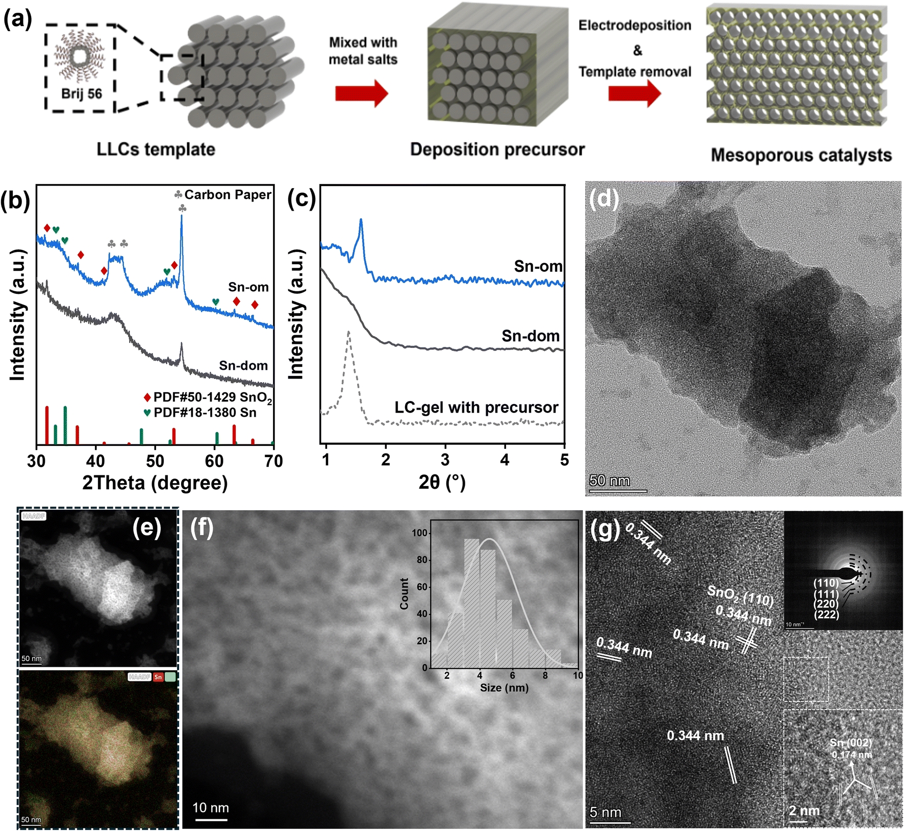 | ||
| Fig. 1 Synthesis and microstructures of ordered mesoporous SnOx. (a) Schematic illustration of the synthetic process using liquid crystals of Brij 56 as templates; (b) PXRD patterns; (c) SAXRD patterns; (d) TEM image of SnOx-om; (e) HAADF image and corresponding EDS mapping of SnOx-om. The spatial distributions of Sn and O are depicted in red and green, respectively (Fig. S2†). The yellow coloration arises from the blending of these colors, indicating a homogeneous distribution of tin and oxygen; (f) Magnified HAADF image of SnOx-om. The inset shows the pore size distribution; (g) HRTEM image of SnOx-om. The inset shows the corresponding SAED pattern. | ||
Powder X-ray diffraction (PXRD) patterns (Fig. 1b) indicate that both ordered mesoporous tin oxide (SnOx-om) and disordered tin oxide (SnOx-dom) exhibit low crystallinity. The weak peaks observed at 31.8°, 36.9°, 41.4°, 53.1°, 63.3°, and 66.4° correspond to the (111), (200), (210), (220), (311), and (222) planes of standard SnO2 (PDF # 50-1429).11,44 Broadened peaks at 33.2°, 34.8°, and 52.5° signify the presence of minor metallic tin (PDF # 18-1380) in SnOx-dom. Fourier-transform infrared spectroscopy (FTIR) analysis indicates the complete removal of LLC templates, as the characteristic peaks of Brij 56 surfactant disappear in SnOx-om (Fig. S1d†). The peaks at 1145 cm−1 and 1040 cm−1 can be attributed to the carbon paper substrate, while the peak at 670 cm−1 corresponds to the Sn–O vibrational mode. Small-angle X-ray diffraction (SAXRD) patterns reveal a peak at 1.58 degrees (Fig. 1c), providing strong evidence for the formation of ordered nanoporous structures. Using Bragg's equation, we estimate a pore size of 2.4–4.3 nm for SnOx-om, which is consistent with the sizes of other mesoporous metals and alloys fabricated using the same templating method.18 The LLCs-gel containing the Sn precursor also exhibits a distinct peak, although it shifts to a larger angle compared to SnOx-om, indicating a reduction in pore size during the electrochemical deposition process. In contrast, no sharp peak is observed in SnOx-dom. The N2 adsorption–desorption isotherm (Fig. S1e†) shows a pronounced IV-type hysteresis loop for SnOx-om, which contrasts with the smaller loop seen for SnOx-dom. The larger hysteresis loop indicates the presence of abundant mesopores in SnOx-om. The pore size distribution curve reveals a dominant pore size of approximately 3.7 nm (inset in Fig. S1e†), consistent with the value estimated from SAXRD data.
The transmission electron microscopy (TEM) image (Fig. 1d) and the corresponding high-angle annular dark field (HAADF) image (Fig. 1e) reveal a sponge-like morphology for SnOx-om.45 Highly porous structures are distinguishable in the magnified HAADF image (Fig. 1f), and the size distribution indicates an average pore size of approximately 4.6 nm (inset in Fig. 1f). The high-resolution TEM (HRTEM) image (Fig. 1g) displays a distinct lattice spacing of 0.334 nm, corresponding to the (110) plane of SnO2. The indeterminate lattice fringes indicate that SnOx-om is composed of small nanoclusters with varying orientations. The selected area electron diffraction (SAED) pattern (top-left inset in Fig. 1g) exhibits concentric circles, consistent with a polycrystalline nature. These concentric circles are indexed to the (110), (111), (220), and (222) facets of SnO2. Additionally, small metallic Sn nanocrystals with lattice fringes corresponding to the (002) planes are observed within SnOx-om (bottom-right inset in Fig. 1f). EDX mapping confirms the uniform distribution of tin and oxygen throughout SnOx-om, as evidenced by the yellow hue produced by blending red (Sn) and green (O) in the bottom panels of Fig. 1e and S2†. For comparison, SnOx-dom was characterized in the same manner (Fig. S3e and f†). SnOx-dom consists of SnO2 nanocrystals, with compositions and dimensions similar to those of SnOx-om;45 however, it lacks the ordered mesoporous structure observed in SnOx-om.
3.2 Electrocatalytic performances towards CO2 reduction reaction (CO2RR)
The electrochemical behavior of mesoporous SnOx was initially evaluated in an H-cell setup under both Ar and CO2 atmospheres (Fig. S4†). The distinct polarization curves reveal significant catalytic activity for the Sn-based catalysts in the CO2 atmosphere, while the hydrogen evolution reaction predominates in the Ar atmosphere. Notably, SnOx-om initiates CO2RR at a more positive potential than SnOx-dom, delivering a substantially higher current density at a specific potential, indicating its superior CO2RR activity. We investigated the potential-dependent catalytic activity within a range of potentials from −0.6 V to −1.2 V vs. RHE (Fig. 2, S5a and b, Tables S1 and S2†). The primary products of electrochemical CO2 reduction in both samples are formate and CO, with hydrogen detected as a side product from the hydrogen evolution reaction (Fig. S5a–c†). Partial current densities for each product were calculated (Fig. 2a, b and S5d†), showing an increasing trend with more negative applied potentials. Importantly, SnOx-om exhibits a much faster increase in the partial current density of formate compared to SnOx-dom, demonstrating distinct selectivity (Fig. 2c). In particular, at −1.0 V, SnOx-om achieves a faradaic efficiency greater than 85% with a partial current density of 25 mA cm−2, which is 2 to 8 times that of SnOx-dom.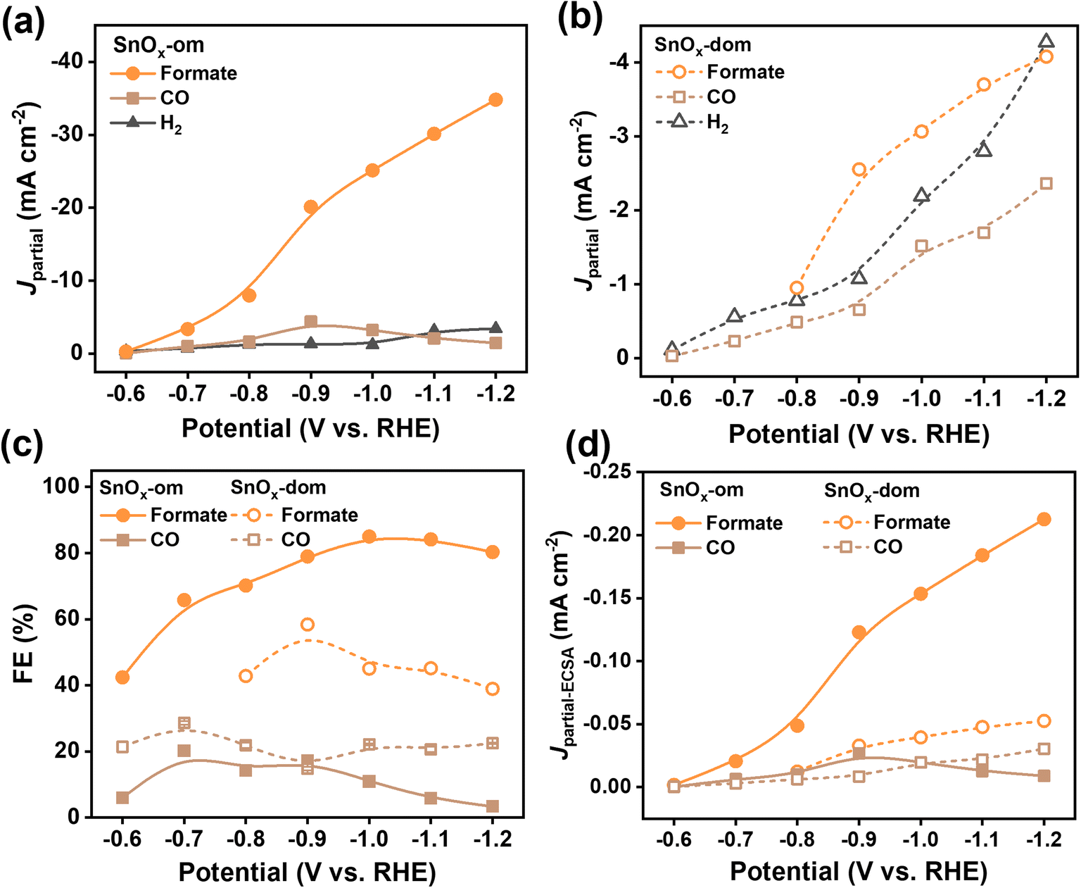 | ||
| Fig. 2 Electrocatalytic performance of mesoporous SnOx towards CO2 reduction in an H-cell. (a and b) Partial current densities plotting against applied potentials for (a) SnOx-om and (b) SnOx-dom; (c) faradaic efficiency plotting against applied potentials; (d) ECSA-normalized partial current densities plotting against applied potentials. | ||
To elucidate the underlying reasons for the enhanced activity towards formate production, we calculated the specific activities by normalizing the partial current densities with respect to the electrochemical surface area (ECSA, Fig. S6†). The specific activities show a four-fold increase for formate production in SnOx-om compared to SnOx-dom, while the specific activities for other minor products are relatively similar between the two. This suggests that SnOx-om contains highly active sites that selectively produce formate (Fig. 2d). Moreover, the dependence of partial current density on the applied potential for SnOx-om mirrors that of SnOx-dom, indicating that while the active sites may share similar electronic structures, they differ significantly in quantity. Additionally, we observed suppression of CO and H2 production in SnOx-om, with diminished faradaic efficiencies for these byproducts compared to SnOx-dom. This suppression is attributed to the diffusion gradients inherent in the ordered mesoporous structures, a phenomenon previously demonstrated in mesoporous Au and Ag catalysts.27,28,30
To evaluate the applicability of the LLCs-templating strategy to other catalysts, mesoporous bismuth oxide (BiOx) and indium oxide (InOx) were synthesized for CO2RR catalysis using the same electrochemical deposition method with LLCs as templates. TEM images confirm the formation of mesoporous structures in both BiOx-om and InOx-om (Fig. S7†). Notably, the structures of these oxides differ from that of SnOx-om, which can be attributed to the flexibility of the LLC templates, as the microstructure may vary due to different interactions between the LLCs and the precursor metal ions.45 Similar to SnOx catalysts, the ordered mesoporous BiOx and InOx significantly enhance CO2RR electrolysis compared to their disordered counterparts (Fig. 3, S8 and S9†). The ordered structures demonstrate an onset potential that is 100–170 mV more positive than that of the disordered samples and show much greater selectivity for formate production. At optimal potentials ranging from −1.0 to −1.1 V vs. RHE, BiOx-om achieves faradaic efficiencies (FEs) of 91–93% at partial current densities of 17–24 mA cm−2, in contrast to FEs of 48–51% with a partial current density of 8 mA cm−2 for BiOx-dom (Fig. 3a, c and e and Tables S3 and S4†). Likewise, InOx-om displays FEs of 84–86% towards formate at partial current densities of 10–15 mA cm−2, while InOx-dom only achieves FEs of 27–34% at partial current densities of less than 3 mA cm−2 (Fig. 3b, d and f and Tables S5 and S6†). Furthermore, the ordered mesoporous samples exhibit current density and FE dependencies on potential that are similar to those of their disordered counterparts (BiOx-om and BiOx-dom, as well as InOx-om and InOx-dom). This suggests that the active sites for the Bi and In-based samples may have similar electronic structures but differ significantly in quantity.
 | ||
| Fig. 3 Electrocatalytic performance of mesoporous BiOx and InOx towards CO2 reduction in a H-cell. (a–d) Partial current densities plotting against applied potentials for (a) BiOx-om, (b) InOx-om, (c) BiOx-dom, and (d) InOx-dom; (e and f) faradaic efficiency plotting against applied potentials for (e) BiOx-om and (f) InOx-om. | ||
3.3 Insights into the selectivity of ordered mesoporous catalysts
The above catalytic results have shown that each type of catalyst, including SnOx-om, BiOx-om, and InOx-om, as well as their disordered counterparts (SnOx-dom, BiOx-dom, and InOx-dom), exhibits similar potential-dependent activity across all products. This suggests that each catalyst pair may share the same type of active sites for each product, differing primarily in the quantity of these sites. This deduction is reasonable, as all catalysts were synthesized through similar processes, with the only distinction being the presence or absence of the LLC template. Consequently, the relative partial current density of the ordered mesoporous catalysts compared to the disordered ones can serve as an indicator of the relative number of specific active sites—provided the total current is low enough that local pH gradients do not significantly influence the electrochemical environment. Based on this analysis, we estimate that the active site densities for SnOx-om, BiOx-om, and InOx-om are approximately 8–9, 1.5–4, and 5–10 times greater than those of their corresponding disordered counterparts, respectively, specifically for formate production (Fig. S10†).X-ray photoelectron spectroscopy (XPS) was performed to investigate the surface properties of the catalysts, providing valuable insights into the distinct catalytic performances observed (Fig. 4a and b). High-resolution XPS of the Sn 3d and O 1s regions reveals that the surfaces of both SnOx-om and SnOx-dom are primarily composed of SnO2, with characteristic peaks for Sn4+ located at 487.6 eV and 496.0 eV. In contrast, SnOx-om contains a higher amount of Sn2+, indicated by characteristic peaks at 486.9 eV and 495.4 eV, as well as metallic Sn0 at 485.2 eV and 493.8 eV. The atomic ratio of Sn4+:Sn2+:Sn0 is approximately 1:0.45:0.25. The presence of low-valence Sn species can be attributed to the partial loss of lattice oxygen from the surface.46,47 The small amount of metallic Sn is consistent with the previous TEM results. The O 1s spectrum shows peaks corresponding to O–Sn4+ at 531.5 eV, O–Sn2+ at 529.6 eV, and absorbed H2O at 532.7 eV. The relative ratio of O–Sn4+:O–Sn2+ is approximately 1:0.39, closely aligning with the Sn4+:Sn2+ calculated from the Sn 3d spectra. The O–Sn2+ peak likely originates from Sn–OH moieties, formed by the insertion of OH− into oxygen defects.46–48 This correlates well with the presence of numerous oxygen defects in SnOx-om, further supported by the increased amount of absorbed H2O, which is readily adsorbed by these defects. The distinct surface properties of SnOx-om are attributed to the specific interactions between the catalysts and LLCs during the particle growth process. These differences in surface characteristics reinforce the conclusion that while MOx-om and MOx-dom share the same type of active sites, they differ in the number of active sites available for each product. The presence of low-valence Sn species is believed to contribute to the high selectivity for formate production.49 Similarly, abundant oxygen vacancies have been proposed to account for the high activity and selectivity observed in chemically reduced SnO2 nanosheets, where theoretical calculations indicated a decrease in the adsorption energy of HCOOH−* by 0.29 eV and HCOOH by 0.17 eV.26,49 Additionally, mesoporous structures have the capability to modulate the electronic configurations of curved surfaces in noble metal catalysts, such as silver (Ag) and gold (Au), where high-index facets characterized by a high density of under-coordinated atoms at edges, steps, and kinks act as exceptional active sites for CO2RR catalysis.22–24 This electronic structure regulation may also apply to SnOx-om and warrants further in-depth investigation.
 | ||
| Fig. 4 Correlation of the selectivity to microstructures of mesoporous catalysts. (a and b) High-resolution XPS of (a) Sn 3d and (b) O 1s; (c) DRT results for electrochemical impedance at −1.0 V vs. RHE. Inset in (c) is the enlarged view of IF and HF region; (d and e) Nyquist plots of (d) SnOx-om and (e) SnOx-dom. Insets in (d) and (e) are corresponding equivalent circuit models. | ||
Electrochemical impedance spectroscopy (EIS) was performed over a potential range of −0.6 to −1.2 V vs. RHE to investigate the dynamics of the electrodes (Fig. S11†). The EIS data were analyzed using distributed relaxation time (DRT) analysis (Fig. 4c and S11†),19,50,51 which categorizes internal resistance related to specific physical processes across varying time scales, eliminating the need for a predetermined equivalent circuit.52 The catalysts exhibited more than three distinct phenomena in the EIS, attributed to different processes: mass transport in the low-frequency (LF, <10 Hz) region, charge transfer in the intermediate-frequency (IF, 100 Hz–1 kHz) region, and ionic/electronic transport in the high-frequency (HF, >1 kHz) region. Notably, the HF resistance indicates that SnOx-om demonstrates superior electronic transport compared to SnOx-dom. Moreover, the smaller IF resistance of SnOx-om correlates with the faster electrocatalytic kinetics observed compared to SnOx-dom, with the hydrogen evolution reaction (HER) dominating at potentials above −0.7 V vs. RHE and CO2RR beginning to contribute at more negative potentials. In terms of LF resistances, SnOx-om shows a significant advantage over SnOx-dom at each potential. The low LF resistance of SnOx-om effectively underscores the benefits of its ordered mesoporous structure for facilitating rapid mass transport compared to the disordered structure. Notably, as the potential increases to −1.0 V, SnOx-om reduces its LF resistance by more than tenfold, while SnOx-dom only exhibits a two-fold decrease (Fig. S11e and f†). At −1.0 V, SnOx-om displays a resistance approximately one-fifth that of SnOx-dom, while achieving catalytic reaction rates that are eight times faster. These results collectively suggest that the ordered mesoporous structures of SnOx-om enhance the mass transport of reactants (CO2, H2O and H+) and products (formate, CO, and H2), significantly improving its apparent catalytic activity.
Additionally, we analyzed the data using an equivalent circuit model to further elucidate the differences between SnOx-om and SnOx-dom during CO2 reduction (Fig. 4d and e). We selected −0.6, −1.0, and −1.2 V vs. RHE as three typical potentials for a brief discussion (Fig. S12a–c and Table S7†). A simplified interfacial adsorption model was employed to quantify the adsorption/desorption behavior at the catalyst interface. RΩ and Cdl correspond to the solution resistance and double-layer capacitance, respectively, while Rs represents charge transfer resistance governed by the adsorption/desorption process of intermediates. Rp relates to resistance associated with charge transfer, and CΦ denotes the charge relaxation of adsorbed intermediates. Enhanced charge transfer and adsorption/desorption processes are observed for SnOx-om, particularly at optimal potentials, in line with previous DRT analysis. At the optimal potential, SnOx-om exhibits moderate Cdl, relatively high CΦ, and low Rp, indicating efficient charge transfer characteristics and effective intermediate adsorption/desorption. This supports our assertion that the mesoporous structure plays a critical role in facilitating both mass and charge transfer during CO2RR.
Similarly, the three-dimensional (3D) hierarchical mesoporous structure of SnO2 nanosheets provides a high surface area and facilitates mass transport, enabling them to function as robust and flexible electrodes for the electroreduction of CO2 to formate.9 This structure achieves a partial current density of approximately 45 mA cm−2 at a moderate overpotential of 0.88 V, along with a high FE of 87 ± 2%. In addition to mesoporous catalysts, solid catalytic nanoparticles can also be supported on various porous substrates.19–21 For example, a highly ordered porous substrate was employed to support a single-atom Fe–N–C catalyst, resulting in a maximum CO partial current density of −19 mA cm−2 in an H-cell.19 Additionally, Cu nanorods loaded onto organic cages achieved a faradaic efficiency for C2+ products of 76.1% with a current density of 1.7 A cm−2.19 Compared to macro- and micro-porous structures, ordered mesoporous structures offer an excellent compromise by balancing high surface area with rapid mass transport.18
In the electrochemical CO2RR conducted in an H-cell, the formation of diffusion and pH gradients on the reaction surface is often inevitable, particularly when catalyzing at high current densities. Previous studies have highlighted the significant role of pH gradients in regulating both catalytic activity and selectivity.53 In the reaction pathway for formate production, CO2 is reduced via a decoupled proton-electron transfer reaction (in alkaline: CO2 + H2O + 2e− → HCOO− + OH−), whereas CO and H2 are produced through concerted proton-electron transfer reactions (in alkaline: CO2 + H2O + 2e− → CO + 2OH−; 2H2O + 2e− → H2 + 2OH−) (Fig. 5a). According to the Pourbaix diagrams (Fig. 5b), the former reaction shows a linear slope of approximately −30 mV per pH unit in the E–pH plot, while the latter reaction has a slope of about −60 mV per pH unit. The smaller slope implies that increasing the local pH, corresponding to a large pH gradient, makes the reaction more likely to occur. At low current densities, the pH gradient may be negligible. However, as the potential is shifted negatively, a more pronounced pH gradient is expected at higher current densities. While we cannot directly measure the exact local pH gradient, we can evaluate its relative effect by considering the partial current density ratio (Jpartial-SnOx-om/Jpartial-SnOx-dom) between the ordered mesoporous catalyst and the disordered one. This allows us to infer the contribution of local pH gradients to selectivity (Fig. 5c–e). Ideally, without a local pH gradient, the partial current density ratio would remain constant across different current densities. We plotted the partial current density ratio against the applied potentials where substantial formate production occurred (Fig. 5c–e). SnOx-om, BiOx-om, and InOx-om exhibited increased formate partial current density ratios at higher potentials, which correspond to rising current densities, suggesting that the pH gradients are indeed increasing. Notably, the positive linear fitting analysis is valid at potentials where the apparent partial current density is high (Fig. S9c and d†). For instance, the low apparent partial current density of InOx samples results in a significant increase in the partial current density ratio at potentials above −1.0 V vs. RHE (Fig. S9c, d and S10†). This effect can be rationalized by the fact that a small current used as the denominator magnifies any cumulative estimation error for the products, thereby amplifying the partial current density ratio. For this reason, we present data only at potentials above −1.0 V vs. RHE for trend analysis of InOx-om (Fig. 5e), where considerable current densities were achieved. The positive linear trend indicates that the higher catalytic current density generated by ordered mesoporous catalysts leads to an amplified pH gradient, thereby contributing to the exceptional formate selectivity observed for SnOx-om.
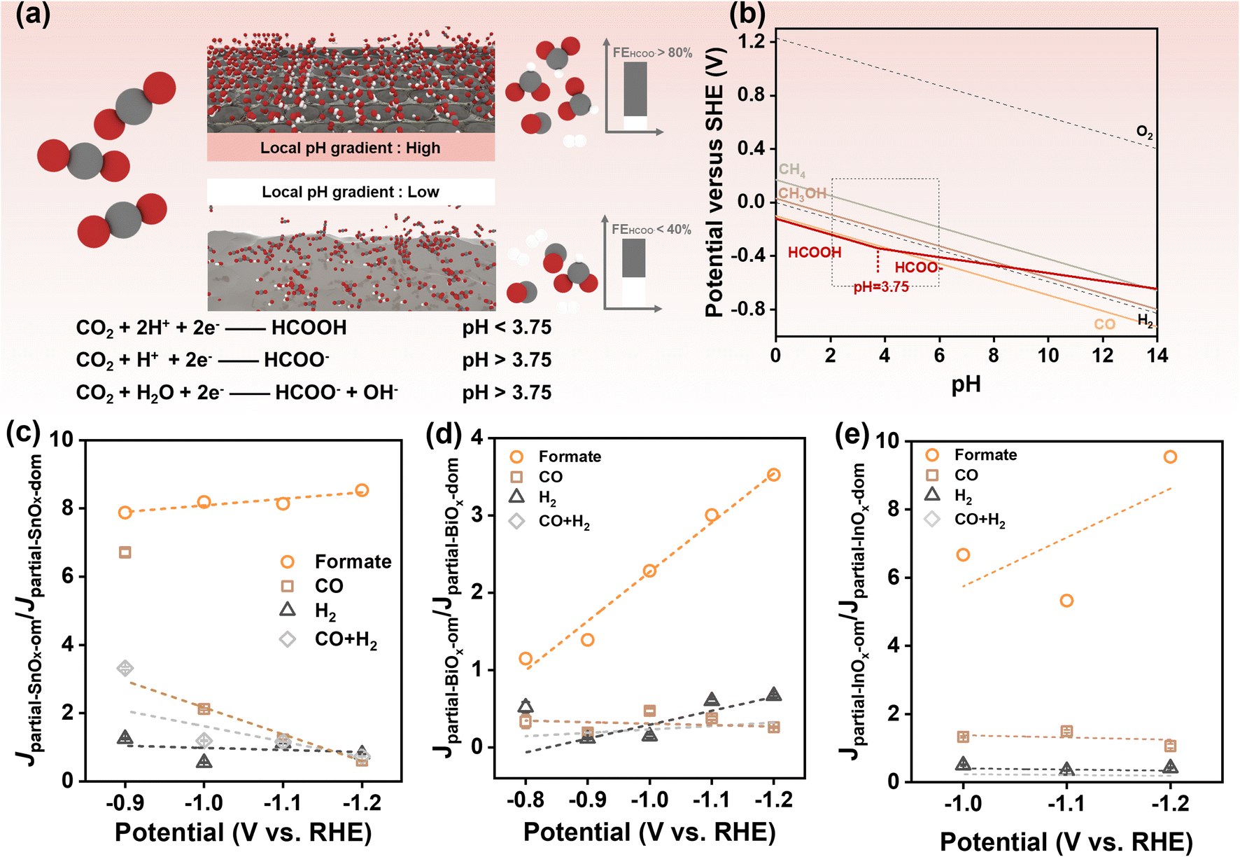 | ||
| Fig. 5 Influence of local pH gradient on selectivity towards formate. (a) Illustration diagram on pH-dependent CO2RR for the production of formate/formic acid; (b) Pourbaix diagrams for CO2RR and water splitting. The construction process is detailed in ESI Note 1;† (c–e) partial current density ratio of ordered and disordered mesoporous catalysts plotting against applied potentials for (c) SnOx, (d) BiOx, and (e) InOx. | ||
Additionally, local diffusion gradients24,25 and the confinement of reactants and intermediates29,31,32 play significant roles in enhancing selectivity during electrochemical processes. In 2006, Prof. Yogesh Surendranath demonstrated the critical contribution of ordered mesoporous structures to selective CO production using Ag/Au inverse opals as an ideal platform.27,28 These mesoporous structures, which share the same surface characteristics, were found to suppress hydrogen evolution reaction (HER) catalysis by a factor of ten.27,28 This effect has been utilized to rationalize the porosity-induced high selectivity observed in CO2 electroreduction.29 Furthermore, the presence of mesopores can extend the residence time of intermediates within the catalyst, thereby improving selectivity.30–32 For example, by precisely controlling the pore widths and depths of a Cu mesoporous electrode, C2 chemical selectivity can be tuned as a result of changes in local pH and the retention time of key intermediates confined within the pores.30 Similar variations in selectivity have also been observed in hierarchical porous and nanoporous Cu electrodes, as well as those with rough surfaces.31,32
In summary, our spectroscopic and electrochemical results indicate that the exclusive exposure of active sites for the formate, enhanced mass transport, and modulated local microenvironments collectively contribute to the exceptional catalytic performance of CO2RR.
3.4 Application of ordered mesoporous catalysts in the flow cell
To assess the potential for practical applications, SnOx-om catalysts were evaluated in a flow cell configuration (Fig. 6). The polarization curves indicate that SnOx-om exhibits significantly higher catalytic activity and selectivity for formate compared to SnOx-dom (Fig. 6a and b). SnOx-om demonstrates an onset potential of less than −0.5 V vs. RHE for CO2RR, which is over 50 mV more positive than that of SnOx-dom. Similar to the H-cell configuration, formate remains the dominant product, while CO, CH4, and H2 are produced as minor products (Fig. S13†). Under potentials ranging from −0.4 to −0.7 V vs. RHE, SnOx-om delivers partial current densities for formate of 13–324 mA cm−2, which is 4 to 7 times higher than the current densities achieved by SnOx-dom (Fig. 6c). Additionally, SnOx-dom shows significantly better selectivity towards formate (Fig. 6a–c), achieving FEs of 71–91%, whereas SnOx-dom has FEs ranging from only 44% to 58% at these potentials. At the optimal potential of −0.65 V vs. RHE, SnOx-om exhibits an FE of 91% for formate at a partial current density of 206 mA cm−2. In stark contrast, SnOx-om manifests an FE of merely 58% at a lower partial current density of 48 mA cm−2 (Fig. 6c). For both catalyst types, the apparent activity and selectivity are improved compared to those observed in the H-cell configuration. This enhancement can likely be attributed to changes in cell configuration and the electrolyte, which transitions from neutral KHCO3 to alkaline KOH. Previous studies have indicated that a higher pH electrolyte results in improved selectivity towards formate, and the three-phase interface facilitates mass transfer.54 Moreover, we found that SnOx-om and SnOx-dom exhibit similar FE dependence on potential for specific products (Fig. 6c), suggesting that both types of catalysts may possess the same active sites but differ in their quantities. The contribution of microenvironmental modulations was further investigated using the FE ratio of the ordered mesoporous catalyst to the disordered counterpart. We observed that the FE ratio for formate increases with a negative shift in potential, while the FE ratios for other products decrease (Fig. 6d). This indicates the presence of local pH gradients, local diffusion gradients, and reactant/intermediate confinement during operation in flow cells, which collectively enhance selectivity towards formate. The EIS analysis of catalysts in a flow cell configuration further confirms the advantages of SnOx-om (Fig. S14 and Table S8†). Both SnOx-om and SnOx-dom samples show improved charge transfer and adsorption/desorption processes at higher applied potentials. At the same optimal potential, SnOx-om demonstrates superior simulated parameters, particularly low RΩ, Cdl, Rp, and moderate CΦ, indicating efficient charge transfer and effective intermediate adsorption/desorption. In comparison to the simulated results from the H-cell, the significant decrease in these parameters is attributable to the change in configuration from the H-cell to the flow cell. This observation reinforces our assertion that the mesoporous structure plays a crucial role in facilitating charge transfer during CO2RR. | ||
| Fig. 6 Electrocatalytic performance of mesoporous SnOx towards CO2 reduction in a flow cell. (a and b) Partial current densities plotting against applied potentials for (a) SnOx-om and (b) SnOx-dom; (c) faradaic efficiency plotting against applied potentials; (d) faradaic efficiency ratio of SnOx-om and SnOx-dom plotting against applied potentials; (e) durability of SnOx-om and SnOx-dom at a −0.65 V vs. RHE. | ||
The durability of the catalysts was assessed using the chronoamperometry method in a flow cell (Fig. 6e). At an applied potential of −0.65 V vs. RHE, SnOx-om achieved a stable current density of 208 mA cm−2, while SnOx-dom only maintained a current density of 86 mA cm−2, representing just 41% of SnOx-om's performance. Additionally, the FE for formate production with SnOx-om was initially as high as 90% in contrast to only 56% FE for SnOx-dom. After 22 hours of electrolysis, SnOx-om still held a current density of 190 mA cm−2 with formate FE of 53%, whereas SnOx-om saw a decline in formate FE to 38% within just 6 hours, despite delivering a much lower current density. The decay rate of SnOx-om was only 1.7 mV h−1, significantly lower than SnOx-dom's 3 mV h−1. Post-catalytic analysis revealed that metallic Sn was produced under the negative potential, as indicated by the increasing XRD peak corresponding to Sn metal and XPS peak for Sn(0) in the catalyst film after 22 hours of electrolysis (Fig. S15a and b†). FESEM images showed that both SnOx-om and SnOx-dom retained their film structure, but the surface became increasingly rough, displaying larger particles (Fig. S15c and d†). The inevitable over-reduction of the catalysts, along with the growth of metallic nanoparticles, likely contributed to the decline in formate FE. The reduced quantity of metallic Sn and the smaller size of metallic nanoparticles for SnOx-om suggest a suppressed self-reduction process compared to SnOx-dom, which aligns with its superior durability. We compared the durability of SnOx-om with both pure and doped Sn-based catalysts previously reported (Table S9†). SnOx-om demonstrates either enhanced durability or competitive durability, combined with significantly improved catalytic activity.
4. Conclusion
In conclusion, we have developed a versatile LLCs-templated method for depositing ordered mesoporous structured electrocatalysts aimed at achieving efficient and selective CO2RR. The feasibility of this method has been demonstrated for Sn, Bi, and In-based catalysts, which exhibited abundant nanopores with an average size of approximately 4.6 nm. These catalysts demonstrated 3 to 8-fold increases in partial current densities (9–25 mA cm−2) compared to disordered mesoporous references and doubled the faradaic efficiency (85–93%) toward formate production. Specifically, ordered mesoporous Sn catalysts delivered a partial current density of 25 mA cm−2 with an FE of 85% for formate generation at a potential of −1.0 V vs. RHE in an H-cell configuration. In a flow cell configuration, these catalysts maintained a current density of up to 206 mA cm−2 for 22 hours, with an exceptional FE of 53–91%, at a potential of −0.65 V vs. RHE. Through spectroscopic and electrochemical analysis, we attributed the outstanding catalytic performance to the exclusive exposure of active sites for the formate, improved mass transport, confinement of reactants and intermediates, and local pH modulation. The approach presented here represents a simple yet effective method for the direct deposition of efficient and selective catalysts onto electrodes. It is not only facile and scalable but also applicable to CO2RR catalysts that are capable of producing other value-added multi-carbon products, such as ethylene and alcohols, as well as catalysts for other energy-intensive reactions. The insights gained into the structure–performance relationship will guide the tailoring of microstructures, contributing a new dimension to the rational design of high-performance CO2RR electrocatalysts.Data availability
The data are available from the corresponding author upon reasonable request.Author contributions
Ashfaq Ahamd: methodology. Chaoran Zhang: investigation, methodology, data curation, formal analysis, validation, writing – original draft. Yichuan Gu: data curation, methodology. Qu Jiang: data curation, methodology. Ziyang Sheng: data curation, validation. Ruohan Feng: data curation, validation, investigation. Sihong Wang: validation, investigation. Haoyue Zhang: data curation, investigation. Qianqing Xu: validation. Zijian Yuan: investigation. Fang Song: conceptualization, funding acquisition, writing – review & editing, supervision.Conflicts of interest
The authors declare no conflict of interests.Acknowledgements
This work was supported by the Shanghai Science and Technology Committee (Grant No. 23ZR1433000), the National Natural Science Foundation of China (Grant No. 22479097), the National High-Level Talent Program for Young Scholars, and the Start-up Fund (F. S.) from Shanghai Jiao Tong University. We also acknowledge the SJTU Instrument Analysis Centre for the measurements.References
- R. I. Masel, Z. Liu, H. Yang, J. J. Kaczur, D. Carrillo, S. Ren, D. Salvatore and C. P. Berlinguette, Nat. Nanotechnol., 2021, 16, 118–128 CrossRef CAS.
- O. S. Bushuyev, P. De Luna, C. T. Dinh, L. Tao, G. Saur, J. van de Lagemaat, S. O. Kelley and E. H. Sargent, Joule, 2018, 2, 825–832 CrossRef CAS.
- Y. Y. Birdja, E. Pérez-Gallent, M. C. Figueiredo, A. J. Göttle, F. Calle-Vallejo and M. T. M. Koper, Nat. Energy, 2019, 4, 732–745 CrossRef CAS.
- S. Biswas, Y. Shingyouchi, M. Ogami, M. Kamiyama, T. Kawawaki and Y. Negishi, EcoEnergy, 2024, 2(3), 400–418 CrossRef CAS.
- M. Grasemann and G. Laurenczy, Energy Environ. Sci., 2012, 5, 8171–8181 RSC.
- O. Yishai, S. N. Lindner, J. Gonzalez de la Cruz, H. Tenenboim and A. Bar-Even, Curr. Opin. Chem. Biol., 2016, 35, 1–9 CrossRef CAS PubMed.
- F. Valentini, V. Kozell, C. Petrucci, A. Marrocchi, Y. Gu, D. Gelman and L. Vaccaro, Energy Environ. Sci., 2019, 12, 2646–2664 RSC.
- E. C. Hann, S. Overa, M. Harland-Dunaway, A. F. Narvaez, D. N. Le, M. L. Orozco-Cárdenas, F. Jiao and R. E. Jinkerson, Nat. Food, 2022, 3, 461–471 CrossRef CAS PubMed.
- F. Li, L. Chen, G. P. Knowles, D. R. MacFarlane and J. Zhang, Angew. Chem., Int. Ed., 2017, 56, 505–509 CrossRef CAS PubMed.
- H. Ge, Z. Gu, P. Han, H. Shen, A. M. Al-Enizi, L. Zhang and G. Zheng, J. Colloid Interface Sci., 2018, 531, 564–569 CrossRef CAS PubMed.
- R. Daiyan, X. Lu, W. H. Saputera, Y. H. Ng and R. Amal, ACS Sustainable Chem. Eng., 2018, 6, 1670–1679 CrossRef CAS.
- S. Liu, X. F. Lu, J. Xiao, X. Wang and X. W. (David) Lou, Angew. Chem., Int. Ed., 2019, 58, 13828–13833 CrossRef CAS PubMed.
- H. Yang, N. Han, J. Deng, J. Wu, Y. Wang, Y. Hu, P. Ding, Y. Li, Y. Li and J. Lu, Adv. Energy Mater., 2018, 8, 1801536 CrossRef.
- L. Xiao, R. Zhou, T. Zhang, X. Wang, R. Zhou, P. J. Cullen and K. (Ken) Ostrikov, Energy Environ. Mater., 2024, 7, e12656 Search PubMed.
- Z. Gao, Y. Gong, Y. Zhu, J. Li, L. Li, Y. Shi, M. Hou, X. J. Gao, Z. Zhang and W. Hu, Nano Res., 2023, 16, 8743–8750 CrossRef CAS.
- X. Huang, J. Song, H. Wu, C. Xie, M. Hua, Y. Hu and B. Han, ChemSusChem, 2020, 13, 6346–6352 CrossRef CAS.
- J. Zhang, T. Fan, P. Huang, X. Lian, Y. Guo, Z. Chen and X. Yi, Adv. Funct. Mater., 2022, 32, 2113075 CrossRef CAS.
- F. Naseem, P. Lu, J. Zeng, Z. Lu, Y. H. Ng, H. Zhao, Y. Du and Z. Yin, ACS Nano, 2020, 14, 7734–7759 CrossRef CAS PubMed.
- C. Jia, Y. Zhao, S. Song, Q. Sun, Q. Meyer, S. Liu, Y. Shen and C. Zhao, Adv. Energy Mater., 2023, 13, 2302007 CrossRef CAS.
- C. Chen, X. Yan, Y. Wu, S. Liu, X. Zhang, X. Sun, Q. Zhu, H. Wu and B. Han, Angew. Chem., Int. Ed., 2022, 61, e202202607 CrossRef CAS.
- J. Choi, J. Kim, P. Wagner, J. Na, G. G. Wallace, D. L. Officer and Y. Yamauchi, J. Mater. Chem. A, 2020, 8, 14966–14974 RSC.
- Q. Lu, J. Rosen, Y. Zhou, G. S. Hutchings, Y. C. Kimmel, J. G. Chen and F. Jiao, Nat. Commun., 2014, 5, 3242 CrossRef PubMed.
- W. Zhang, J. He, S. Liu, W. Niu, P. Liu, Y. Zhao, F. Pang, W. Xi, M. Chen, W. Zhang, S.-S. Pang and Y. Ding, Nanoscale, 2018, 10, 8372–8376 RSC.
- M. N. Hossain, Z. Liu, J. Wen and A. Chen, Appl. Catal., B, 2018, 236, 483–489 CrossRef CAS.
- G. Yang, Y. Kuwahara, K. Mori, C. Louis and H. Yamashita, Nano Res., 2023, 16, 4515–4523 CrossRef CAS.
- G. Liu, Z. Li, J. Shi, K. Sun, Y. Ji, Z. Wang, Y. Qiu, Y. Liu, Z. Wang and P. Hu, Appl. Catal., B, 2020, 260, 118134 CrossRef CAS.
- A. S. Hall, Y. Yoon, A. Wuttig and Y. Surendranath, J. Am. Chem. Soc., 2015, 137, 14834–14837 CrossRef CAS.
- Y. Yoon, A. S. Hall and Y. Surendranath, Angew. Chem., Int. Ed., 2016, 55, 15282–15286 CrossRef CAS PubMed.
- C. Hu, S. Bai, L. Gao, S. Liang, J. Yang, S.-D. Cheng, S.-B. Mi and J. Qiu, ACS Catal., 2019, 9, 11579–11588 CrossRef CAS.
- S. Sen, D. Liu and G. T. R. Palmore, ACS Catal., 2014, 4, 3091–3095 CrossRef CAS.
- K. D. Yang, W. R. Ko, J. H. Lee, S. J. Kim, H. Lee, M. H. Lee and K. T. Nam, Angew. Chem., Int. Ed., 2017, 56, 796–800 CrossRef CAS.
- A. Dutta, M. Rahaman, M. Mohos, A. Zanetti and P. Broekmann, ACS Catal., 2017, 7, 5431–5437 CrossRef CAS.
- G. S. Attard, J. M. Corker, C. G. Göltner, S. Henke and R. H. Templer, Angew. Chem., Int. Ed. Engl., 1997, 36, 1315–1317 CrossRef CAS.
- G. S. Attard, P. N. Bartlett, N. R. B. Coleman, J. M. Elliott, J. R. Owen and J. H. Wang, Science, 1997, 278, 838–840 CrossRef CAS.
- H. Lim, K. Kani, J. Henzie, T. Nagaura, A. S. Nugraha, M. Iqbal, Y. S. Ok, M. S. A. Hossain, Y. Bando, K. C. W. Wu, H.-J. Kim, A. E. Rowan, J. Na and Y. Yamauchi, Nat. Protoc., 2020, 15, 2980–3008 CrossRef.
- J. Liu, Z. Liu, H. Wang, B. Liu, N. Zhao, C. Zhong and W. Hu, Adv. Funct. Mater., 2022, 32, 2110702 CrossRef CAS.
- P. A. Wieser, D. Moser, B. Gollas and H. Amenitsch, ACS Appl. Mater. Interfaces, 2023, 15, 47604–47614 CrossRef CAS.
- A. A. Farmani and F. Nasirpouri, J. Mater. Chem. A, 2020, 8, 24782–24799 RSC.
- C. Zhang, H. Yang, T. Sun, N. Shan, J. Chen, L. Xu and Y. Yan, J. Power Sources, 2014, 245, 579–582 CrossRef CAS.
- V. Malgras, H. Ataee-Esfahani, H. Wang, B. Jiang, C. Li, K. C.-W. Wu, J. H. Kim and Y. Yamauchi, Adv. Mater., 2016, 28, 993–1010 CrossRef CAS.
- J. Dong, X. Mi, T. Sun, Y. Zhang, W. Jiang, F. Li, J. Chen and L. Xu, Nanoscale, 2022, 14, 9104–9111 RSC.
- Y. Wu, L. Ma, Z. Song, S. Dong, Z. Guo, J. Wang and Y. Zhou, Carbon Neutrality, 2023, 2, 1 CrossRef CAS.
- W. Sugimoto, S. Makino, R. Mukai, Y. Tatsumi, K. Fukuda, Y. Takasu and Y. Yamauchi, J. Power Sources, 2012, 204, 244–248 CrossRef CAS.
- J. Hu, X. Xiong, W. Guan and C. Tan, ACS Appl. Mater. Interfaces, 2022, 14, 55249–55263 CrossRef CAS PubMed.
- Y. Saadat, O. Q. Imran, C. O. Osuji and R. Foudazi, J. Mater. Chem. A, 2021, 9, 21607–21658 RSC.
- M. F. Baruch, J. E. I. Pander, J. L. White and A. B. Bocarsly, ACS Catal., 2015, 5, 3148–3156 CrossRef CAS.
- J. Wu, X. Bai, Z. Ren, S. Du, Z. Song, L. Zhao, B. Liu, G. Wang and H. Fu, Nano Res., 2021, 14, 1053–1060 CrossRef CAS.
- X. Wei, Z. Li, H. Jang, Z. Wang, X. Zhao, Y. Chen, X. Wang, M. G. Kim, X. Liu and Q. Qin, Small, 2024, 20, 2311136 CrossRef CAS.
- W. Cheng, X. Xu, Q. Liao, G. Yao, C. Zhang and H. Li, Chem. Eng. J., 2024, 480, 147922 CrossRef CAS.
- F. He, M. Hou, F. Zhu, D. Liu, H. Zhang, F. Yu, Y. Zhou, Y. Ding, M. Liu and Y. Chen, Adv. Energy Mater., 2022, 12, 2202175 CrossRef CAS.
- K. U. Hansen, L. H. Cherniack and F. Jiao, ACS Energy Lett., 2022, 7, 4504–4511 CrossRef CAS.
- T. H. Wan, M. Saccoccio, C. Chen and F. Ciucci, Electrochim. Acta, 2015, 184, 483–499 CrossRef CAS.
- N. Han, P. Ding, L. He, Y. Li and Y. Li, Adv. Energy Mater., 2020, 10, 1902338 CrossRef CAS.
- A. S. Varela, Curr. Opin. Green Sustainable Chem., 2020, 26, 100371 CrossRef.
Footnotes |
| † Electronic supplementary information (ESI) available: Additional materials characterization, Fourier-transformed infrared spectroscopy of lyotropic precursor and SnOx-om samples, TEM images of SnOx-dom, BiOx-om and InOx-om, total current density and faradaic efficiency of the main CO2RR products for SnOx-om, SnOx-dom, BiOx-om, BiOx-dom, InOx-om, InOx-dom and electrochemical impedance spectra analysis. See DOI: https://doi.org/10.1039/d4ta08622h |
| ‡ The authors contributed equally to this work. |
| This journal is © The Royal Society of Chemistry 2025 |