
 Open Access Article
 This Open Access Article is licensed under a
 Creative Commons Attribution 3.0 Unported Licence
Lithium and oxygen engineered SiO0.5 materials for high performance lithium storage materials†
Ji Young
Kim
,
Dong Jae
Chung
,
Tae Rim
Lee
,
Donghan
Youn
and
Hansu
Kim
 *
*
Department of Energy Engineering, Hanyang University, 222 Wangsimni-ro, Seongdong-gu, Seoul 04763, Republic of Korea. E-mail: khansu@hanyang.ac.kr
First published on 13th February 2025
Abstract
Silicon monoxide (SiO) is one of the most promising post-graphite anode materials for lithium-ion batteries. Prelithiation of SiO has been proposed as a potential method to improve its initial coulombic efficiency (ICE), which is a persistent challenge for SiO. However, pre-lithiation can decrease the capacity of SiO due to the formation of lithium silicate phases. To address this issue, we developed a strategy to improve the ICE and reversible capacity of SiO through lithium and oxygen engineering. Prelithiated Si-enriched SiO0.5 prepared by high-energy mechanical milling of Si and SiO with lithiation followed by LiH treatment, exhibited a capacity of 2093 mA h g−1 with an ICE of 88.1%, significantly surpassing the performance of both pristine and prelithiated SiO. While increasing the Si content may typically result in poor capacity retention, the unique porous structure formed by the Si and lithium silicate phases in this study mitigated this effect, ensuring capacity retention over 300 cycles by alleviating the expansion of Si during the lithiation/delithiation process.
1. Introduction
The increasing demand for higher energy density in lithium-ion batteries (LIBs) has led to the consideration of silicon monoxide (SiO) as one of the most promising alternatives to the widely used graphite anode materials.1,2 SiO offers a lower volume expansion (∼160%) compared to silicon (∼300%) and a higher reversible capacity (∼1700 mA h g−1) than graphite (372 mA h g−1).3,4 However, persistent issues, such as low initial coulombic efficiency (ICE) and poor cycle stability, have hindered the full commercialization of SiO as an anode material for LIBs.5–7 The low ICE of SiO is attributed to the initial irreversible electrochemical reaction between Li ions and amorphous SiO, which consumes Li ions from the cathode material, thereby lowering the practical energy density of LIBs.8–10 Prelithiation is one of the most effective ways to address this issue, achieved by externally supplying lithium ions to either the SiO anode material or the SiO electrode. In the case of electrode-level prelithiation, the ICE of the prelithiated SiO anode has been shown to exceed 100%.11,12 However, the precise control of lithiation and the additional facilities required for electrode-level prelithiation present challenges for its commercial viability. At the material level, various lithium sources, such as lithium compounds, stabilized lithium metal powders, and molten lithium, have been explored as sacrificial materials to supply lithium ions to SiO, some of which have been proven to improve the ICE of SiO.8,13–15 However, most lithium sources used for prelithiation, especially metallic lithium, pose safety concerns due to their sensitivity to moisture and oxygen, which can lead to fires.13,14 Recently, Chung et al. suggested the Li-metal-free prelithiation of SiO with lithium hydride (LiH), which is more stable under ambient conditions than Li metal due to the strong ionic bond between Li and H. This approach improved the ICE to 92.7% and resulted in highly stable cycle performance.16,17 This promising result was attributed to the optimization of the topological arrangement of the active Si phase and Li2SiO3 buffer phase.17 However, the prelithiated SiO with LiH showed a specific capacity of 1164 mA h g−1, lower than that of carbon-coated SiO (1760 mA h g−1). It is well established that Si-rich SiOx (0 < x < 1) materials offer higher capacities than SiO. Cao et al. reported that Si-rich SiOx (0 < x < 0.37) prepared by exposing ball-milled Si powder to air, achieved a high volumetric capacity of 1800 Ah L−1 and an ICE of 70%, outperforming pristine SiO (1400 Ah L−1 and 55%, respectively).18 Similar Si-rich SiOx materials can be prepared via high-energy mechanical milling of Si and SiO2 particles or Si and SiO particles.19 The resulting Si-rich SiOx composite materials showed reversible capacities of 1744 mA h g−1 (for the Si/SiO2 composite) and 2157 mA h g−1 (for the Si/SiO composite), both of which surpass the capacity of SiO (1522 mA h g−1).16,17,20–22 These reports on Si-rich SiOx inspired us to propose that the prelithiation of Si-rich SiOx could further increase the capacity of prelithiated SiO. However, the possibility that a higher Si phase content in Si-rich SiOx materials could accelerate electrode degradation due to the significant volume changes of the Si phase during cycling cannot be overlooked. To solve this adverse effect resulting from the use of Si-rich SiOx instead of SiO, we selected ball-milled Si/SiOx composites as the starting materials for prelithiated Si-rich SiOx which offers higher capacity than SiO while maintaining stable long-term cycle performance. We anticipated that the free void spaces generated in Si-rich SiOx during ball milling could play a key role in accommodating the volume expansion of the electrode, thereby maintaining its mechanical integrity. To evaluate this hypothesis, we prepared porous prelithiated Si-rich SiOx anode materials using high-energy mechanical milling (HEMM) of Si and SiO particles, followed by dehydrogenation-driven prelithiation with LiH. The materials prepared by lithium and oxygen engineering were porous nanocomposites consisting of dual-sized crystalline Si phases as the Li-active phase and two types of lithium silicate phases, which serve as Li-inactive buffers. The resulting Si/Li2Si2O5/Li2SiO3 composite, with abundant nanopores, showed significantly improved anode performance, delivering a high capacity of 2093 mA h g−1 with an ICE of 88.1% and stable capacity retention over 300 cycles.2. Experimental
2.1. Material preparation
Amorphous SiO powder (average particle size ∼5 μm, OSAKA Titanium Technologies Co., Ltd., Japan) and crystalline Si powder (particle size 1–5 μm, Alfa Aesar, USA) were mixed and ball-milled using a vibratory mill in an Ar atmosphere for 18 h at 800 rpm. The ball-powder ratio was set to 20![[thin space (1/6-em)]](https://www.rsc.org/images/entities/char_2009.gif) :1 (big ball:small ball = 2:1). The obtained powder was then mixed with LiH (>97%, Alfa Aesar, USA) at a Li/Si ratio of 0.25 (molar ratio) in an Ar-filled glove box. This mixture was heated at 750 °C for 6 h at a ramp rate of 10 °C min−1 under an Ar atmosphere in alumina crucibles.
:1 (big ball:small ball = 2:1). The obtained powder was then mixed with LiH (>97%, Alfa Aesar, USA) at a Li/Si ratio of 0.25 (molar ratio) in an Ar-filled glove box. This mixture was heated at 750 °C for 6 h at a ramp rate of 10 °C min−1 under an Ar atmosphere in alumina crucibles.
2.2. Material characterization
X-ray diffraction (XRD; D8 ADVANCE, Bruker, USA) patterns of pristine SiO, Si, SSO composites and LSSO powders were obtained using Cu Ka radiation (1.5418 A). A Raman spectrometer (DXR-3xi, Thermo Fisher Scientific, USA) was used to obtain the Raman spectra of the same samples using a 532 nm laser. To investigate the chemical state of the materials, 29Si magic angle spinning nuclear magnetic resonance (29Si MAS NMR; AVANCE III HD 400 MHz NMR, Bruker, Germany) was performed. The cross-sections of the particles were investigated using FIB (Scios, FEI, USA), FE-SEM (Scios, FEI, USA), and EDS (Scios, Tersizer 2000, Malvern). The specific surface areas of SiO, Si, SSO-1 and LSSO were analyzed using BET methods after conducting standard nitrogen adsorption and desorption isotherm measurements at 77 K with an analyzer (3 Flex, Micrometrics, Canada). The microstructures of SSO-1 and LSSO were analyzed using HR-TEM (ARM-200F, JEOL, Akishima, Japan), HAADF-STEM (ARM-200F, JEOL, Akishima, Japan), and EDS (Aztec, Oxford, UK).2.3. Electrochemical characterization
The electrode slurry of each sample was prepared with 80 wt% active materials, 10 wt% conductive agent (Super-P, TIMCAL), and 10 wt% binder (PAA; polyacrylic acid, 2 wt% in H2O, Sigma Aldrich) on copper foil. Coin-type half cells (CR2032, Wellcos Co) of each sample were assembled with a separator (PE; poly ethylene, F16BME, Tonen), 1 M LiPF6 in a solvent mixture of ethylene carbonate (EC)/ethyl methyl carbonate (EMC)/diethyl carbonate (DEC) (2:2:5, v/v/v, Panax Etec Co. Ltd) electrolyte with 10 wt% fluoroethylene carbonate (FEC) additive, and lithium metal foil (200 μm, Honjo Metal) as a counter electrode in an Ar-filled glove box. Electrochemical tests were conducted using a battery cycle system (CTS-LAB, BasyTec). The half-cells of each sample were galvanostatically discharged in constant current–constant voltage (CC–CV) mode and charged in CC mode, within a voltage window between 0.01 and 1.5 V (vs. Li/Li+). The current density was 100 mA g−1 for the initial three formation cycles and 500 mA g−1 for the subsequent 300 cycles. CV mode was performed at 10 mV up to a current density of 10 mA g−1.
2.4. Ex situ electrode characterization
Cross-sectional images of the SSO-1 and LSSO electrodes were obtained using SEM (JSM-700F, JEOL, Japan). The coin-type half-cells employing SSO-1 and LSSO electrodes were disassembled in an Ar-filled glove box after initial lithiation, after the first cycle, and after 300 cycles. The obtained electrodes were rinsed with dimethyl carbonate (DMC; 99.9%, Sigma-Aldrich, USA) and Ar milled with a cross-section polisher (JEOL, Japan). The microstructures of the cycled electrodes of SSO-1 and LSSO were investigated using HR-TEM (ARM-200F, JEOL, Akishima, Japan), HAADF-STEM (ARM-200F, JEOL, Akishima, Japan), and EDS (Aztec, Oxford, UK).2.5. Electrochemical coin-type full cell test
The negative electrodes of full cells were fabricated by coating slurries containing 77.25 wt% graphite (commercial vendor) and 18 wt% SSO-1 and LSSO materials as active materials with 1.25 wt% conducting agent (Super-C, TIMCAL), 2.0 wt% styrene-butadiene rubber (SBR; BM-400B, Zeon, Japan) and 1.5 wt% sodium carboxymethyl cellulose (CMC; Dai-ichi Kogyo Seijaku Co. LTD., Japan) as a binder onto Cu foil. The positive electrodes of full cells were fabricated by coating a slurry composed of LiNi0.88Co0.06Mn0.06O2 of 94 wt% (commercial vendor) as an active material, 3 wt% conducting agent (Super-C, TIMCAL) and PVdF binder (polyvinylidene fluoride, KF1100, Kureha). The loading levels of the prepared positive electrodes were 17.6 mg cm−2. Note that the N/P ratio (negative to positive electrode areal capacity ratio) was set to 1.05. The coin type full cells (CR2032, Wellcos Co.) were assembled with the as-prepared negative electrodes, positive electrodes, polyethylene separator (PE; F16BME, Tonen), and 1.0 M LiPF6 in EC/EMC/DEC (2:2:5, v/v/v. Panax Etec Co. Ltd.) with 10 wt% additional FEC in an Ar filled glove box. The full cells were electrochemically cycled with an initial 3 cycles at 0.35 mA cm−2 (0.1 C-rate) between 2.7 and 4.2 V in constant current–constant voltage (CC–CV) mode, followed by 300 cycles at 3.5 mA cm−2 (1 C-rate) for the subsequent 100 cycles using a battery cycle system (CTS-LAB, Basytec).
3 Results and discussion
Fig. 1 shows a schematic of the synthesis for the porous prelithiated Si-rich silicon oxide composite (LSSO). To prepare LSSO, Si/SiO composites (SSO) were first produced by high-energy mechanical milling (HEMM) of Si and SiO micron-sized particles, the starting materials, using four different Si-to-SiO ratios (Si/SiO ratio): 4, 2.03, 1, and 0.25. These composites are denoted as SSO-4, SSO-2.03, SSO-1, and SSO-0.25, respectively. The Si/SiO composites were then subjected to dehydrogenation-driven prelithiation using LiH.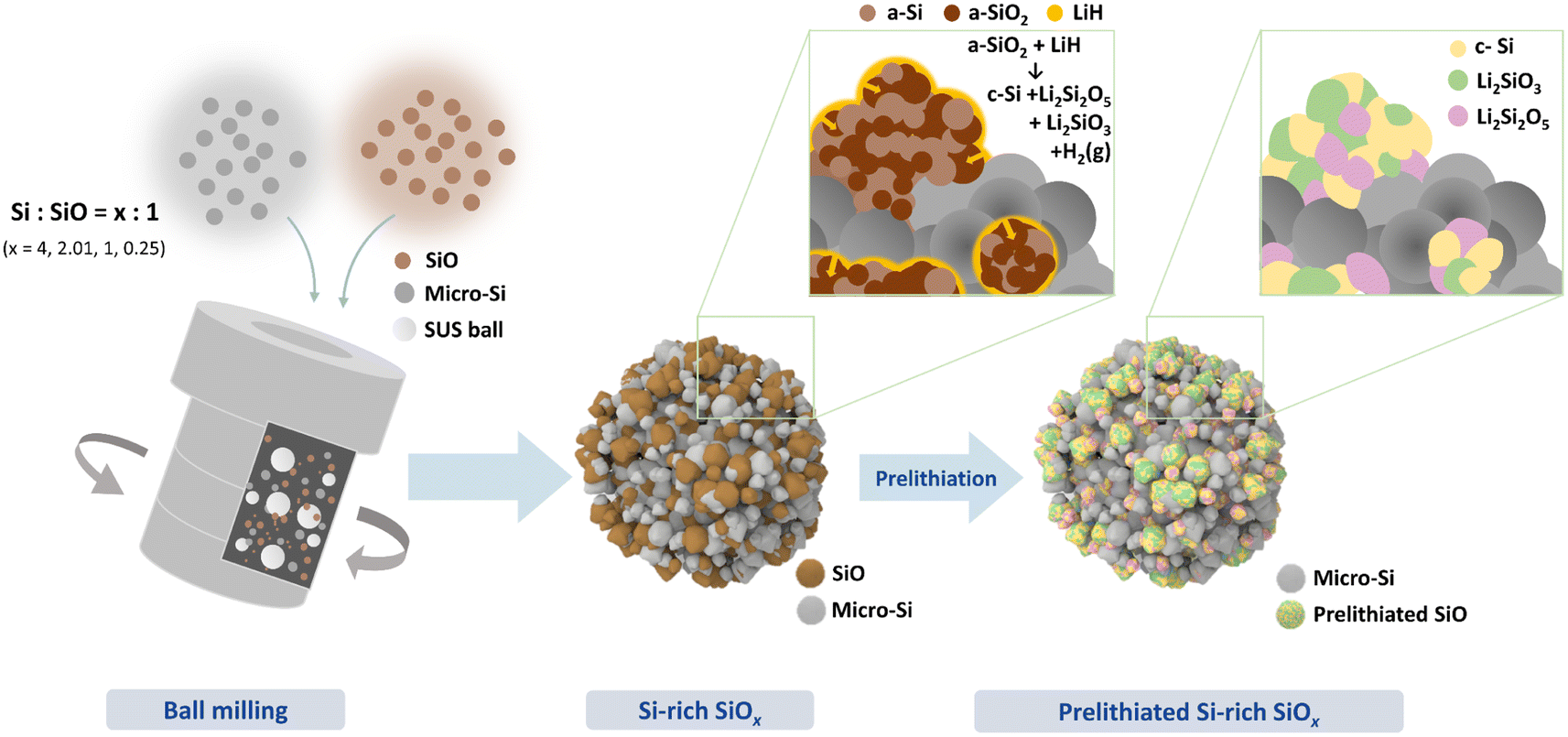 | ||
| Fig. 1 Schematic illustration of the prelithiated Si-rich SiOx composite. | ||
Fig. 2a shows the X-ray diffraction (XRD) patterns of the synthesized SSO composites, along with the micron-sized Si particles and SiO particles used in the composites. The XRD patterns indicate that the Si particles exhibit crystallinity, while the SiO particles are amorphous. The Bragg peaks corresponding to the crystalline Si phase in the SSO composites broadened after high-energy mechanical milling due to the inhomogeneous strain induced during the milling process.23 The broad peak at 23° in the XRD patterns of the SSO composites corresponds to amorphous SiO. After prelithiation of the SSO composites with LiH, the XRD pattern of the LSSO material showed the disappearance of the Bragg peak for amorphous SiO, and the emergence of new Bragg peaks corresponding to the Li2Si2O5 and Li2SiO3 phases. These lithium silicate phases were formed by the prelithiation of SiO with LiH. 16,17Fig. 2b shows the Raman spectra of the SSO-1, LSSO, micro-Si, and amorphous SiO particles. Two different Raman bands are observed in the Raman spectrum of SSO-1: a broad band from 400 to 480 cm−1, attributed to the amorphous Si phase (a-Si) from the SiO particles, and a sharp band at 520 cm−1 corresponding to the crystalline Si phase (c-Si) from the Si particles. According to the random mixture model of SiO, SiO consists of a-Si and amorphous SiO2 (a-SiO2) in an equal molar ratio.16,17,24 These results indicate that SSO-1 particles maintain both the physical properties of both Si and SiO even after high-energy ball milling. By comparing Raman spectra of SSO-1 and LSSO, we observed the phase transition before and after prelithiation. The Raman bands corresponding to a-SiO2 and a-Si disappeared, while only the distinctive Raman band of the transverse optical mode of c-Si was detected at 520 cm−1. This indicates that the amorphous SiO reacted with Li released from dehydrogenated LiH, forming c-Si and lithium silicate phases during the heat treatment.16,17,25 These results are consistent with previous studies on the prelithiation of SiO using LiH. To further understand the phase transformation of SSO-1 during prelithiation, 29Si magic angle spinning nuclear magnetic resonance (29Si-MAS-NMR) spectroscopy was performed, as shown in Fig. 2c. The 29Si NMR spectrum of SSO-1 exhibits two chemical shifts at −75 ppm and −108 ppm corresponding to Si (−70 ppm for a-Si and −81 ppm for micro-Si) and a-SiO2, respectively. These results are in good agreement with the Raman spectra of the SSO-1 material. After prelithiation, the chemical shifts associated with a-Si and a-SiO2 disappeared, and the distinctive chemical shifts corresponding to lithium silicates (−92 ppm for Li2Si2O5 and −75 ppm for Li2SiO3) and c-Si (−83 ppm) appeared. These results align well with the XRD pattern of the LSSO material. Notably, the silicon phase did not react with lithium from LiH to form a Li–Si alloy phase. These results clearly show that the Si particles in SSO-1 remained chemically unreacted throughout the process, whereas the amorphous SiO particles reacted with Li to form lithium silicate phases and c-Si.
 | ||
| Fig. 2 (a) XRD pattern of Si, SiO, SSO-4, SSO-2.03, SSO-1, SSO-0.25 and LSSO, (b) Raman spectra of SSO-1 and LSSO and (c) 29Si MAS NMR spectra of Si, SiO, prelithiated SiO, SSO-1, and LSSO. | ||
Fig. 3a and b show the electrochemical performance of the prepared SSO composite electrodes for the first cycle. The SSO composite electrodes exhibited initial reversible capacities of 3157 mA h g−1, 2753 mA h g−1, 2129 mA h g−1, and 1840 mA h g−1 for Si/SiO ratios of 4, 2.03, 1, and 0.25, respectively. The ICEs of the SSO composite electrodes were 80.5% (SSO-4), 78.4% (SSO-2.03), 69.7% (SSO-1), and 59.4% (SSO-0.25). Both the discharge capacity and the ICE of the SSO composite electrodes were higher than those of the pristine SiO electrode, which delivered an initial reversible capacity of 1076 mA h g−1 with an ICE of 44.8% (Fig. S1†). These results also show that the ICE and discharge capacity of the SSO composite electrodes increase with higher Si content. Among the SSO composites, SSO-1 demonstrated optimal performance with a discharge capacity exceeding 2000 mA h g−1 while maintaining stable cycle performance. Based on these results, SSO-1 was chosen for prelithiation to further improve the electrochemical performance. The LSSO, the prelithiated form of SSO-1, electrode delivered a discharge (lithiation) capacity of 2378 mA h g−1 and a charge (delithiation) capacity of 2093 mA h g−1 corresponding to an ICE of 88.1%. This represents a substantial 19.8% improvement compared to the ICE of the SSO electrode with the same Si content (69.7%). The increase in ICE is attributed to the pre-emptive formation of irreversible phases during prelithiation with LiH, which reduces lithium consumption during the initial cycle. The differential capacity plots (DCP) of the SSO-4, SSO-2.03, SSO-1, SSO-0.25, and LSSO electrodes for the initial cycle show a DCP peak at approximately 200 mV (vs. Li/Li+) and a peak below 100 mV (vs. Li/Li+) upon lithiation. (Fig. S2†) The peak at 200 mV is associated with the irreversible reaction of a-SiO2 with Li, forming lithium silicates, while the peak below 100 mV corresponds to the alloying reaction of the Si phase. As the portion of SiO in the SSO composite increases, the peaks between 460 and 200 mV (vs. Li/Li+) become more pronounced, showing the maximum intensity in the SSO-0.25 composite. The disappearance of these peaks in the DCPs during the second cycle suggests that these peaks reflect the irreversible electrochemical reaction of SiO in the first cycle. In contrast, the LSSO electrode shows a more negative and sharper DCP peak at 70 mV (vs. Li/Li+), suggesting that the a-SiO2 in SSO-1 effectively reacted with LiH during prelithiation, eliminating the significant peak at approximately 200 mV (vs. Li/Li+). Upon delithiation, the SSO electrodes showed a similar tendency. The peak intensity around 450 mV, corresponding to the de-alloying reaction of crystalline Li3.75Si (c-Li3.75Si), increased with an increase of Si content in the composite. Notable differences were observed between the SSO-1 and LSSO electrode. The SSO electrode shows two peaks at approximately 300 and 450 mV (vs. Li/Li+) corresponding to lithium removal from the amorphous LixSi alloy and c-Li3.75Si (the richest Li–Si phase), respectively. These results show that the SSO-1 electrode has the electrochemical features of both micro-Si and SiO materials; however, after prelithiation, the lithium storage mechanism of the LSSO electrode changes due to the phase transition of SSO-1 into Li-active (Si phase) and Li-inactive phases (lithium silicate phases). Fig. 3c shows the cycle performances of the SSO-1 and LSSO electrodes over 300 cycles at a rate of 500 mA g−1, following three formation cycles at a rate of 100 mA g−1. The SSO composite electrode with the highest Si content (SSO-4) showed the highest specific capacity but experienced the fastest capacity fading within the initial 50 cycles, whereas the SSO and SSO-0.25 electrodes showed stable cycle performance with lower discharge capacities. These results indicate a trade-off relationship between specific capacity and cycle performance of the SSO-1 composite electrodes. Prelithiation was expected to address this trade-off relationship in SSO composite anode materials and improve the ICE of the SSO composite electrodes. After 300 cycles, the SSO-1 electrode maintained a capacity of 940 mA h g−1 (44.2% retention), while the LSSO electrode delivered 1070 mA h g−1 with a capacity retention of 51.1%. The superior cycle performance of the LSSO electrode compared with the SSO-1 electrode can be attributed to the Li-inactive lithium silicate phase, which suppressed the expansion of the electrode and maintained its integrity during the charge/discharge process. Although the SSO-1 electrode did not perform as well as LSSO, it still showed improved cycle performance compared to pristine Si and SiO electrodes, which exhibited rapid capacity fading with capacity retention of 16.5% and 33.6% of the initial capacity, respectively, after 300 cycles (Fig. S1, ESI†). These results revealed that the Li–inactive lithium silicate buffer phase was not the only factor contributing to the improved cycling performance of the LSSO electrode. The free voids in the SSO composite particles created through high-energy ball milling also played a role in relieving the mechanical stresses generated in the electrode during cycling. It is widely recognized that a porous microstructure with large surface areas can accommodate volume changes in the Si phase during cycling and shorten the diffusion path for Li ions, thereby facilitating Li ion transport in Si-based anode materials.26–28Fig. 3d shows the rate capability of SSO-1 and LSSO electrodes at current densities ranging from 0.1 to 5 A g−1 after three formation cycles at 100 mA g−1. At a high current density of 5.0 A g−1, the SSO and LSSO electrodes maintained 65.7% and 77.6% of the capacity retention obtained at a rate of 0.1 A g−1, respectively. The materials showed excellent rate capabilities, largely due to their porous structures, which facilitate Li ion transport within the electrode.29
 | ||
| Fig. 3 (a) Voltage profile for first cycle in a voltage window of 0.01–1.5 V vs. Li/Li+ at a current density of 100 mA g−1, (b) electrochemical properties, (c) cycle performance of SSO-4, SSO-2.03, SSO-1, SSO-0.25 and LSSO electrodes and (d) voltage profiles of SSO-1 and LSSO electrodes at different current densities. | ||
Fig. 4a and c show scanning electron microscopy (SEM) images of the SSO-1 and LSSO materials. The top-view SEM images show that both SSO-1 and LSSO have rough surfaces compared to the starting materials, Si and SiO particles (Fig. 4a and c; see also S3†). Cross-sectional observation by focused ion beam-scanning electron microscopy (FIB-SEM) revealed the presence of internal pores within the particles (Fig. 4b–d and see also S4†). These pores were generated during the high-energy ball milling process, where mechanical impact causes the fracture of primary particles, leading to particle refinement.30,31 These refined particles then aggregate into secondary particles through cold welding during the continuous milling process, simultaneously creating free voids within the secondary structures due to imperfect particle packing. More importantly, FIB-SEM revealed two distinct domains, differentiated by brightness levels: Si and SiO. To investigate the microstructure of SSO-1 and LSSO particles in more detail, high-angle annular dark-field scanning transmission microscopy (HAADF-STEM), energy dispersive X-ray spectroscopy (EDS), selected area electron diffraction (SAED), and high-resolution transmission electron microscopy (HR-TEM) were conducted. Fig. 4e and g show HAADF-STEM images of the SSO-1 and LSSO particles, both of which exhibit porous structures, with voids appearing as black areas, similar to the FIB-SEM images. Combined with EDS analysis, the particles can be classified into two regions: Si and O coexisting domains and Si-rich domains, both of which have reduced sizes compared to the starting materials (Fig. 4e–f for SSO-1 and 4g–h for LSSO). In the Si and O coexisting domains, a microstructural difference was observed between SSO-1 and LSSO. There is no Z-contrast observed in SSO-1, whereas there is a distinguishable Z-contrast in LSSO. To further investigate the microstructural difference, the coexisting domains were magnified up to 800 K (Fig. 4i and k). The HAADF-STEM images of SSO-1 and LSSO at 800 K magnification, along with the corresponding element mapping from EDS analysis revealed that there are two distinct Si-rich and O-rich domains in LSSO, whereas SSO-1 showed a uniform distribution of Si and O (Fig. 4i and j for SSO-1 and Fig. 4k and l for LSSO). SAED patterns showed the presence of only the crystalline c-Si phase (d022 = 1.90 Å) in SSO-1, while LSSO showed three different crystalline phases: Si (d111 = 3.11 Å), Li2Si2O5 (d110 = 5.39 Å) and Li2SiO3 (d111 = 3.30 Å) (Fig. 4m for SSO-1 and n for LSSO; see also Fig. S5†). HR-TEM observations are in good agreement with the XRD and NMR analyses. Based on these phase analysis results, the areas with uniform Si and O distributions were assigned to SiO, and the Si- and O-rich domains were assigned to a mixture of c-Si and lithium silicate (Li2SiO3 and Li2Si2O5) phases (Fig. 4j and l). To further understand the pore structure of SSO-1 and LSSO observed through FIB-SEM and STEM analysis, Brunauer–Emmett–Teller (BET) analysis was performed (Fig. 4o). The SSO-1 material possessed a BET surface area of 16.73 m2 g−1, which is larger than those of the starting materials Si (8.05 m2 g−1) and SiO (2.62 m2 g−1). The pore volume of SSO-1, estimated at 0.06699 cm3 g−1 using the BJH method, was also larger than those of the starting materials (0.02616 cm3 g−1 for Si particles and 0.00718 cm3 g−1 for SiO particles) (Fig. S5, ESI†). This suggests that ball milling increases both the surface area and pore volume of the material.25,32 The surface area and pore volume of the LSSO material after prelithiation of SSO-1 were 9.52 m2 g−1 and 0.02564 cm3 g−1, respectively. This reduction in surface area and pore volume in LSSO materials might be closely related to the prelithiation process. Similar results were reported by Alanoina et al., where prelithiation using lithium stearate filled pores and repaired surface cracks, as verified by TEM and BET analyses.33
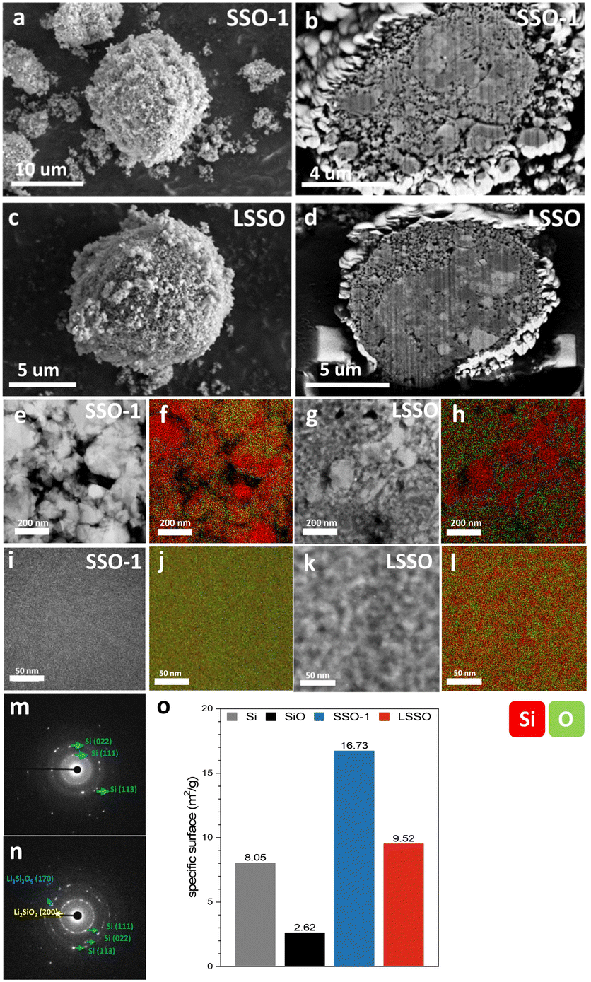 | ||
| Fig. 4 (a) Top view SEM image and (b) cross-sectional SEM image of SSO-1. (c) Top view SEM image and (d) cross-sectional SEM image of LSSO. (e–h) HAADF-STEM image (250 K), STEM/EDS elemental mapping of Si and O and SAED patterns of SSO-1 and LSSO. (i–l) HAADF-STEM image (800 K), STEM/EDS elemental mapping of Si and O and SAED patterns of SSO-1 and LSSO. Red and green marks in STEM/EDS represent Si and O, respectively. (m and n) SAED patterns of SSO-1 and LSSO. (o) Brunauer–Emmett–Teller (BET) surface areas of Si, SiO, SSO-1 and LSSO. | ||
Fig. 5a shows the thicknesses of the SSO-1 and LSSO electrodes in the pristine state after lithiation (discharging to 10 mV vs. Li/Li+), after 1 cycle, and after 300 cycles. The thickness change after the lithiation of the LSSO electrode was 95%, significantly lower than the expansion observed in the SSO-1 electrode (130%) under the same conditions (Fig. 5b). During the initial lithiation, the presence of pre-emptive phases accounts for the differences in electrode expansion. The greater expansion of the SSO-1 electrode is attributed to the formation of irreversible phases such as Li4SiO4 and Li2O. The thickness changes of these electrodes after 1 cycle followed a similar trend: 22% for SSO-1 and 13% for LSSO. After 300 cycles, the LSSO electrode expanded by 145%, which is much less than the expansion observed in the SSO-1 electrode (292%). The dimensional stability of the electrodes is directly related to their cycling performance, as shown in Fig. 3c.
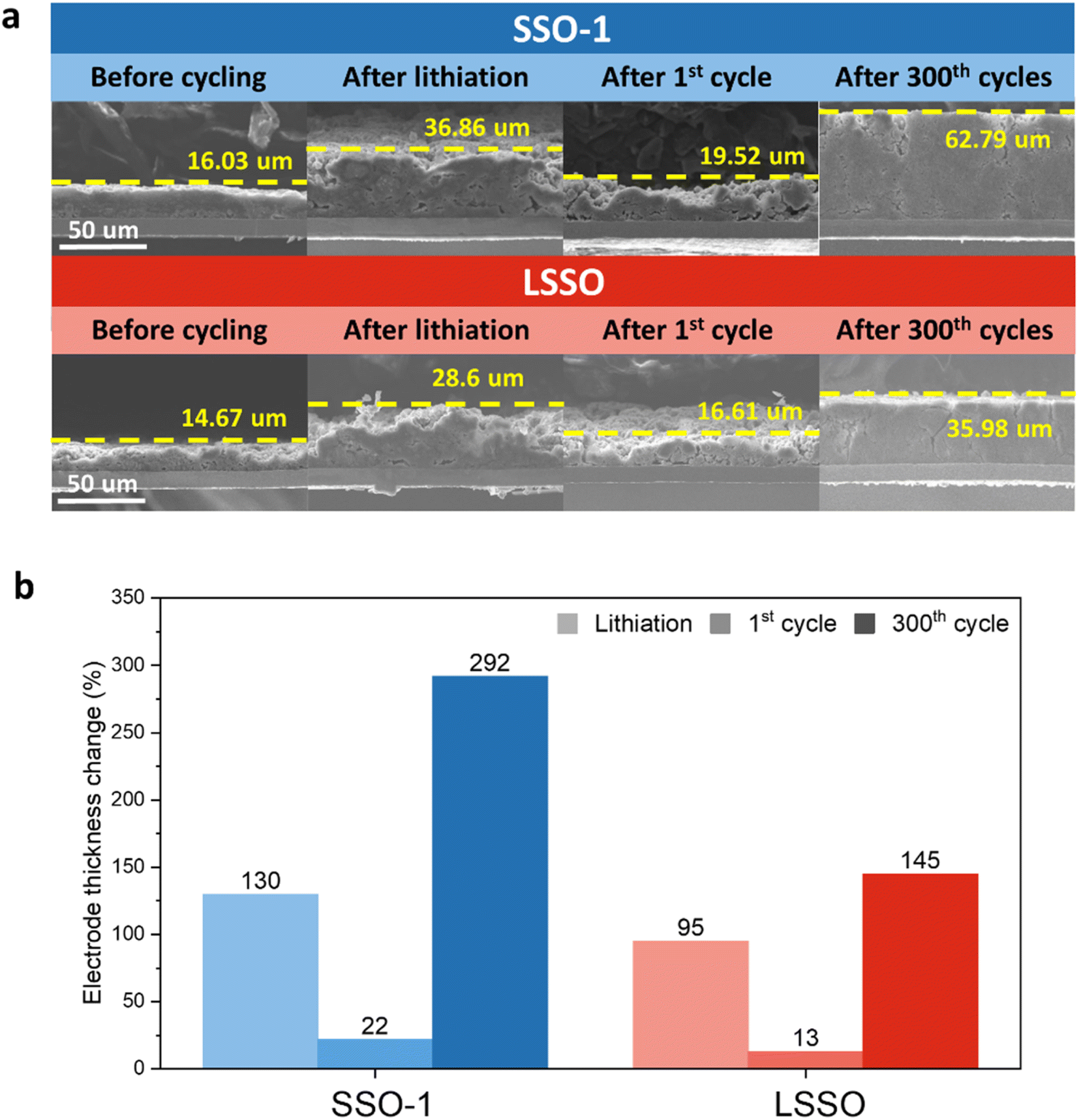 | ||
| Fig. 5 (a) Cross sectional SEM images of the SSO-1, and LSSO electrodes before cycling, after 1 discharge (lithiation), after 1 cycle and after 300 cycles, (b) electrode thickness changes of the SSO-1, and LSSO electrodes after 1 discharge (lithiation), after 1 cycle and after 300 cycles. | ||
To further test the viability of the full cell, a coin type full cell was assembled using SSO-1 and LSSO blended with graphite as the negative electrode (NE) and LiNi0.88Co0.06Mn0.06O2 as the positive electrode. Fig. 6a shows first cycle voltage profiles of full cells employing SSO-1 and LSSO. The first cycle discharge areal capacities of full cells with LSSO as the NE were higher than those of full cells with SSO as the NE (2.81 mA h cm−2 for SSO-1 and 3.29 mA h cm−2 for LSSO), which is mainly due to the improved ICE of the LSSO NE (81.7% for LSSO and 70.7% for SSO-1). The full cell employing LSSO as the NE showed greater discharge areal capacity for 100 cycles after two formation cycles compared to the full cell with SSO-1 as the NE (Fig. 6b). Fig. 6c shows the capacity retention and coulombic efficiency of the full cells. The capacity retention of the LSSO electrode was superior to that of the SSO-1 electrode. Upon prolonged cycling up to 100 cycles, the full cell with LSSO (99.3%) showed higher average coulombic efficiency than the full cell with SSO-1 (98.9%). These results suggest that microstructural modifications, such as incorporating free voids and pre-emptive phases, can enhance both the ICE and cycle performance while also increasing the specific capacity of SiO-based anode materials.
 | ||
| Fig. 6 (a) First cycle voltage profiles in a voltage window of 2.7–4.2 V at a current density of 0.35 mA cm−2 (0.1C), (b) discharge capacities, (c) capacity retention and coulombic efficiencies at a current density of 3.5 mA cm−2 (1C) for the prepared coin-type full cells using SSO-1 and LSSO electrodes. | ||
4 Conclusions
In this study, we demonstrated that lithium and oxygen engineering of SiOx using HEMM and prelithiation simultaneously enhances both reversible capacity and ICE. The resulting porous prelithiated Si-rich SiOx delivered a high reversible capacity of 2093 mA h g−1 with an ICE of 88.1%. Despite the high Si content in these materials, the porous prelithiated Si-rich SiOx electrode showed highly stable capacity retention over 300 cycles. This approach to enhance the reversible capacity of SiOx provides a promising strategy for improving the electrochemical performance of SiO-based anode materials in LIBs.Data availability
The datasets supporting this article have been uploaded as part of the ESI.†Author contributions
Ji Young Kim: conceptualization, investigation, writing – original draft, writing – review & editing and data curation. Dong Jae Chung: conceptualization and investigation. Tae Rim Lee: investigation and methodology. Donghan Youn: investigation and methodology. Hansu Kim: writing – original draft, writing – review & editing, project administration and supervision.Conflicts of interest
There are no conflicts to declare.Acknowledgements
This work was supported by the National Research Foundation of Korea (NRF) grant funded by the Korean government (MSIT) (NRF- 2021M3H4A1A02045967)Notes and references
- J.-Y. Li, Q. Xu, G. Li, Y.-X. Yin, L.-J. Wan and Y.-G. Guo, Mater. Chem. Front., 2017, 1, 1691 RSC.
- Z. Liu, Q. Yu, Y. Zhao, R. He, M. Xu, S. Feng, S. Li, L. Zhou and L. Mai, Chem. Soc. Rev., 2019, 48, 285 RSC.
- S. C. Jung, J. W. Choi and Y. K. Han, Nano Lett., 2012, 12, 5342 CrossRef CAS PubMed.
- M. T. McDowell, S. W. Lee, W. D. Nix and Y. Cui, Adv. Mater., 2013, 25, 4966 CrossRef CAS PubMed.
- H. Li, H. Li, Z. Yang, L. Yang, J. Gong, Y. Liu, G. Wang, Z. Zheng, B. Zhong, Y. Song, Y. Zhong, Z. Wu and X. Guo, Small, 2021, 17, 2102641 CrossRef CAS PubMed.
- Z. Liu, Q. Yu, Y. Zhao, R. He, M. Xu, S. Feng, S. Li, L. Zhou and L. Mai, Chem. Soc. Rev., 2019, 48, 285 RSC.
- J. Woo and S.-H. Baek, RSC Adv., 2017, 7, 4501 RSC.
- J. H. Yom, S. W. Hwang, S. M. Cho and W. Y. Yoon, J. Power Sources, 2016, 311, 159 CrossRef CAS.
- Y.-S. Su, K.-C. Hsiao, P. Sireesha and J.-Y. Huang, Batteries, 2022, 8, 1 Search PubMed.
- A. Bhat, P. Sireesha, Y. S. Chen and Y. S. Su, ChemElectroChem, 2022, 9, 19 CrossRef.
- E. Park, D. J. Chung, M.-S. Park and H. Kim, J. Power Sources, 2019, 440, 1 CrossRef.
- H. J. Kim, S. Choi, S. J. Lee, M. W. Seo, J. G. Lee, E. Deniz, Y. J. Lee, E. K. Kim and J. W. Choi, Nano Lett., 2016, 16, 282 CrossRef CAS PubMed.
- J. Zhao, H. W. Lee, J. Sun, K. Yan, Y. Liu, W. Liu, Z. Lu, D. Lin, G. Zhou and Y. Cui, Proc. Natl. Acad. Sci. U. S. A., 2016, 113, 7408 CrossRef CAS PubMed.
- J. Zhao, J. Sun, A. Pei, G. Zhou, K. Yan, Y. Liu, D. Lin and Y. Cui, Energy Storage Mater., 2018, 10, 275 CrossRef.
- M.-Y. Yan, G. Li, J. Zhang, Y.-F. Tian, Y.-X. Yin, C.-J. Zhang, K.-C. Jiang, Q. Xu, H.-L. Li and Y.-G. Guo, ACS Appl. Mater. Interfaces, 2020, 12, 27202 CrossRef CAS PubMed.
- D. J. Chung, D. Youn, S. Kim, D. Ma, J. Lee, W. J. Jeong, E. Park, J.-S. Kim, C. Moon, J. Y. Lee, H. Sun and H. Kim, Nano Energy, 2021, 89, 1 CrossRef.
- D. J. Chung, D. Youn, J. Y. Kim, W. J. Jeong, S. Kim, D. Ma, T. R. Lee, S. T. Kim and H. Kim, Small, 2022, 18, 2202209 CrossRef CAS PubMed.
- Y. Cao, J. C. Bennett, R. A. Dunlap and M. N. Obrovac, Chem. Mater., 2018, 30, 7418 CrossRef CAS.
- H.-R. Yang, J. Hwang, H. Seo, K. Kim and J.-H. Kim, J. Power Sources, 2022, 519, 1 CrossRef.
- K. Pan, F. Zou, M. Canova, Y. Zhu and J.-H. Kim, J. Power Sources, 2019, 413, 20 CrossRef CAS.
- Q. Pan, P. Zuo, T. Mu, C. Du, X. Cheng, Y. Ma, Y. Gao and G. Yin, J. Power Sources, 2017, 347, 170 CrossRef CAS.
- D. Youn, N. G. Kim, W. J. Jeong, D. J. Chung, J. Y. Kim and H. Kim, ACS Appl. Mater. Interfaces, 2022, 14, 45333 CrossRef CAS PubMed.
- B. Gao, C. Bower, J. D. Lorentzen, L. Fleming, A. Kleinhammes, X. P. Tan, L. E. McNeil, Y. Wu and O. Zhou, Chem. Phys. Lett., 2000, 327, 69 CrossRef CAS.
- A. Hirata, S. Kohara, T. Asada, M. Arao, C. Yogi, H. Imai, Y. Tan, T. Fujita and M. Chen, Nat. Commun., 2016, 7, 11591 CrossRef CAS PubMed.
- W. J. Jeong, D. J. Chung, D. Youn, N. G. Kim and H. Kim, Energy Storage Mater., 2022, 50, 740 CrossRef.
- C. Shen, M. Ge, L. Luo, X. Fang, Y. Liu, A. Zhang, J. Rong, C. Wang and C. Zhou, Sci. Rep., 2016, 6, 31334 CrossRef CAS PubMed.
- W. Wang, Z. Favors, R. Ionescu, R. Ye, H. H. Bay, M. Ozkan and C. S. Ozkan, Sci. Rep., 2015, 5, 8781 CrossRef CAS PubMed.
- Z. Cheng, H. Jiang, X. Zhang, F. Cheng, M. Wu and H. Zhang, Adv. Funct. Mater., 2023, 33, 26 Search PubMed.
- Y. S. Yoon, S. H. Jee, S. H. Lee and S. C. Nam, Surf. Coat. Technol., 2011, 206, 553 CrossRef CAS.
- M. Sohn, H.-I. Park and H. Kim, Chem. Commun., 2017, 53, 11897 RSC.
- J. Jakubowicza, K. Smardza and L. Smardz, Phys. E Low-dimens. Syst. Nanostruct., 2007, 38, 139–143 CrossRef.
- T. Kasukabe, H. Nishihara, S. Iwamura and T. Kyotani, J. Power Sources, 2016, 319, 99 CrossRef CAS.
- P. K. Alaboina, J.-S. Cho, M.-J. Uddin and S.-J. Cho, Electrochim. Acta, 2017, 258, 623 CrossRef CAS.
Footnote |
| † Electronic supplementary information (ESI) available. See DOI: https://doi.org/10.1039/d4ta08234f |
| This journal is © The Royal Society of Chemistry 2025 |