
 Open Access Article
 This Open Access Article is licensed under a Creative Commons Attribution-Non Commercial 3.0 Unported Licence
The pendant drop experiment for aggregates of cohesive granular particles†
Yasaman
Heshmatzadeh
 a,
Jean-Christophe
Ono-dit-Biot
a and
Kari
Dalnoki-Veress
*ab
a,
Jean-Christophe
Ono-dit-Biot
a and
Kari
Dalnoki-Veress
*ab
aDepartment of Physics & Astronomy, McMaster University, Hamilton, ON L8S 4L8, Canada. E-mail: dalnoki@mcmaster.ca
bUMR CNRS Gulliver 7083, ESPCI Paris, PSL Research University, 10 rue Vauquelin, 75005 Paris, France
First published on 4th March 2025
Abstract
The pendant drop experiment can be used to study the interfacial tension of a liquid. Here we perform a similar experiment for a granular system. When a dense aggregate of cohesive particles extrudes from an orifice, a cluster of particles detaches, similar to the detachment of a liquid drop. We investigate the volume of the clusters formed from close-packed cohesive oil droplets in an aqueous solution. Our findings reveal that the volume of the clusters depends on the size of the orifice as well as the cohesion strength. Interestingly, we observe that the droplet size does not significantly impact the average cluster volume. We establish a simple scaling law that governs the size of a granular cluster which differs from that of a classic pendant drop. We propose that the key difference between continuum and granular systems is the constraints on rearrangements within the cohesive particles that prevent the clusters from adopting a minimal surface structure, as is the case for a classic pendant drop.
Introduction
The contrast between pouring ketchup slowly from a bottle and water dripping from a faucet raises the question: what determines the size of drops in these distinct cases? While the answer to this question is solved for simple molecular liquids by Tate in 1864,1 the answer is not so obvious for the case of complex fluids, cohesive granular materials, suspensions and emulsions. Extrusion of dense aggregates of cohesive particles and foams is commonplace. Of particular interest is the size of clusters of dense drop-like aggregates as they extrude from an orifice due to gravity or other driving forces. These granular aggregate ‘drops’ are relevant to many industrial applications, such as spraying, ink-jet printing and the food industry.2–4 In addition, clusters of granular particles and suspensions play a vital role in advanced technologies such as drug delivery5 and bioprinting,6,7 where precise control over cluster size is paramount.The classic pendant drop experiment is a simple method for studying the surface or interfacial tension of liquids.8 Typically a needle, connected to a reservoir, is filled with a liquid. The liquid is slowly pushed through the needle such that the system remains in a quasi-static state, and a drop of liquid forms at the tip of the needle. The capillary force stabilizes the drop against gravity. As the pendant drop grows, gravity eventually overcomes capillarity and the drop detaches from the needle. The volume of the detached drop, V, is obtained from a simple force balance between the gravitational and capillary forces, as determined experimentally by Tate in 1864, and commonly referred to as Tate's Law.1
Multiple studies have shown that the presence of cohesive forces in granular materials can lead to properties which are reminiscent of liquids with surface tension (see the review by Sharma and Sauret9). For example, the breaking up of a jet of granular particles into drop-like clusters downstream,10–13 is strikingly similar to the Plateau–Rayleigh instability seen when a thin jet of water breaks up into drops. Cohesive forces are the primary origin of cluster formation, regardless of the source of cohesion: be it capillary bridges, van der Waals forces, or even both,10,12,13 surface charges, and even geometrical constraints between particles.14 Collectively, one can conclude that the interparticle cohesion in granular materials can result in effects that are analogous to the capillary forces in molecular liquids; although the underlying physics is different and the aggregates do not necessarily minimize their surface area.
The pendant drop experiment can be used to study drop formation of complex fluids like suspensions, dispersions, and cohesive granular materials. In the granular version of the pendant drop experiment, an aggregate of cohesive particles or a suspension with desired particle density is slowly pushed through an orifice. Gravity pulls on the aggregate and the cohesion among the particles stabilizes the formation of a dense drop-like cluster, similar to the role of surface tension in liquids. The cluster grows until a certain size is reached, after which the cluster detaches from the orifice. However, when the thermal energy of the particles is small and Brownian motion is insignificant, the system is athermal, and the particles do not readily rearrange. If the system is athermal, the stress acting on a cluster must be large enough to cause a wholesale rearrangement for the detachment of a cluster. Considering the yield stress characteristics of such amorphous materials, it is instructive to investigate how drop-like clusters form in these systems.15
While drop formation and pinch-off of simple liquids has been studied extensively,16 formation of drop-like clusters consisting of granular particles, which we refer to as ‘granular drops’, is not fully understood. Unlike a drop of liquid with the number of molecules approaching Avogadro's number, granular drops may be composed of tens-to-thousands of particles. Given the relatively low particle number, heterogeneities, like local variations in packing fraction, as well as specific local rearrangements are important. The formation of granular drops has been studied over the years, using different granular systems, and with suspensions of varying particle densities. Current studies on granular pendant drops mostly focus on the effect of granularity on the dynamics of pinch-off.17–21 Our focus is on the volume of the granular drops which is relevant to advanced applications, such as drug delivery5 and bioprinting.6,7
Here we use densely packed oil droplets with controlled cohesion in an aqueous solution. The effect of gravity on the buoyant oil droplets causes the aggregate to extrude slowly from an orifice, while the cohesive interaction, resulting from the depletion interaction,22 stabilizes the growing granular drop. We characterize the volume of the detached clusters, while varying the cohesion strength, the orifice size, and the droplet size. We find that the average volume of the clusters is proportional to the orifice area, which is in contrast with the case of the classic liquid pendant drop experiment, where the volume depends linearly on the orifice perimeter. Moreover, the volume depends on a parameter that emerges from a balance between the cohesion strength and the effective buoyancy, termed the granular capillary length, δ.23 Note that for brevity we refer to the effective buoyancy, with which we imply the contribution of both the force of gravity (dependent on the density of the droplet), and the buoyancy (dependent on the density of the aqueous solution). We conclude that the overall properties of our cohesive granular system is reminiscent of viscoplastic materials under tensile stress,24 and that the average volume of the granular drop follows a simple scaling law, despite the nuances due to granularity. We note that the granular drop is composed of small oil droplets which are the granular particles: To avoid confusion we refer to the mesoscale aggregate as the cluster or drop, while the granular particles will be referred to as droplets i.e. it is the cluster of oil droplets that make up the granular drop.
Methods
The experimental setup
A schematic diagram of the experimental setup is shown in Fig. 1(a). The experiment is carried out in a cuvette (BRAND, Germany), which is filled with an aqueous solution of a surfactant, sodium dodecyl sulfate (SDS)(BioShop), and NaCl (Caledon). A layer of mineral oil is added on top of the solution, to prevent evaporation and ensure a constant concentration. | ||
| Fig. 1 (a) Schematic of the experimental setup. A cuvette is filled with an aqueous solution. (i) is the funnel, where droplets accumulate, (ii) is the funnel holder. (iii) is the lid that seals the funnel. (iv) is the micropipette that produces the droplets and (v) is an oil layer that prevents any evaporation. (b) An optical microscopy image, showing the tip of the funnel at the bottom and a cluster of oil droplets. The cluster rises because of buoyancy. The specific parameters in (b) are: Cm = 104 mM, R = 44 μm and rd = 12.6 μm. The scale bar on the right is 250 μm. The edge of the cluster is shown in blue. The cluster height hmax and width of the cluster at height z, wz are shown. | ||
The surfactant serves two purposes. First of all, SDS stabilizes the oil droplets against coalescence. Second, since SDS forms micelles above the critical micelle concentration (CMC), the SDS induces a tuneable short-range cohesion due to the depletion interaction.22 A higher concentration of micelles in solution leads to a stronger cohesive interaction between droplets.23 The volume fraction of micelles is given by ϕm = (C−CCMC)NA/Na, where NA is Avogadro's number, CCMC is the critical micelle concentration,25 and the number of SDS molecules in one micelle, Na ≈ 120.26 We use Cm = C−CCMC as the control parameter in the experiments presented, since this quantity is directly proportional to the micelle volume fraction ϕm. Brochard-Wyart and de Gennes showed that the cohesive force between two vesicles is linearly proportional to the product of the micelle concentration and the droplet radius.27 This relationship was directly validated by Ono-dit-Biot et al.23 for the system presented here. Ono-dit-Biot et al. found that that the cohesive force, Fadh, is linearly proportional to the micelle concentration, as well as the droplet size, rd: Fadh ∝ rdCm. The SDS concentration ranges from ∼23 mM to 173 mM. Based on previous experiments,23 this range of SDS concentration gives rise to cohesion strengths, 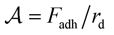 , of 2.87 μN m−1 to 21.62 μN m−1. As SDS is an ionic surfactant, NaCl is added to the solution to screen electrostatic interactions among SDS molecules. The NaCl concentration is held constant at ∼260 mM (1.50% (w/w)) for all the experiments. It has been shown that the presence of NaCl in an aqueous solution of SDS decreases the CMC from 8 mM for SDS in pure water, to ∼1 mM for the NaCl concentration that we work with.28,29 Therefore, CCMC = 1 mM is used to obtain Cm.
The droplets, with radii ∼10 μm, are made using a micropipette. To prepare the micropipettes, we pull glass capillary tubes with an outer diameter of 1.00 mm, and an inner diameter of 0.58 mm (World Precision Instruments, USA), using a pipette puller (Narishige, Japan), so that a long tapered end forms (see schematic in Fig. 1(a)), with a tip opening in the range of tens of micrometers. We then bend the micropipette with heat to 90° at two points. With the micropipette located appropriately within the experimental chamber, the droplets are produced and fill a capped funnel as shown in Fig. 1(a). Light paraffin oil (Sigma-Aldrich) is pushed through the micropipette via tubing (inner diameter 1/32′′; Tygon S3, formula E-3603), that is connected to a reservoir open to atmospheric pressure. The height of the reservoir controls the pressure at the pipette tip and determines the rate of droplet production via the snap-off instability.30,31 When the pipette is immersed in the solution, droplets are produced at a frequency of about 1 Hz. Once the droplet production starts, it can continue for days. This method is a reliable way of making highly monodisperse droplets.30 We note that the degree of polydispersity is bounded by the uncertainty of droplet size measurement,30 which is approximately 0.4 μm in this study. Barkley et al.30 have shown that the size of the droplets produced by the snap-off method is proportional to the size of the micropipette tip. We control the droplet size by controlling the size of the micropipette tip and produce droplets with radius, rd, that ranges from ∼5.0 μm to 13.5 μm.
The funnel is manually made by heating a glass pipette (outer diameter: 1.8 mm, inner diameter: 1.5 mm)(Kimble, USA) over an alcohol burner, then manually pulling it. We cut the pulled glass at a certain length with desired width, then heat it again, so that the glass gently melts to form a small and smooth circular orifice, without the orifice closing. The tip is then polished so that the orifice is flat and perpendicular to the pipette using sandpaper (grit 600 up to 1000). This process can be used to fine-tune the orifice size. Here we use three different funnels with orifice radii, R, of 44 μm, 70 μm and 93 μm. The funnel is covered by a removable lid that is 3D printed using PLA, so an aggregate of droplets can form. When the aggregate is big enough to produce ∼200 clusters, we remove the lid and start the experiment. A microscope, consisting of a camera (ThorLabs, USB2.0 Digital Camera) equipped with an objective (4×, Nikon) records images, as shown in Fig. 1(b). Videos of typical experiments can be found in the ESI.†
Cluster characterization
Image analysis is performed using custom code and direct length measurements were done on Fiji ImageJ.32 The occupied volume of the clusters is found as follows. Fig. 1(b) shows a raw image of a sample cluster. The edge of each cluster is detected, using a code, based on the Sobel filter.33,34 Knowing the coordinates of the edge, we determine the width of the cluster, wz, at any vertical coordinate z. Using the edge detection results, we also find the maximum height of the cluster, hmax.Since we image along one projection and the funnel is axisymmetric, we assume that the clusters do not have a directional bias and are thus axisymmetric as well. As a result, the cross section of the cluster is estimated as a circle with diameter wz, and the volume element will be a disc with the diameter wz and the thickness dz, which is one pixel: dV = (πwz2/4)dz The volume of the granular cluster that is occupied by droplets, V, depends on the packing fraction, ϕ. To find the volume of the cluster occupied by droplets we simply do a discreet integration of the volume of each disc, over the height of the cluster:
 | (1) |
For simplicity, we assume that ϕ is constant for all experiments. The value of ϕ for the packed aggregate is a number between random close packing and hexagonal close packing, ranging from 0.64 to 0.74. For all the results shown in this article, we have chosen the packing fraction to be ϕ = 0.7.
Cluster selection
To promote cluster formation rather than extrusion of droplets in a jet, we maintain a low flow rate for aggregates exiting the orifice with Reynolds number, Re ∼ 0.01 (this is obtained using the speed at which the cluster forms, not the motion of the cluster in the solution as it rises). This low flow rate is controlled by two factors: first, the dome-shaped geometry of the funnel, which restricts the flow,35 and second, limiting the number of droplets in the funnel to reduce the hydrostatic pressure exerted by the aggregate in the funnel.We choose a time-window of each experiment for analysis based on two criteria: first, we select clusters from the later stages of the experiment because the lower hydrostatic flow results in slow cluster production; second, we plot the cluster volume time series for each experiment and ensure that the volume of clusters does not meaningfully change. This approach provides enough clusters for a reliable statistical analysis while minimizing the effect of hydrostatic pressure on cluster size and ensuring that we are in a quasi-static regime for cluster pinch-off.
An example is shown in Fig. 2(a), where we plot the volume of the clusters in chronological order for a typical experiment. To show the long-term trends in the cluster volume, we smooth the data by plotting the simple moving average for 20 consecutive clusters. The total average cluster volume is shown as a reference. The moving average shows that the volume fluctuates around a mean value and is not impacted by the small hydrostatic pressure acting on the aggregate in the funnel. The volume distribution is shown in Fig. 2(b), and the volume fluctuation is in part due to the granular nature of the system, which affects the dynamics of cluster pinch off.21 For each experiment, we take the average cluster volume as the characteristic volume and the standard deviation as the ‘error’.
 | ||
| Fig. 2 (a) Volume of the clusters plotted for an experiment in chronological order. The red line shows the average volume and the black line shows the moving average over a window of 20 clusters. Despite the high number of clusters (N = 187), no meaningful change is observed in cluster volume. In this particular experiment, the parameters are: Cm = 156 mM, R = 70 μm, and rd = 10.2 μm. (b) Volume distribution, from which an average volume can be extracted. | ||
Another consideration in cluster selection is the formation of small satellite clusters, which can be seen in Fig. 3. These are the smaller clusters that occasionally form when the main cluster is pinching off. Due to rearrangement of the droplets in the thin neck, packing fraction varies locally, leading to break up at multiple points and leaving a smaller cluster trailing the main cluster. Since the size of these small clusters is not set by balance between cohesion and the effective buoyancy, which is the focus of this work, we exclude the small fragments of satellite clusters.
 | ||
| Fig. 3 The formation of a cluster. The droplets rearrange to form a long neck, similar to homogeneous liquids.36,37 The cluster forms a neck, which can break up at multiple points to form a satellite cluster. The time interval between any two consecutive image is 0.25 seconds. The parameters for this particular experiment are: Cm = 173 mM, R = 93 μm and rd = 4.9 μm. | ||
Results and discussion
In the pendant drop experiment for a molecular liquid (continuum liquid), the volume of a detached liquid drop is given by Tate's Law, and obtained from a simple force balance between the gravitational and capillary forces.1,38 The detached drop volume is proportional to Rγ/(ρg), where γ is the surface tension, ρ is the density of the liquid, R is the orifice radius, and g is the gravitational acceleration. The capillary length38 is a length scale that characterizes the importance of gravity compared to surface tension, and is given by . We can then rewrite the volume of the detached molecular-liquid drop as ∝ Rlc2.
Although continuum and granular pendant drops share similarities, they differ significantly in particle rearrangement. In the classic pendant drop, the liquid molecules rearrange rapidly compared to the time scale of drop formation. This rapid reorganization, driven by thermal motion, enables the liquid to minimize surface area through capillary forces. As a result, a spherical drop with minimum surface-to-volume ratio forms upon detachment resulting in the linear scaling with R for Tate's Law (i.e., γR holds the drop to the orifice).
In contrast, the particles in the granular pendant drop studied here do not rearrange readily because they are athermal. Furthermore, the cohesive, monodisperse droplets in the granular case form relatively stable poly-crystalline structures upon aggregation. For wholesale rearrangement to occur, bonds between neighbouring droplets must break, requiring an external stress on the aggregate. When stresses remain below a threshold determined by the macroscopic cohesion strength,39 the aggregate retains its shape. Ono-dit-Biot and colleagues studied the rearrangement of a single layer of monodisperse oil droplets under compression, observing that the aggregate withstands compressive stress up to a yield point,40 after which a wholesale rearrangement occurs. This resistance to rearrangement influences the shape of the resulting cluster. In the present study, dense aggregates extrude from a circular orifice. Therefore, the aggregate adopts a near-cylindrical shape as it exits. Due to lack of sufficient compressive stress in the vertical direction, the cluster retains its shape. As the cluster detaches, a long neck starts to form, due to the tension in the vertical direction and gives rise to the spindle-like shape of the cluster shown in Fig. 3.
A total of 36 experiments are carried out with eight different values of the micelle concentration, three funnel opening sizes, and droplet sizes ranging from ∼5.0 μm to 13.5 μm. For each experiment we obtain the average volume of the clusters, 〈V(Cm,rd,R)〉, as described above and shown in Fig. 2. Just as gravity opposes the capillary force for the classic pendant drop experiment, we assume that the forces that affect the cluster volume are the cluster cohesion and the effective buoyancy. We further assume that the quasi-static experiments minimize the contribution of viscous dissipation. Furthermore, the droplets can be treated as frictionless since we can assume no friction at liquid interfaces.23,40–42
We first qualitatively investigate the role of cohesion strength and funnel orifice size on the cluster volume. Fig. 4 (left box) shows typical clusters from two experiments in which the droplet size and orifice size are kept constant, while the SDS micelle concentration is varied. We observe that higher cohesion leads to larger clusters. This observation makes sense in the light of our assumptions: with R and rd held constant, the number of droplets in contact at the orifice area is the same between the two experiments. However, with a higher cohesion the effective buoyant force needed for a cluster to detach must be larger, resulting in the formation of a larger cluster.
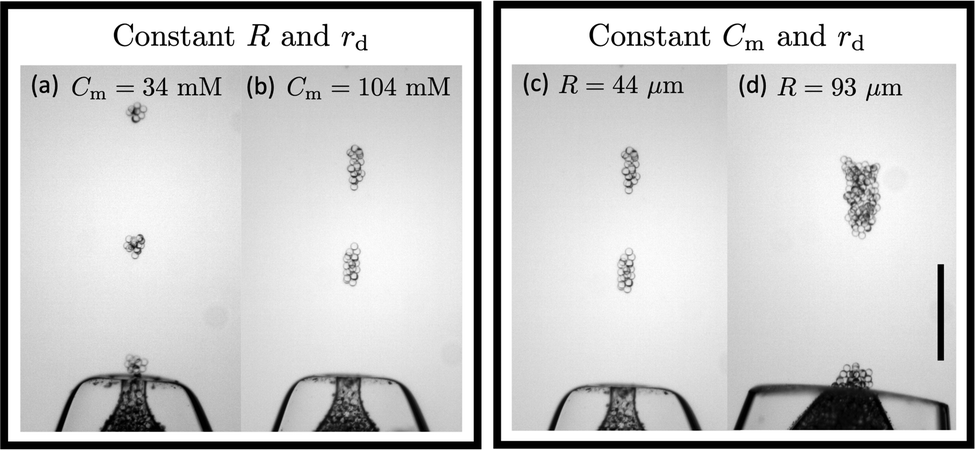 | ||
| Fig. 4 Left box: The effect of micelle concentration on the cluster size. Both the orifice size and droplet size are kept constant at R = 44 μm and rd = 13 μm. Cohesion strength among the droplets is lower in (a) than in (b). As a result, clusters in (a) are smaller than in (b). Right box: The effect of orifice size on the cluster size. Both the micelle concentration and droplet size are kept constant at Cm = 104 mM and rd = 13 μm. Orifice size is smaller in (c) than in (d). As a result, clusters in (c) are smaller than in (d). | ||
Next we turn to the qualitative dependence of the cluster size on the orifice size, while keeping the cohesion strength and droplet size constant. As can be seen in Fig. 4 (right box), we observe that a larger orifice results in a larger cluster when compared to the smaller orifice. This correlation is consistent with the assumptions: even though the cohesive force remains unchanged, as we increase the orifice size, the cross-sectional area, and hence the number of droplets in contact at the orifice area increases. Therefore, a higher effective buoyant force is required to form a cluster emerging from a larger orifice.
The results for all the experiments are shown in Fig. 5(a), where the average occupied volume of the clusters, 〈V〉 is plotted as a function of Cm, which is proportional to the micelle concentration. The data show that increasing cohesion results in larger cluster volumes.
 | ||
| Fig. 5 (a) Average cluster volume plotted versus Cm which is proportional to the cohesion strength. The error bars in all the plots represent the standard deviation of the data. (b) Average cluster volume is plotted versus δ to show an intermediate collapse in accordance with eqn (3), where the data from any orifice falls on the same line. Darkest line corresponds to the smallest orifice and lightest corresponds to the largest orifice. (c) Average cluster volume as a function of R2δ as suggested by eqn (3) with ξ = 2.58 ± 0.15. (d) Normalized cluster volume versus droplet radius. The line of best fit shows a negligible correlation with a slope of −0.06 ± 0.04. | ||
We can develop a simple model for the dependence of the average cluster volume as a function of the experimental parameters. In the experiments, an aggregate of oil droplets experiences an upwards body force due to the effective buoyancy which depends on the density difference Δρ between the oil droplets and the aqueous solution. Just as capillary forces stabilize the drop in the classic pendant drop experiment, here the forming cluster is stabilized by the cohesive force Fadh between the droplets, which prevents the droplets from emerging one-by-one. The cohesion strength in the granular pendant drop is defined as  ; and dimensionally, this is a force per unit length.23 This cohesion strength is analogous to the surface tension of the liquid γ in the classic pendant drop. Thus, by analogy with the definition of the capillary length for simple liquids,
  , we can define the granular capillary length, δ, as:23
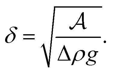 | (2) |
The granular capillary length sets a natural length scale for our system of droplets,23,41 since it results from a balance between the effect of cohesion among the droplets and the effective buoyancy.
In order to formulate a quantitative description for the occupied volume of the granular pendant drop, we use a simple scaling argument. There are three natural length scales in our system: the droplet radius, rd, the orifice radius, R, and the granular capillary length, δ. Given the relatively large number of droplets in each cluster, as stated earlier, we assume that the packing fraction is independent of the size of the droplets. Hence, the cluster size is also independent of the size of the droplets, i.e. rd does not affect the volume of oil in the clusters which causes the effective buoyancy. As will be shown below, this assumption is validated by experiments. In 3D we can then write that V ∝ R3−αδα. The vertical scale of the cluster depends on the balance between the effective buoyancy and adhesion, given by δ, suggesting a linear dependence of the volume on δ with α = 1. We conclude then that the occupied cluster volume can be written as:
| V = ξR2δ, | (3) |
We can test the proportionality relation of eqn (3) by plotting the average occupied volume 〈V〉 first versus δ for an intermediate collapse and then versus R2δ. The results are shown in Fig. 5(b) and (c). We see an excellent collapse of the data for the 36 experiments. The best fit lines are given by eqn (3) with ξ = 2.58 ± 0.15. We note that as expected from the model, ξ indeed emerges as a constant of order 1. Lastly, above we made the assumption that rd does not play a role in determining the average cluster volume and only emerges though the value of δ. We can test this assumption by plotting the normalized volume 〈V〉/R2δ versus rd. The results in Fig. 5(d) show that the data is consistent with no dependence of the cluster volume on the droplet size; if there is a dependence, the dependence is clearly weak.
Conclusion
In conclusion, we have developed an experimental setup to replicate the pendant drop experiment for dense aggregates of cohesive droplets. We have studied the resultant cluster size as a function of cohesion strengths, orifice, and droplet sizes. We find that the volume of the cluster is proportional to the orifice area multiplied by the granular capillary length, a characteristic length of the system that emerges from a balance of cohesion and buoyancy, . The emergence of the granular capillary length as a critical parameter has appeared in other works as well.23,41 The scaling law in this cohesive and frictionless granular system, V ∝ R2δ, is different from that of the classic pendant drop, where Tate's Law shows that V ∝ Rlc2. The crossover from the linear dependence on R for a molecular liquid, to the dependence on R2 for the granular system, is due to the wholesale rearrangements of particles required in the athermal system, which leads to the paste-like response of the droplet aggregates. Thus we find a difference in the shape of the granular pendant drop and the scaling law, when compared to molecular liquids. We expect that as one decreases the size of particles that make up the granular aggregate and reduces the cohesion, thermal effects become important enabling rearrangements within the system. One would expect a crossover from a square dependence on the orifice size to a linear dependence when the system becomes thermalized, akin to the molecular system.
Data availability
The data underlying this work are available via the zenodo repository at https://zenodo.org/records/14994206.Conflicts of interest
There are no conflicts to declare.Acknowledgements
We thank Johnathan Hoggarth for many fruitful discussions during the project, Hamza Khattak for providing useful feedback on the manuscript and Felipe Rivera-Madrinan for initial work on the system studied. We acknowledge the Natural Sciences and Engineering Research Council of Canada for funding of this project.References
- T. Tate, London Edinburgh Dublin Philos. Mag. J. Sci., 1864, 27, 176–180 CrossRef.
- G. Øye, S. Simon, T. Rustad and K. Paso, Curr. Opin. Food Sci., 2023, 50, 101003 CrossRef.
- M. Silva and J. Chandrapala, Food Rev. Int., 2023, 39, 1462–1484 CrossRef CAS.
- T. Luo and Z. Wei, Food Front., 2023, 4, 1622–1642 CrossRef CAS.
- G. Villar, A. D. Graham and H. Bayley, Science, 2013, 340, 48–52 CrossRef CAS PubMed.
- S. Liu, L. Cheng, Y. Liu, H. Zhang, Y. Song, J.-H. Park, K. Dashnyam, J.-H. Lee, F. A.-H. Khalak, O. Riester, Z. Shi, S. Ostrovidov, H. Kaji, H.-P. Deigner, J. L. Pedraz, J. C. Knowles, Q. Hu, H.-W. Kim and M. Ramalingam, J. Tissue Eng., 2023, 14 DOI:10.1177/20417314231187113.
- X. Li, B. Liu, B. Pei, J. Chen, D. Zhou, J. Peng, X. Zhang, W. Jia and T. Xu, Chem. Rev., 2020, 120, 10793–10833 CrossRef CAS PubMed.
- C. E. Stauffer, J. Phys. Chem., 1965, 69, 1933–1938 CrossRef CAS.
- R. Sharma and A. Sauret, Soft Matter, 2025 10.1039/D4SM01324G.
- S. R. Waitukaitis, H. F. Gruetjen, J. R. Royer and H. M. Jaeger, Phys. Rev. E, 2011, 83, 051302 CrossRef PubMed.
- G. Prado, Y. Amarouchene and H. Kellay, Phys. Rev. Lett., 2011, 106, 198001 CrossRef CAS PubMed.
- J. R. Royer, D. J. Evans, L. Oyarte, Q. Guo, E. Kapit, M. E. Möbius, S. R. Waitukaitis and H. M. Jaeger, Nature, 2009, 459, 1110–1113 CrossRef CAS PubMed.
- M. E. Möbius, Phys. Rev. E, 2006, 74, 051304 CrossRef PubMed.
- T. Knippenberg, A. Lüders, C. Lozano, P. Nielaba and C. Bechinger, Sci. Rep., 2022, 12, 11525 CrossRef CAS PubMed.
- D. Bonn, M. M. Denn, L. Berthier, T. Divoux and S. Manneville, Rev. Mod. Phys., 2017, 89, 035005 CrossRef.
- J. Eggers, Z. Angew. Math. Mech., 2005, 85, 400–410 CrossRef.
- R. J. Furbank and J. F. Morris, Int. J. Multiphase Flow, 2007, 33, 448–468 CrossRef CAS.
- C. Bonnoit, T. Bertrand, E. Clément and A. Lindner, Phys. Fluids, 2012, 24, 043304 CrossRef.
- T. Bertrand, C. Bonnoit, E. Clément and A. Lindner, Granular Matter, 2012, 14, 169–174 CrossRef CAS.
- M. Z. Miskin and H. M. Jaeger, Proc. Natl. Acad. Sci. U. S. A., 2012, 109, 4389–4394 CrossRef CAS PubMed.
- V. Thiévenaz and A. Sauret, Proc. Natl. Acad. Sci. U. S. A., 2022, 119, e2120893119 CrossRef PubMed.
- R. Jones, Soft Condensed Matter, OUP, Oxford, 2002 Search PubMed.
- J.-C. Ono-dit Biot, T. Lorand and K. Dalnoki-Veress, Phys. Rev. Lett., 2020, 125, 228001 CrossRef CAS PubMed.
- P. Coussot and F. Gaulard, Phys. Rev. E, 2005, 72, 031409 CrossRef CAS PubMed.
- J. Bibette, D. Roux and B. Pouligny, J. Phys. II, 1992, 2, 401–424 CrossRef CAS.
- B. L. Bales, L. Messina, A. Vidal, M. Peric and O. R. Nascimento, J. Phys. Chem. B, 1998, 102, 10347–10358 CrossRef CAS.
- F. Brochard-Wyart and P.-G. de Gennes, C. R. Phys., 2003, 4, 281–287 CrossRef CAS.
- C. Thévenot, B. Grassl, G. Bastiat and W. Binana, Colloids Surf., A, 2005, 252, 105–111 CrossRef.
- B. Naskar, A. Dey and S. P. Moulik, J. Surfact Detergents, 2013, 16, 785–794 CrossRef CAS.
- S. Barkley, E. R. Weeks and K. Dalnoki-Veress, Eur. Phys. J. E, 2015, 38, 138 CrossRef PubMed.
- S. Barkley, S. J. Scarfe, E. R. Weeks and K. Dalnoki-Veress, Soft Matter, 2016, 12, 7398–7404 RSC.
- J. Schindelin, I. Arganda-Carreras, E. Frise, V. Kaynig, M. Longair, T. Pietzsch, S. Preibisch, C. Rueden, S. Saalfeld, B. Schmid, J.-Y. Tinevez, D. J. White, V. Hartenstein, K. Eliceiri, P. Tomancak and A. Cardona, Nat. Methods, 2012, 9, 676–682 CrossRef CAS PubMed.
- I. Sobel, Presentation at Stanford A.I. Project 1968, 2014 Search PubMed.
- S. Van Der Walt, J. L. Schönberger, J. Nunez-Iglesias, F. Boulogne, J. D. Warner, N. Yager, E. Gouillart and T. Yu, PeerJ, 2014, 2, e453 CrossRef PubMed.
- D. López-Rodríguez, D. Gella, K. To, D. Maza, A. Garcimartín and I. Zuriguel, Phys. Rev. E, 2019, 99, 032901 CrossRef PubMed.
- X. D. Shi, M. P. Brenner and S. R. Nagel, Science, 1994, 265, 219–222 CrossRef CAS PubMed.
- X. Zhang and O. A. Basaran, Phys. Fluids, 1995, 7, 1184–1203 CrossRef CAS.
- P.-G. Gennes, F. Brochard-Wyart and D. Quéréet al., Capillarity and wetting phenomena: drops, bubbles, pearls, waves, Springer, 2004 Search PubMed.
- B. Andreotti, Y. Forterre and O. Pouliquen, Granular Media: Between Fluid and Solid, Cambridge University Press, 1st edn, 2013 Search PubMed.
- J.-C. Ono-Dit-Biot, P. Soulard, S. Barkley, E. R. Weeks, T. Salez, E. Raphael and K. Dalnoki-Veress, Soft Matter, 2021, 17, 1194–1201 RSC.
- J. Hoggarth, J.-C. Ono-dit biot and K. Dalnoki-Veress, Soft Matter, 2023, 19, 3747–3753 RSC.
- J.-C. Ono-dit-Biot, P. Soulard, S. Barkley, E. R. Weeks, T. Salez, E. Raphael and K. Dalnoki-Veress, Phys. Rev. Res., 2020, 2, 023070 CrossRef CAS.
Footnote |
| † Electronic supplementary information (ESI) available. See DOI: https://doi.org/10.1039/d4sm01424c |
| This journal is © The Royal Society of Chemistry 2025 |