
 Open Access Article
 This Open Access Article is licensed under a Creative Commons Attribution-Non Commercial 3.0 Unported Licence
Graphene nanoplatelet–nickel ferrite coated textile-based embroidered capacitive pressure sensor for wearable electronics application†
Aqrab
ul Ahmad
*ab,
Saima
Qureshi
 *c,
Mitar
Simić
c,
Hafiz
Abdul Mannan
d,
Sonam
Goyal
e,
Francis Leonard
Deepak
b and
Goran M.
Stojanović
c
*c,
Mitar
Simić
c,
Hafiz
Abdul Mannan
d,
Sonam
Goyal
e,
Francis Leonard
Deepak
b and
Goran M.
Stojanović
c
aDepartment of Physics, Riphah International University Faisalabad Campus, 38000, Pakistan. E-mail: Aqrab.Ahmad@inl.int
bNanostructured Materials Group, International Iberian Nanotechnology Laboratory, 4715-330 Braga, Portugal
cFaculty of Technical Sciences, University of Novi Sad, Trg Dositeja Obradovića 6, Fruškogorska 11, 21000 Novi Sad, Serbia. E-mail: saima.qureshi@uns.ac.rs
dInstitute of Polymer and Textile Engineering, University of the Punjab, Quaid-E-Azam Campus, Lahore, 54590, Pakistan
eArya College of Engineering & Research Center, 302003, Jaipur, India
First published on 15th July 2025
Abstract
In recent times, pressure sensors developed from e-textiles have gained tremendous attention due to their flexibility, comfort, real-time detection, and potential for long-term applications when integrated with monitoring devices. The current research focuses on designing a capacitive pressure sensor comprising a porous textile substrate for electrodes and a porous textile-based dielectric layer. A solution processing approach was used to formulate a graphene nanoplatelet/nickel ferrite (GNP–NiFe2O4) composite, and the dip-coating technique was utilized to coat the sensing layer on pure cotton and cotton–polyester fabric. The coated fabric was integrated as a dielectric layer above the interdigitated capacitor to observe the capacitance variation under applied pressure. Additionally, the effects of the volume percentage of GNPs in GNP–NiFe2O4 and the fabric type on the sensor performance were also considered. The highest sensitivity was obtained for the cotton/polyester textile coated with 10 wt% GNP–NiFe2O4. The proposed pressure sensor can reach the linear band in the range from 11 kPa to 100 kPa, making it suitable for pressure sensing in cases of physical impact. Furthermore, a large-area, wireless array of six pressure sensors has been fabricated from the optimized dielectric textile coated with GNP–NiFe2O4. The change in the pressure range due to multiple sensors can be monitored on a smartphone, enabling real-time applications in monitoring human body motion, human tactile sensing, or any external pressure in cases of gait or grip.
1. Introduction
Capacitive-based sensing devices are frequently used by researchers because of their numerous applications in wearable electronic devices, exceptional performance, inexpensive fabrication techniques, and straightforward design. These sensors produce an output signal by using the capacitive effect to detect changes in capacitance values. When external pressure is applied to capacitive pressure sensors, the thickness of the dielectric layer or the distance between the parallel conducting plates changes, resulting in a change in the capacitance value.1 Moreover, several techniques have been established to enhance the performance of capacitive pressure sensors, which is largely determined by the deformability of the dielectric layer. Among different methods, the most common is improving the sensor sensitivity by modifying the dielectric layer through the design of microstructures on the elastomer surface. Microstructure patterns, such as convex,2 pyramids,3 pillars,4 and waves,5 have been found to be effective in achieving ultrahigh sensitivity. However, the operational range is limited to <10 kPa since the patterns quickly collapse under low pressure, making the approach less suited for most application conditions.6 Other reported methods to add a porous structure as a dielectric layer include the particle-template method,6–9 the chemical foaming method,10 and the emulsion-template method.11Embedding AB2O4 spinel-type ferrites like nickel ferrite (NiFe2O4), cobalt ferrite (CoFe2O4), zinc ferrite (ZnFe2O4), and copper ferrite (CuFe2O4) in textile products is found to be a better choice as sensing materials in textile capacitive pressure sensors due to their chemical and mechanical stability, porosity, low cost, high mechanical strength, and operability in a wide range.12,13 However, they commonly lose their basic functionality due to uncontrolled agglomeration that occurs during the formation of inks and pastes for coatings on textiles.14,15 On the other hand, the unique dispersion properties of 2D materials like graphene and its derivatives, along with their higher surface area and electrical conductivity, make them an ideal choice to combine with nano-ferrites to overcome agglomeration challenges in polymer matrices and improve their sensitivity for textile pressure sensors.16,17 Furthermore, sensitivity to various design, fabrication, and sensor variable effects is another key challenge faced by textile-based capacitive pressure sensors. Despite these difficulties, it is still possible to develop effective textile-based capacitive sensors by choosing the right materials and designs that are simple, inexpensive, and effective.18,19
In this paper, a dip coating method was utilized to develop a dielectric sensing layer of graphene nano-platelet/nickel ferrite composition on cotton and cotton–polyester mix fabrics. A portability test of the sensors was also conducted for their use in portable mobile systems. The proposed portable textile-embroidered pressure sensor can be used to monitor human body motion by detecting any disorder in fine motor skills or grip and gait signals. The key contributions of this study can be summarized as follows: (1) the embroidery technique executed to avoid complicated and expensive obstacles of electrode fabrication processes; (2) textile coated with cost effective composites to use as a dielectric layer; (3) the capacitive performance of each sensor was examined and improved by modulating the nickel-ferrite-based layer with and without the addition of graphene nanoplatelets.
2. Experimental section
2.1. Synthesis and textile coating with GNP–NiFe2O4
To make NiFe2O4 nanoparticles, initially 10 g of nickel chloride was dissolved in 50 ml of deionized water under continuous stirring. Then, 20 g of iron chloride was added to this solution and kept under continuous magnetic stirring for 30 minutes at 80 °C. After 30 minutes, 1 molar solution of sodium hydroxide was added dropwise until precipitation started. The mixture was kept at room temperature for 2 hours. The precipitate was filtered and washed with distilled water and ethanol to remove unwanted impurities from the sample. Finally, the sample was dried overnight at 90 °C in a vacuum oven. The dried sample was then ground into a fine powder and sintered for 10 hours at 600 °C to obtain the final product. The next step was to prepare 5 wt% and 10 wt% GNP–NiFe2O4 composites. To prepare the composites, 5 wt% and 10 wt% of graphene nanoplatelets (GNPs) were incorporated into NiFe2O4, and the mixtures were processed using a ball-to-powder weight ratio of 10![[thin space (1/6-em)]](https://www.rsc.org/images/entities/char_2009.gif) :1 to ensure uniform dispersion and effective composite formation. The two compositions of 5 wt% and 10 wt% GNP–NiFe2O4 were calcined at 750 °C for 2 hours in a furnace. Finally, the GNP–NiFe2O4 powder was sealed in airtight bottles for further use. The synthesis step of the composites is shown in Fig. 1. The crystallographic and morphological analysis is discussed in detail (see ESI† S1 and S2) to verify the phase formation of pure nickel ferrite and its composite with GNPs.
:1 to ensure uniform dispersion and effective composite formation. The two compositions of 5 wt% and 10 wt% GNP–NiFe2O4 were calcined at 750 °C for 2 hours in a furnace. Finally, the GNP–NiFe2O4 powder was sealed in airtight bottles for further use. The synthesis step of the composites is shown in Fig. 1. The crystallographic and morphological analysis is discussed in detail (see ESI† S1 and S2) to verify the phase formation of pure nickel ferrite and its composite with GNPs.
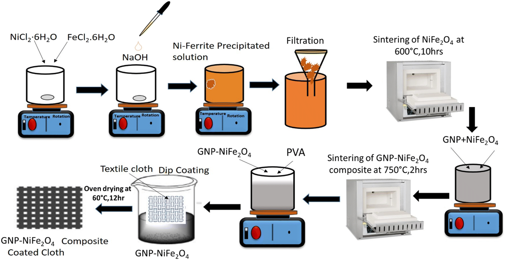 | ||
| Fig. 1 Synthesis of the GNP–NiFe2O4 composite and formulation process of paste for coating on cloth. | ||
2.2. Textile bonding with GNP–NiFe2O4
Fig. 2 presents the FTIR absorbance spectra of the cotton/polyester mix textile, cotton textile, and both textiles coated with the GNP–NiFe2O4 composite. The presence of FTIR peaks at (2800–3000) cm−1 and (900–1700) cm−1 (ref. 21) confirms the presence of GNPs on both textiles.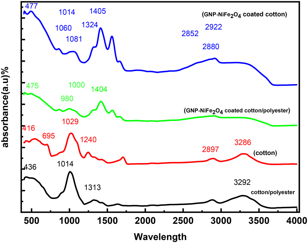 | ||
| Fig. 2 FTIR spectra of non-coated and coated textiles with the GNP–NiFe2O4 composite. | ||
Also, PVA peaks are observed in the range of (1300–1440) cm−1. The addition of PVA as a binder helps to bond the GNP–NiFe2O4 with cellulose (textile),22 whereas peaks for NiFe2O4 can be observed in the range of (400–700) cm−1 and a broader peak at (2800–2930) cm−1.
2.3. Fabrication of embroidered electrodes and the pressure sensor
To fabricate the embroidered electrodes, an embroidery machine from ZSK Stickmaschinen GmbH was employed. The sensor was designed using AutoCAD software and transformed into a digital stitch design file using the software GIS base Pac 10. The cotton thread was used as a bobbin, and the silver-tech 100 thread from Amann Group23 was threaded into the needle. To embroider the electrodes, the machine speed was set to 300 rpm. The bobbin thread tension was adjusted to 50 mN, while the top thread tension was set to 42 mN. A satin stich was used for embroidering the electrodes, with a minimum stitch length of 2 mm and a maximum stitch length of 4 mm. We embroidered an 8 finger interdigitated electrodes (IDEs) on the textile, which served as our base layer. The distance between fingers is 2 mm, and the width of each finger is also 2 mm. The length of each finger is 10 mm. The next layer, the GNP–NiFe2O4 coated textile, is the dielectric layer with a width of 1.5 cm and a length of 3.5 cm, and the final layer of polyethylene terephthalate (PET) is added as a sealing layer to complete the capacitive pressure sensor.In total, six combinations of graphene percentages and basic textiles were used. The six types of sensors were labeled as follows: cotton/polyester textile (S1), cotton/polyester textile 5% GNP–NiFe2O4 (S2), cotton/polyester textile 10% GNP–NiFe2O4 (S3), cotton (S4), cotton 5% GNP–NiFe2O4 (S5), and cotton 10% GNP–NiFe2O4 (S6). Table 1 shows the sensor design for different combinations of coated materials.
| Sensor | Textile description | Coating material | Size |
|---|---|---|---|
| S1 | Cotton/polyester mix | No | 1.5 × 3.5 cm |
| S2 | Cotton/polyester mix | 5 wt% GNP–NiFe2O4 | |
| S3 | Cotton/polyester mix | 10 wt% GNP–NiFe2O4 | |
| S4 | Cotton | No | |
| S5 | Cotton | 5 wt% GNP–NiFe2O4 | |
| S6 | Cotton | 10 wt% GNP–NiFe2O4 |
The dimensions of interdigitated electrodes (IDEs), embroidered structures, and coated textiles are shown in Fig. 3.
 | ||
| Fig. 3 Development and testing of pressure sensors: (a) sensor design with dimensions, (b) embroidered electrodes on the textile with a silver thread, (c) cotton and cotton/polyester mix textile, (d) cotton and cotton/polyester mix textile coated with GNP–NiFe2O4, (e) final sensor, coated textile attached with embroidered electrodes and sealed with PET, and (f) experimental setup to record the capacitance change due to a variation in applied pressure. | ||
2.4. Measurements
The sensor testing for applied compressive forces was done using an Instron 34SC-2. The output data were collected by connecting a Keysight handheld LCR meter (U1733C) to the pressure sensor. The detailed experimental setup is shown in Fig. 3(f). The textile coating was confirmed by images obtained using a JEOL JSM-6460 scanning electron microscope (SEM).3. Results and discussion
3.1. Morphological analysis of textiles coated with GNP–NiFe2O4
X-ray diffraction (XRD) analysis (Fig. S1†) revealed well-defined diffraction peaks corresponding to the (220), (311), (222), (400), (422), (511), and (440) planes, all of which are characteristic reflections of the cubic spinel structure of face-centered cubic (fcc) nickel ferrite. These reflections are intense and display slight peak broadening, indicative of the nanocrystalline nature of the synthesized material. No secondary phases were observed, confirming the phase purity of the nickel ferrite. The average crystallite size, along with d-spacing and dislocation density, was calculated and is summarized in Table S1.† Using the Debye–Scherrer equation, the average crystallite size was found to be approximately 110 nm. This relatively small crystallite size is particularly advantageous for capacitive sensor applications, as it contributes to an increased surface area and enhanced interfacial interactions—both critical for improving sensitivity and charge storage capability. The morphology of pure and mixed cotton-coated fabric with 5% and 10% loaded GNPs within a matrix of NiFe2O4/PVA polymer was characterized using SEM, as shown in Fig. 4(a–c) for cotton textiles and Fig. 4(d–f) for cotton/polyester textiles. Fig. 4(a) and (d) present the images of non-coated textiles. It is evident that both textiles are porous and rough. Fig. 4(b and c) show the coating of GNP–NiFe2O4 with 5% and 10% concentrations of GNPs on the cotton textile, respectively. The loading concentration has a prominent effect on the coating. Hence, the morphological analysis of textiles (cotton and cotton/polyester) coated with GNP–NiFe2O4 composites showed significant differences in the surface texture of the coated textiles at various concentrations of GNPs. In Fig. 4(e) and (f), the polyester/cotton textile coated with 5% and 10% GNP–NiFe2O4 is shown. Again, the increase in the GNP concentration can be seen as a denser and smoother coated textile in Fig. 4(f). In general, SEM images showed that higher concentrations of GNPs (10% by weight) resulted in denser and more uniform coatings. This densification is critical in enhancing the electrical connectivity across the fabric. This electrical connectivity has a direct impact on the sensitivity of capacitive sensors.24 Moreover, excellent adhesion to textiles was observed at the higher loading of GNPs. This adhesion between the coating and fabrics is the result of the large surface area of GNPs. There are no visible interfacial defects in the coated fabrics, which shows that GNPs are distributed more uniformly and could improve the electrical and mechanical properties of the textiles coated with GNP–NiFe2O4. | ||
| Fig. 4 SEM images of: (a) cotton textile, (b) cotton textile coated with 5% GNP–NiFe2O4, (c) cotton textile coated with 10% GNP–NiFe2O4, (d) cotton–polyester textile, (e) cotton–polyester textile coated with 5% GNP–NiFe2O4, (f) cotton/polyester textile coated with 10% GNP–NiFe2O4. | ||
Fig. 5(a–c) present the cross-sectional view of the cotton textile, whereas Fig. 5(d–f) show the same for the polyester/cotton textile. Fig. 5(a) and (d) show the cross-sectional images of the non-coated cotton and polyester/cotton textiles, respectively. The initial non-coated textile thickness ranges from 300 μm to 400 μm. Fig. 5(b), (c), (e) and (f) show the coated cotton and polyester/cotton textiles with varying concentrations of GNPs. Slight variations can be seen in the coating thickness due to the rough and porous structure of the textile. The maximum thickness was observed for the polyester/cotton textile coated with 10 wt% GNP–NiFe2O4 in the range of 534–582 μm.
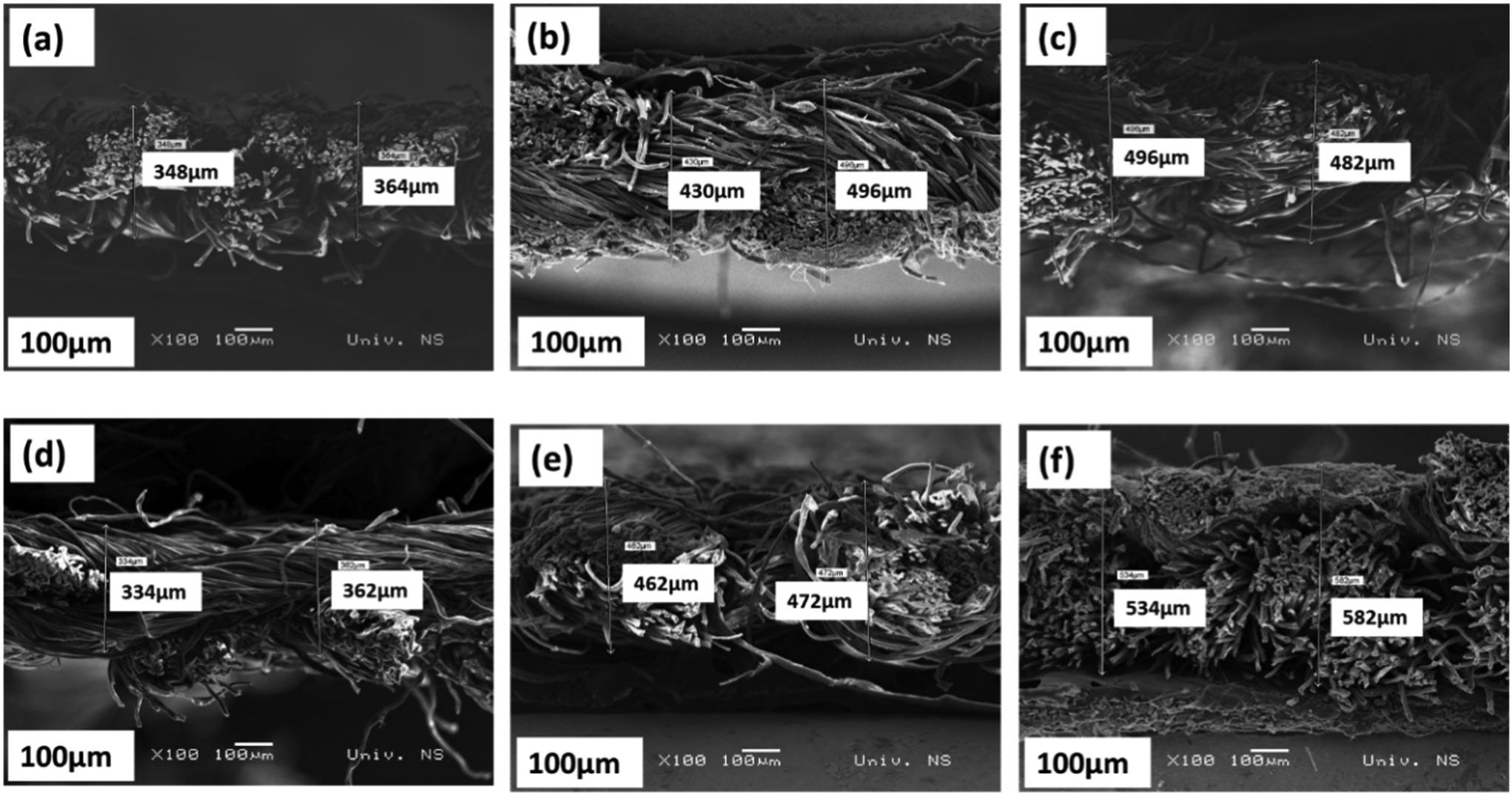 | ||
| Fig. 5 Cross sectional SEM images of the: (a) cotton textile, (b) cotton textile coated with 5% GNP/NiFe2O4, (c) cotton textile coated with 10% GNP–NiFe2O4, (d) cotton/polyester mix textile, (e) cotton/polyester mix textile coated with 5% GNP–NiFe2O4, and (f) cotton/polyester mix textile coated with 10% GNP–NiFe2O4. | ||
Before coating the GNP–NiFe2O4 composite on the textile, XRD and SEM analyses of GNPs, synthesized NiFe2O4 nanoparticles, and GNP–NiFe2O4 composites were performed to confirm the phase and morphology of platelets, nanoparticles and composites, respectively. The data are presented in ESI† data S1. The results show the successful synthesis of GNPs, synthesized NiFe2O4 nanoparticles, and GNP–NiFe2O4 composites (Fig. S1†) and the uniform distribution of the synthesized NiFe2O4 nanoparticles on GNPs (Fig. S2†).
3.2. Capacitance variation with applied pressure
Fig. 6 shows the capacitive response of a GNP composite-coated textile used as a dielectric layer by varying the GNP concentration and applied pressure. | ||
| Fig. 6 (a) Capacitive pressure sensor response under applied pressure for cotton and cotton/polyester mix textiles coated with different concentrations of GNPs, (b) relative change in capacitance with respect to applied pressure, (c) sensitivity changes in capacitive pressure sensors with respect to applied pressure, and (d) the linear response of the capacitor at different regions of applied pressure. | ||
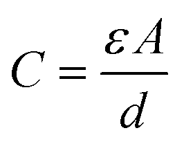
A noticeable increase in capacitance was observed in both cotton and polyester/cotton fabrics coated with 10 wt% GNP–NiFe2O4. Among these, the 10% GNP–NiFe2O4-coated polyester/cotton textile yielded the highest capacitance value, approximately 380 pF at a pressure of 333 kPa. This behavior can be explained by the compression-induced reduction in pore size within the dielectric layer, and the overall thickness of the dielectric layer enhancing its pressure-responsive characteristics as presented in Fig. S3.† This phenomenon can also be interpreted using the parallel plate capacitor model, as described by the capacitance equation (eqn (1)):
 | (1) |
Additionally, due to deformation, the internal fillers, such as nickel ferrites and GNPs, also overlap more closely with one another, increasing the local filler concentration. The dielectric constant of the system rises with increasing filler content according to the percolation theory, as a network is formed in the polymer matrix when GNPs join the ferrite nanoparticles. This mechanism results in linearity in the sensors.25,26 Researchers27 observed a similar trend in their research on textile-based sensors, where they achieved ultrahigh sensitivity by optimizing the nanowire density within the fabric matrix, demonstrating the critical role of material composition in sensor performance. Another reason for the greater change in capacitance for mixed textiles could be the difference in dielectric constants between cotton and polyester. The reported values in the literature are 1.60 and 1.90 for cotton and polyester, respectively.28 When pressure is applied, the response of the cotton/polyester mixed textile coated with the 10% GNP composite to pressure is observed in terms of the highest capacitance change. The change in capacitance with pressure in a dielectric layer made of the graphene nanoplatelet/nickel ferrite coated textile can also be explained by the piezo-capacitive effect. When compressive forces are applied to the sensor, mechanical deformation leads to a change in the distance between the conductive graphene nanoplatelets within the nickel ferrite matrix. This alteration in distance affects the dielectric constant of the material by changing the alignment and distribution of charges, which directly influences the capacitance.29 From the above results, our optimized sample is cotton/polyester textile 10 wt% GNP–NiFe2O4, which has the highest capacitance with respect to the applied pressure.
3.3. Sensitivity model of the textile-embroidered pressure sensor
The sensitivity and sensing range of a sensor can be used to determine its performance. Increasing the shift in capacitance within a specific pressure range was the primary method used to improve sensitivity. The sensitivity (S) of the capacitance sensor is defined as: | (2) |
The capacitance response in Fig. 6(b) shows the relative change in capacitance for the different pressure regions to optimize the final sample with maximum change in capacitance as compared to the other samples. Fig. 6(c) shows the sensitivity of all the samples with respect to pressure. The maximum sensitivity was approximately 0.4 kPa−1, 0.25 kPa−1 and 0.15 kPa−1 at 11.11 kPa for S3, S6 and S2, respectively, and it decreased as the pressure increased. Above 200 kPa, we observed the saturation region of the sensor. The sensitivity was not affected by a further increase in pressure; thus, the sensitivity is minimal in the region >200 kPa. S3 shows maximum sensitivity and capacitance change, therefore, the model equation was applied to this sample as shown in Fig. 6(d). The dual sensitivity is characteristic of pressure sensors, which could be explained by the mechanical compression of the fabric structure, which reduces the effective porosity of the fabric. The same phenomenon was observed by researchers,30 where the piezo-capacitive behavior of graphene-infused fabrics showed low sensitivity at higher pressures, and vice versa, due to the saturation of the deformation space. The coated textile dielectric layer filled the space between the electrode pairs when the sensor was under pressure. The dielectric layer fills the gaps more fully the higher the loading pressure. This caused the dielectric constant between the two electrodes to rise, which clearly altered the capacitance of the coated textile dielectric layer filling the space between the electrode pairs when the sensor was under pressure. For the GNP–NiFe2O4 composite dielectrics, the sensitivity of pressure sensors is influenced by the dielectric properties of the composite.31 This is because GNPs have high electrical conductivity and large surface area, which contributes to the overall dielectric response when pressure is applied.32
An IDE behaves like many sensors connected in parallel, which results in a significant increase in the capacitance of the sensor.33Fig. 6(d) present the fitted curve for three different regions of the pressure sensor. In contrast to the majority of previously reported pressure sensors, this one has a number of linear sensing ranges that correlate to various sensitivities and our results are consistent with these findings.34,35 The highest sensitivity is 0.13 kPa−1 in the pressure range of 11 kPa to 100 kPa, whereas a lower sensitivity of 0.05 kPa−1 and 0.02 kPa−1 is observed in the pressure range of 111 kPa to 166 kPa and >200 kPa, respectively. The comparison of current research with reported research is summarized in Table 2.
| Conductive electrodes | Dielectric | Sensitivity (kPa−1) | Pressure range | Ref. |
|---|---|---|---|---|
| Knitted | Elastomer of porous silicone | 0.0121 | 0–1 MPa | 36 |
| Nylon fabric | Ecoflex | 0.035 | 0–16 kPa | 37 |
| Cloth tape | Porous PDMS | 0.023 | >200 kPa | 38 |
| Carbonized cotton textile | Porous Ecoflex | 0.0245 | 0–1 MPa | 39 |
| Single-walled carbon nanotubes/silver paste/spacer fabric | Encapsulation/polyethylene terephthalate (PET) yarn layers | 0.042 | 1000kP | 40 |
| Silver fiber | Cotton fibers | 0.0397 | 0–200 kPa | 41 |
| Au | PVDF@AgNWs@TiO2 composite films | 0.0012 | 0–1500 kPa | 42 |
| Silver threads embroidered on cotton textile | Textile coated with GNP–NiFe2O4 | 0.13 | (11–100) kPa | Present work |
As can be seen, the present pressure sensors are fully textile based and easy to fabricate, and the sensitivity is higher than the reported textile-based pressure sensors. The sensor response can be modelled with the linear curves for three regions with an almost perfect fit (R2 = 0.98, 0.99 and 0.99, respectively), where SL1, SL2 and SL3 are the slopes of linear curves of the three regions.
3.4. Loading–unloading response of the textile-embroidered pressure sensor
To understand the mechanical qualities and mechanical stability of the optimized textile-embroidered pressure sensor in detail, a series of compressive experiments were conducted on 10% GNP–NiFe2O4 (sample S3, from Table 1). The process time of the constructed sensor under various stimulations is shown in Fig. 7(a), which indicates good synchronism. When considering its application as a flexible electronic device, this aspect is also a crucial one that must be taken into consideration. The process shows a gradual surge in pressure from 0 to 333 kPa, which proves the typical capacitive response under pressure. The initial capacitance of the optimized sensor is ∼16 pF, and the maximum capacitance is ∼381 pF at 333.33 kPa. When the external pressure increases stepwise, the corresponding capacitance also changes. After 333.33 kPa, when the pressure is released from the sensor, it drops to the initial state that proves the temporary deformation in the GNP–NiFe2O4 coated textile. Fig. 7(b) demonstrates the response assessment of the sensor beginning at no loading and increasing steps. It is noted that the capacitor's input and output signals, which exhibit a stepwise increasing trend as pressure increases, are reasonably robust under the test pressure. Numerous loading response tests confirmed that the capacitance response was likewise extremely stable at pressure loading and that the response had good storability when pressure was withdrawn.34 This demonstrates a stable response during the loading of the pressure and returns to zero after the removal of pressure, indicating excellent recoverability of the GNP–NiFe2O4 composite textile.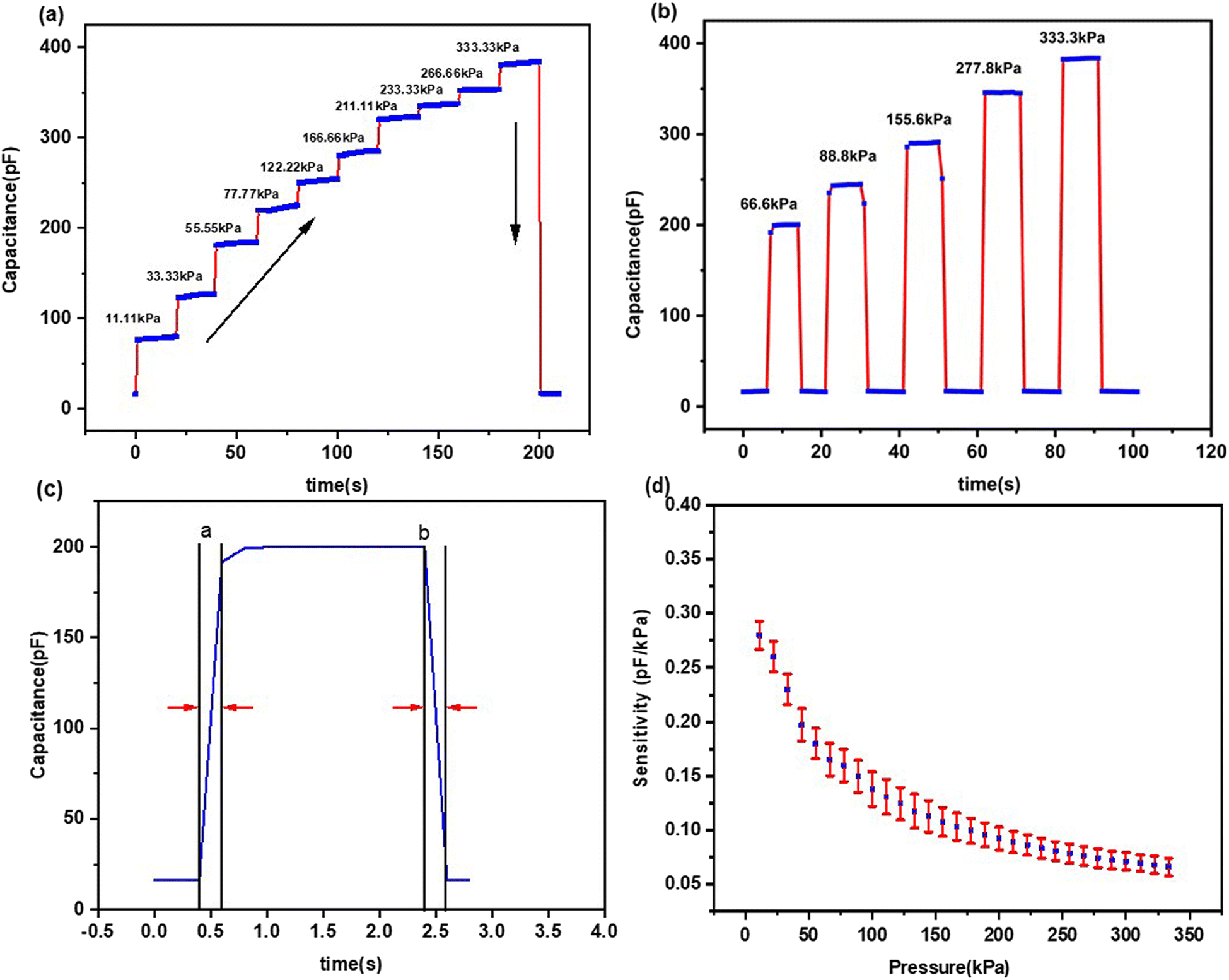 | ||
| Fig. 7 The capacitive response of the sensor under: (a) step loading and (b) loading and unloading, (c) response and recovery time, and (d) sensitivity of five sensors under applied pressure, representing the average and spread. | ||
The dynamic response of the sensor was further explored by means of the response and recovery time. Using the measured values from Fig. 7(b) for an applied pressure of 66 kPa, the response time was calculated as the time needed for the sensor to reach 90% of its final capacitance after applying the pressure, while the recovery time was determined as the time interval needed for the sensor to drop 90% of its initial capacitance after releasing the pressure. Fig. 7(c) shows the response and recovery time of the sensor under 66.6 kPa. The obtained values for response and recovery times are 0.2 s, which shows excellent recovery of the fabricated sensors. Hence, it can be concluded that our sensors demonstrated excellent mechanical stability and recoverability which are crucial to wearable applications where the sensor must withstand various mechanical stresses without permanent deformation.
A repeatability test for sensitivity was also conducted for the optimized pressure sensor S3 (10 wt% cotton/polyester textile). Five identical sensors were fabricated and tested for the sensitivity. Fig. 7(d) presents the sensitivity test results. The mean standard deviation for the sensitivity was 0.012 with a minimum and maximum standard deviation of 0.008 and 0.016. The stability test of the sensors has also been conducted by measuring capacitance change during different times of the day, as presented in Fig. S4.†
3.5. Finger tapping test
The finger tapping test is applied to recognize sensory motor disorder in fine motor skills. It is a symptom of neurological disorders such as autism, epilepsy, and Parkinson's disease. The routine method applied in clinics is the finger tapping test (FTT).43 In this test, the finger tapping of the patient is recorded for taps per minute. The fine motor speed is tracked through the average number of taps, and performance differences over time track the progress or regression of the disease.44Fig. 8 presents the finger tapping test of a normal person. Fig. 8(a) shows the index finger tapping test and Fig. 8(b) presents the all finger tapping test. In the finger tapping test, we measured the capacitive response of the sensor over a 10 second interval. The recorded data show an average tapping frequency of 2.5 Hz, corresponding to 25 taps in 10 seconds, with each tap displacing 1 cm with pauses for approximately 5 seconds. As shown in Fig. 8(a), the capacitance exhibited periodic fluctuations corresponding to the finger motion. In Fig. 8(b), the subject was asked to tap the sensor for 15 seconds, from the thumb to little finger, and finally with the index finger and thumb together. | ||
| Fig. 8 Testing of the sensor by tapping with (a) the index finger and (b) all fingers of the right hand. | ||
The fine motor speed is monitored through the average number of taps, and the performance difference can be tracked over time to monitor progress or regression.44 At present, the FTT is recorded through manual counting, which is then processed using computer vision algorithms. These sensors can be integrated with gloves to monitor the finger motion for any kind of motor skill disorder and repetitive behavior.
4. The portable measurement system with the smartphone-based application
We also developed a smartphone application for data collection and presentation of results, as shown in Fig. 9. To increase the portability and wearability of the developed system, we also implemented a microcontroller-based system for capacitance measurement and data transfer to a smartphone. The measurement system has two microcontroller boards: Arduino Nano Every for capacitance measurement and Arduino Nano BLE 33 Sense for data transfer to the mobile phone. The communication between the two microcontroller boards is over UART (universal asynchronous receiver/transmitter). The application was developed using the MIT App Inventor. The sensor readings shown on the screen of the application are the values obtained when the initial baseline capacitance (at the system startup) is subtracted from the current measurement. Therefore, the change in capacitance is shown. Because of this, when the sensor is not pressed, the screen will show a value of zero. With this approach, we emphasized the change in capacitance caused by pressing the sensor. The functionality was verified on Android 11-based smartphone. The communication between the application installed on the smartphone and the measurement system is based on Bluetooth Low Energy (BLE) which can be visualized in a video attached in the ESI† (S2). | ||
| Fig. 9 Screenshot of the developed application: (a) android app, (b) sensor connection to Arduino Nano BLE 33 Sense, (c) real response of the sensor displayed on a mobile phone via Bluetooth. | ||
The key points of the current research are: (i) the pressure sensor is developed by utilizing a cost-effective embroidery technique; (ii) the pressure sensor can be attached to the body by embedding into t-shirts. It would be helpful for continuous and real-time monitoring of any external pressure on the skin or body part; (iii) if the wearer faces any kind of physical attack, a timely alert can be sent to rescuers if pressure levels cross the threshold level, enabling timely intervention.
5. Conclusion
In this work, an interdigitated textile-based pressure sensor was fabricated by utilizing an embroidery technique, while a promising nanocomposite of GNP–NiFe2O4 was employed as the dielectric layer for wireless technology applications. Our results revealed that due to the larger contact area, the capacitive layer embedded in the interdigitated structure demonstrated a significant capacitance shift of 16 pF to 381 pF. The sensor sensitivity varied with the concentration of the coated material and the type of textile. The highest sensitivity was observed for the cotton mix cloth coated with 10% GNP–NiFe2O4. The impact of various fabric types when utilized as a dielectric material was further investigated and it was observed that polyester mixed cotton had the highest response under applied pressure compared to other cotton fabrics coated with 10 wt% GNP–NiFe2O4. It is anticipated that these flexible pressure sensors can be used in a variety of smart textile-based applications, such as facilitating the progress of fine motor skills through the finger tapping test, which can also be managed via Bluetooth technology on mobile devices.Data availability
The datasets generated during the current research are available from the corresponding author upon reasonable request.Author contributions
A. A. and S. Q. conceived the presented idea. A. A.: material synthesis, characterization, writing and review. S. Q.: sensor fabrication, data collection, application, writing and review. M. S.: electronics design, mobile application, writing and review. H. A. M.: review and editing. S. G.: review and editing. F. L. D.: supervision. G. M. S.: supervision, review, editing, and fund collection. All authors discussed the results and contributed to the final manuscript.Conflicts of interest
The authors declare that no competing interests exist.Acknowledgements
This research was funded through the Horizon Europe Framework Programme of European Commission, under grant agreement No. 101086348 as well as S. Q., M. S., G. M. S. would like to thank STRENTEX project no 854194 for support. The authors would like to thank the group of Snežana Vučetić from the Faculty of Technology, the University of Novi Sad, for performing FTIR.References
- S. Sharma, A. Chhetry, M. Sharifuzzaman, H. Yoon and J. Yeong Park, Wearable Capacitive Pressure Sensor Based on MXene Composite Nanofibrous Scaffolds for Reliable Human Physiological Signal Acquisition, ACS Appl. Mater. Interfaces, 2020, 12(19), 22212–22224 CrossRef CAS PubMed.
- Y. Xiong, Y. Shen, L. Tian, Y. Hu, P. Zhu and R. Sun, et al., A flexible, ultra-highly sensitive and stable capacitive pressure sensor with convex microarrays for motion and health monitoring, Nano Energy, 2020, 70, 104436 CrossRef CAS.
- S. R. A. Ruth, L. Beker, H. Tran, V. R. Feig, N. Matsuhisa and Z. Bao, Rational design of capacitive pressure sensors based on pyramidal microstructures for specialized monitoring of biosignals, Adv. Funct. Mater., 2020, 30(29), 1903100 CrossRef CAS.
- Y. Luo, J. Shao, S. Chen, X. Chen, H. Tian and X. Li, et al., Flexible capacitive pressure sensor enhanced by tilted micropillar arrays, ACS Appl. Mater. Interfaces, 2019, 11(19), 17796–17803 CrossRef CAS PubMed.
- X. Shuai, P. Zhu, W. Zeng, Y. Hu, X. Liang and Y. Zhang, et al., Highly sensitive flexible pressure sensor based on silver nanowires-embedded polydimethylsiloxane electrode with microarray structure, ACS Appl. Mater. Interfaces, 2017, 9(31), 26314–26324 CrossRef CAS PubMed.
- J. Hwang, Y. Kim, H. Yang and J. H. Oh, Fabrication of hierarchically porous structured PDMS composites and their application as a flexible capacitive pressure sensor, Composites, Part B, 2021, 211, 108607 CrossRef CAS.
- O. Atalay, A. Atalay, J. Gafford and C. Walsh, A highly sensitive capacitive-based soft pressure sensor based on a conductive fabric and a microporous dielectric layer, Adv. Mater. Technol., 2018, 3(1), 1700237 CrossRef.
- J. Choi, D. Kwon, K. Kim, J. Park, D. Del Orbe and J. Gu, et al., Synergetic effect of porous elastomer and percolation of carbon nanotube filler toward high performance capacitive pressure sensors, ACS Appl. Mater. Interfaces, 2019, 12(1), 1698–1706 CrossRef PubMed.
- D. Kwon, T. I. Lee, J. Shim, S. Ryu, M. S. Kim and S. Kim, et al., Highly sensitive, flexible, and wearable pressure sensor based on a giant piezocapacitive effect of three-dimensional microporous elastomeric dielectric layer, ACS Appl. Mater. Interfaces, 2016, 8(26), 16922–16931 CrossRef CAS.
- Y. Long, X. Zhao, X. Jiang, L. Zhang, H. Zhang and Y. Liu, et al., A porous graphene/polydimethylsiloxane composite by chemical foaming for simultaneous tensile and compressive strain sensing, FlatChem, 2018, 10, 1–7 CrossRef CAS.
- Y. Kim, S. Jang and J. H. Oh, Fabrication of highly sensitive capacitive pressure sensors with porous PDMS dielectric layer via microwave treatment, Microelectron. Eng., 2019, 215, 111002 CrossRef.
- O. Akman, H. Kavas, A. Baykal, M. S. Toprak, A. Çoruh and B. Aktaş, Magnetic metal nanoparticles coated polyacrylonitrile textiles as microwave absorber, J. Magn. Magn. Mater., 2013, 327, 151–158 CrossRef CAS.
- S. Shahidi, Magnetic nanoparticles application in the textile industry—A review, J. Ind. Text., 2021, 50(7), 970–989 CrossRef.
- C. E. Stroe and R. M. Aileni, An overview on nanomaterials with magnetic properties used in the textile sector, Ind. Text., 2022, 73(3), 317–326 Search PubMed.
- M. Li, Y. T. Li, D. W. Li and Y. T. Long, Recent developments and applications of screen-printed electrodes in environmental assays—A review, Anal. Chim. Acta, 2012, 734, 31–44 CrossRef CAS PubMed.
- N. W. Solís Pinargote, A. Smirnov, N. Peretyagin, A. Seleznev and P. Peretyagin, Direct ink writing technology (3D printing) of graphene-based ceramic nanocomposites: A review, Nanomaterials, 2020, 10(7), 1300 CrossRef.
- V. Orts Mercadillo, K. C. Chan, M. Caironi, A. Athanassiou, I. A. Kinloch and M. Bissett, et al., Electrically conductive 2D material coatings for flexible and stretchable electronics: a comparative review of graphenes and MXenes, Adv. Funct. Mater., 2022, 32(38), 2204772 CrossRef CAS.
- Y. Wang, T. Hua, B. Zhu, Q. Li, W. Yi and X. Tao, Novel fabric pressure sensors: design, fabrication, and characterization, Smart Mater. Struct., 2011, 20(6), 065015 CrossRef.
- J. w. Zhang, Y. Zhang, Y. y. Li and P. Wang, Textile-based flexible pressure sensors: A review, Polym. Rev., 2022, 62(1), 65–94 CrossRef CAS.
- S. Javaid, A. Mahmood, H. Nasir, M. Iqbal, N. Ahmed and N. M. Ahmad, Layer-by-layer self-assembled dip coating for antifouling functionalized finishing of cotton textile, Polymers, 2022, 14(13), 2540 CrossRef CAS PubMed.
- B. Zhang and T. Chen, Study of ultrasonic dispersion of graphene nanoplatelets, Materials, 2019, 12(11), 1757 CrossRef CAS PubMed.
- S. Çaylak, O. Demirel, M. Javadzadehkalkhoran, A. Navidfar, M. Yaşacan and L. Trabzon, Preparation and characterization of high-performance water-based graphene dispersions for conductive coating on textiles, J. Text. Inst., 2025, 116(3), 446–454 CrossRef.
- Special conductive thread by AMANN: Silver-tech+ [Internet]. [cited 2021 Nov 19], Available from: https://www.amann.com/products/product/silver-tech-plus/.
- Y. Zhou, C. Zhang, C. Myant and R. Stewart, Knitted Graphene Supercapacitor and Pressure-Sensing Fabric, Eng. Proc., 2022, 15(1), 5 Search PubMed.
- Y. Shi, X. Lü, J. Zhao, W. Wang, X. Meng and P. Wang, et al., Flexible capacitive pressure sensor based on microstructured composite dielectric layer for broad linear range pressure sensing applications, Micromachines, 2022, 13(2), 223 CrossRef PubMed.
- Z. Ma, K. Zhang, S. Yang, Y. Zhang, X. Chen and Q. Fu, et al., High-performance capacitive pressure sensors Fabricated by introducing dielectric filler and conductive filler into a porous dielectric layer through a Biomimic strategy, Compos. Sci. Technol., 2022, 227, 109595 CrossRef CAS.
- Y. Lian, H. Yu, M. Wang, X. Yang and H. Zhang, Ultrasensitive wearable pressure sensors based on silver nanowire-coated fabrics, Nanoscale Res. Lett., 2020, 15, 1–8 CrossRef PubMed.
- S. Sankaralingam and B. Gupta, Determination of dielectric constant of fabric materials and their use as substrates for design and development of antennas for wearable applications, IEEE Trans. Instrum. Meas., 2010, 59(12), 3122–3130 CAS.
- S. Sharma, A. Verma, S. M. Rangappa, S. Siengchin and S. Ogata, Recent progressive developments in conductive-fillers based polymer nanocomposites (CFPNC's) and conducting polymeric nanocomposites (CPNC's) for multifaceted sensing applications, J. Mater. Res. Technol., 2023, 26, 5921–5974 CrossRef CAS.
- D. Sengupta, L. Lu, Y. Pei and A. G. P. Kottapalli, Fabric-Like Pvac-Graphene Nanofiber Capacitive Pressure Sensors For Next-Generation Wearables, in 2022 IEEE 35th International Conference on Micro Electro Mechanical Systems Conference (MEMS), IEEE, 2022, pp. 341–344 Search PubMed.
- H. M. Yadav, N. C. Deb Nath, J. Kim, S. K. Shinde, S. Ramesh and F. Hossain, et al., Nickel-Graphene nanoplatelet deposited on carbon fiber as binder-free electrode for electrochemical supercapacitor application, Polymers, 2020, 12(8), 1666 CrossRef CAS PubMed.
- A. Soam, R. Kumar, D. Thatoi and M. Singh, Electrochemical performance and working voltage optimization of nickel ferrite/graphene composite based supercapacitor, J. Inorg. Organomet. Polym. Mater., 2020, 30(9), 3325–3331 CrossRef CAS.
- R. Qin, M. Hu, X. Li, T. Liang, H. Tan and J. Liu, et al., A new strategy for the fabrication of a flexible and highly sensitive capacitive pressure sensor, Microsyst. Nanoeng., 2021, 7(1), 100 CrossRef CAS PubMed.
- A. Chhetry, S. Sharma, H. Yoon, S. Ko and J. Y. Park, Enhanced sensitivity of capacitive pressure and strain sensor based on CaCu3Ti4O12 wrapped hybrid sponge for wearable applications, Adv. Funct. Mater., 2020, 30(31), 1910020 CrossRef CAS.
- L. Huang, H. Wang, D. Zhan and F. Fang, Flexible capacitive pressure sensor based on laser–induced graphene and polydimethylsiloxane foam, IEEE Sens. J., 2021, 21(10), 12048–12056 CAS.
- O. Atalay, A. Atalay, J. Gafford and C. Walsh, A highly sensitive capacitive-based soft pressure sensor based on a conductive fabric and a microporous dielectric layer, Adv. Mater. Technol., 2018, 3(1), 1700237 CrossRef.
- R. Wu, L. Ma, A. Balkrishna Patil, C. Hou, Z. Meng and Y. Zhang, et al., A facile method to prepare a wearable pressure sensor based on fabric electrodes for human motion monitoring, Text. Res. J., 2019, 89(23–24), 5144–5152 CrossRef CAS.
- S. Li, K. Dong, R. Li, X. Huang, T. Chen and X. Xiao, Capacitive pressure sensor inlaid a porous dielectric layer of superelastic polydimethylsiloxane in conductive fabrics for detection of human motions, Sens. Actuators, A, 2020, 312, 112106 CrossRef CAS.
- Y. Ko, C. C. Vu and J. Kim, Carbonized cotton fabric-based flexible capacitive pressure sensor using a porous dielectric layer with tilted air gaps, Sensors, 2021, 21(11), 3895 CrossRef CAS PubMed.
- C. C. Vu and J. Kim, Highly elastic capacitive pressure sensor based on smart textiles for full-range human motion monitoring, Sens. Actuators, A, 2020, 314, 112029 CrossRef CAS.
- Q. Zhang, Y. L. Wang, Y. Xia, P. F. Zhang, T. V. Kirk and X. D. Chen, Textile-only capacitive sensors for facile fabric integration without compromise of wearability, Adv. Mater. Technol., 2019, 4(10), 1900485 CrossRef.
- R. Han, Y. Liu, Y. Mo, H. Xu, Z. Yang and R. Bao, et al., High anti-jamming flexible capacitive pressure sensors based on core–shell structured AgNWs@TiO2, Adv. Funct. Mater., 2023, 33(51), 2305531 CrossRef CAS.
- D. Austin, J. McNames, K. Klein, H. Jimison and M. Pavel, A statistical characterization of the finger tapping test: modeling, estimation, and applications, IEEE J. Biomed. Health Inform., 2014, 19(2), 501–507 Search PubMed.
- J. Son, A. Ra Ko, Y. H. Lee and Y. Kim, A computer-based finger-tapping system for evaluating movement of the affected hand following stroke: A pilot study, Int. J. Precis. Eng. Manuf., 2012, 13, 2083–2086 CrossRef.
Footnote |
| † Electronic supplementary information (ESI) available. See DOI: https://doi.org/10.1039/d5sd00046g |
| This journal is © The Royal Society of Chemistry 2025 |