DOI:
10.1039/D4SC07619B
(Edge Article)
Chem. Sci., 2025,
16, 4806-4814
Controlling electrocatalytic nitrate reduction efficiency by utilizing dπ–pπ interactions in parallel stacking molecular systems†
Received
10th November 2024
, Accepted 11th January 2025
First published on 12th February 2025
Abstract
Electrochemical reduction of nitrate to ammonia using electrocatalysts is a promising alternative strategy for both wastewater treatment and production of green ammonia. Numerous tactics have been developed to increase the electrocatalyst's NO3RR activity. Herein, we report a unique molecular alignment-dependent NO3RR performance using α-CuPc and β-CuPc nanostructures as effective electrocatalysts for the ambient synthesis of ammonia. The well-aligned β-CuPc demonstrated an impressive ammonia yield rate of 62![[thin space (1/6-em)]](https://www.rsc.org/images/entities/char_2009.gif) 703 μg h−1 mgcat−1 and a Faradaic efficiency of 96%. In contrast, the less well-aligned α-CuPc exhibited a yield rate of 36889 μg h−1 mgcat−1 and a Faradaic efficiency of 61% at −1.1 V vs. RHE under the same conditions. Scanning tunneling microscopy/spectroscopy (STM/S) confirms that the well-aligned β-CuPc exhibits superior transport properties due to optimal interaction of the Cu atom with the nitrogen atom of parallel molecules (dπ–pπ) in its one-dimensional nanostructure, which is clearly reflected in the electrocatalytic performance. Furthermore, theoretical research reveals that the NO3RR is the predominant process on the β-CuPc catalyst in comparison to the hydrogen evolution reaction, which is verified by gas chromatography, with β-CuPc exhibiting weaker binding of the *NO intermediate at the copper site and a lower overpotential, hence facilitating the NO3RR relative to α-CuPc.
703 μg h−1 mgcat−1 and a Faradaic efficiency of 96%. In contrast, the less well-aligned α-CuPc exhibited a yield rate of 36889 μg h−1 mgcat−1 and a Faradaic efficiency of 61% at −1.1 V vs. RHE under the same conditions. Scanning tunneling microscopy/spectroscopy (STM/S) confirms that the well-aligned β-CuPc exhibits superior transport properties due to optimal interaction of the Cu atom with the nitrogen atom of parallel molecules (dπ–pπ) in its one-dimensional nanostructure, which is clearly reflected in the electrocatalytic performance. Furthermore, theoretical research reveals that the NO3RR is the predominant process on the β-CuPc catalyst in comparison to the hydrogen evolution reaction, which is verified by gas chromatography, with β-CuPc exhibiting weaker binding of the *NO intermediate at the copper site and a lower overpotential, hence facilitating the NO3RR relative to α-CuPc.
Introduction
Ammonia (NH3) has a high weight hydrogen storage capacity of 17.6% and a high energy density, making it a promising carbon-free energy carrier and a medium for the next generation of renewable energy storage.1 The electrocatalytic nitrate reduction reaction (NO3RR) is a greener substitute for the energy-intensive and ecologically polluting Haber–Bosch method for ammonia production.2–4 As a result, nitrate to ammonia conversion using renewable energy may accomplish both nitrate removal and ammonia synthesis, which is very relevant for balancing sustainability issues with benefits for the economy.5,6 The electrocatalytic reduction of nitrate to ammonia is a complex procedure that requires the transfer of eight electrons and nine protons, which results in a low ammonia production rate and Faradaic efficiency. This process is kinetically slow and impeded by the competing hydrogen evolution reaction.7,8 Consequently, it is imperative to identify effective catalysts to enhance the kinetics of the NO3RR. Diverse strategies have been investigated to enhance the efficacy of the electrocatalyst by improving its intrinsic reaction activity and selectivity for the reduction of nitrate to NH3. These strategies include defect engineering,9,10 alloying,11,12 the effect of dissolved oxygen,13 core–shell structures,14 crystal phase engineering,15 strain engineering,16 Janus structures,17 interface engineering,18 and oxygen vacancies19 and many more.20,21 Despite these advances, molecular alignment in nanostructure based electrocatalysts, which is one of the important parameters for selective nitrate-to-ammonia reduction, is rarely reported.
Transition metal phthalocyanine-based molecular structures have attracted considerable scientific attention because of their significant contributions to several catalytic applications, including photocatalysts,22 electrocatalytic oxidation,23,24 reduction processes,25–30 and others. Versatility in the activity of these metal complexes and their performance depends on the metal–ligand interaction, which depends on the alignment of the molecules within the crystal. Metal phthalocyanines are combinations of porphyrin derivatives with a core metallic atom attached to a π-conjugated ligand and aromatic molecules that may be stacked by π–π supramolecular interactions. The characteristics of these compounds are determined by their structure. The π–π stacking along with the aromaticity of phthalocyanine molecules provides excellent thermal and chemical stability. Due to the planar macrocyclic structure and the availability of π electrons, 1D growth of phthalocyanines is favourable through π–π interactions. Their excellent thermal stability, good electron response, flexibility and easy fabrication technique have endowed them with multifunctional applications.31 Most of the metal phthalocyanines exist in either triclinic or monoclinic polymorphism.32 The polymorphs of metal phthalocyanines depend on their arrangement of molecular macrocycles and the substrate surface–molecular interactions.33 Hence, charge carrier mobility and conductivity through π–π interactions in one-dimensional nanostructures, depending on molecular orientation, may influence the electrocatalytic performance. Among the metal phthalocyanine nanostructures, CuPc is a widely used molecule for fundamental and technological applications due to its semiconductor nature.31 CuPc crystallizes into four phases α, β, γ, and δ and α and β are the most stable phases. Within the herringbone structure of the two α and β phases, the molecules arrange themselves in stacks interconnected by van der Waals interactions. These stacks are oriented at angles of 26.5° and 45.8°, respectively, between the column direction (b-axis) and the molecular plane.34 Recently, Dutt et al.35 studied the geometry dependent electrocatalytic oxygen reduction reaction and hydrogen evolution properties using the regio-isomers of tetra-amino-substituted cobalt phthalocyanine. To our knowledge, there has yet to be a study focused on the molecular alignment dependent electrocatalyst nitrate reduction reaction.
We have fabricated α-CuPc and β-CuPc electrocatalysts, with β-CuPc exhibiting better alignment compared to α-CuPc and studied the electrocatalytic NO3RR. To understand the effect of the molecular alignment on the electrical conductivities for both the α-CuPc and β-CuPc, STM measurements were carried out, suggesting that the β-phase should have better transport properties compared to its α counterpart. We then investigated the impact of molecular alignment on the electrocatalytic performance of the nitrate reduction reaction (NO3RR). The sandwiched structured β-CuPc showed an ammonia yield rate of 62703 μg h−1 mgcat−1 and 96% Faradaic efficiency, whereas less well aligned α-CuPc showed a yield rate of 36889 μg h−1 mgcat−1 and 61% Faradaic efficiency at −1.1 V vs. RHE under ambient conditions. The overpotential (η) values at the Cu site of α-CuPc and β-CuPc are 0.72 eV and 0.48 eV, respectively, mostly dependent on the adsorption of the *NO intermediate. Consequently, β-CuPc demonstrates enhanced catalytic efficacy for the NO3RR.
Results and discussion
STM characterization for predicting electrocatalytic efficacy
The electrocatalytic performance of a material is strongly governed by its intrinsic electrical transport properties. Hence, before proceeding to the study of the molecular orientation dependent electrocatalysis properties of α- and β-phthalocyanines, we investigated their electrical transport properties, both at the nanoscale and in the bulk of the materials. In this regard, we first characterized the phthalocyanines through a localized mode of measurements namely scanning tunneling microscopy (STM). For such measurements, synthesized phthalocyanine samples dispersed in ethanol with vigorous sonication were drop-cast and dried on a freshly cleaved highly oriented pyrolytic graphite (HOPG) surface. In Fig. 1b, the STM topography of the fraction of phthalocyanines recorded in constant current mode has been presented. Although the diameter of the fraction of the β-phase was found to be higher than that of the α-phase, the results infer that both phthalocyanines have a nanowire kind of shape. We then proceeded to record the tunneling current vs. voltage (ITunneling–V) of the phthalocyanines at room temperature by positioning the tip over an individual phthalocyanine nanowire and momentarily disabling the feedback loop. Although a comparison of current at a particular voltage could provide a preliminary idea on the conductivities of α- and β-phthalocyanines, such analysis is not possible from STS, as the same tip–sample separation could not be ensured for both compounds. In this direction, to understand the transport properties, analysis of the transport gap would be a better approach. We could locate the band edges and transport gap of the phthalocyanines from STS as the differential tunnel conductance {(dI/dV)Tunneling} spectra reflect the density of states, (dI/dV)Tunneling ∝ DOS. Here, the work functions of the substrate electrode and tip are aligned at 0 V, and the band energies are determined with regard to Fermi energy (EF). The conduction band (CB) edge was shown by the first peak in the negative voltage region, which was the point at which electrons could be injected from the tip to the semiconductor, because the bias was provided to the tip with regard to the substrate electrode. In a similar vein, the valence band (VB) edge, which marks the point at which electrons can be extracted from phthalocyanines, was indicated by the first peak at the positive voltage. We observed a characteristically higher transport gap of the α-phase, resulting in inferior transport properties of the compound compared to the β-phase (Fig. 1d). It may be noted that a larger transport gap reflects higher carrier effective mass, leading to inferior transport due to the presence of fewer charge carriers available for conduction. Hence, a comparison of transport gaps suggests that the β-phase should have better transport properties compared to its α counterpart.
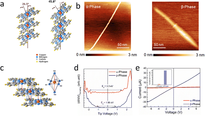 |
| | Fig. 1 (a) Schematic diagram of α-CuPc and β-CuPc. (b) STM topographies (recorded in constant current mode) of α- and β-phthalocyanines. (c) Schematic representation of intermolecular interaction in β-CuPc. (d) Differential tunnel conductance (dI/dV)Tunneling spectra of α- and β-phthalocyanines to understand their transport gap. (e) Current–voltage characteristics (I–V) of bulk α- and β-phthalocyanines as obtained from two-probe measurements. Inset shows a comparison of current at 4 V. All the results infer better transport properties of β-phthalocyanines. | |
To further validate these results, we carried out current–voltage (I–V) measurements in their bulk through a conventional two probe measurement. A higher current was witnessed in the β-phase (Fig. 1e) to conclusively state that the β-phase has better electrical transport properties. It would be anticipated that the unpaired 3d electrons of Cu will interact with the ligating nitrogen atoms at ∼1.83 Å. The molecule contains four additional nitrogen atoms spaced ∼3.38 Å apart in the same molecular structure.
In β-CuPc, the central Cu atom lies exactly over and under the nitrogen molecules of parallel molecules due to its angle of 45.8° with the b axis (Fig. 1a). The closest distance of parallel β-CuPc is ∼3.38 Å, which is the distance between intermolecular Cu and N (N4) (Fig. 1c). It is possible to think of the central Cu atom as being at the heart of a square-bonded structure inside a wider octahedral array of nitrogen atoms. It can also be considered a sandwiched structure with the Cu atom in the centre and nitrogen of the parallel molecule above and below Cu. But it may be deduced that the extra molecular nitrogen in the closest molecules does not form the complete nitrogen octahedron in the α-phase.36 These interactions of central Cu with nitrogen of the parallel molecule may play a vital role in enhancing the electrical transport of β-CuPc.
Structural characterization of α-CuPc and β-CuPc
X-ray diffraction (XRD) analysis was employed to assess the phase purity of the synthesized β-CuPc. The resulting XRD plot exhibits two prominent peaks at 6.9° and 9.1°, corresponding to the (![[1 with combining macron]](https://www.rsc.org/images/entities/char_0031_0304.gif) 01) and (101) planes of β-CuPc, respectively (Fig. 2a). Furthermore, all other minor peaks observed in the pattern are consistent with the reference pattern of β-CuPc (JCPDS data card no: 39-1881), confirming the successful formation of the desired β-CuPc phase. The formation of α-CuPc was confirmed by matching XRD with JCPDS card no 36-1883 (Fig. S1a†). X-ray photoelectron spectroscopy (XPS) was utilized to examine the elemental composition and the chemical state of atoms within the CuPc molecule. The survey spectrum in Fig. S2† confirms the presence of Cu, N, and C elements in CuPc. Notably, the N 1s peak can be deconvoluted into two distinct components (Fig. 2b), corresponding to the nitrogen atoms in different chemical environments: the iso-indole nitrogen bonded to the central copper atom at 399.1 eV and the azomethine nitrogen bridging the carbon atoms in the pyrrole rings at 397.7 eV.37 Furthermore, the Cu 2p spectrum (Fig. 2c) reveals peaks at 954.46 eV and 934.6 eV, assignable to the Cu 2p1/2 and Cu 2p3/2 electronic states, respectively. Additionally, a characteristic satellite peak is observed in the Cu 2p region, providing further insight into the electronic structure of the copper atoms within CuPc.38 There is no significant change in XPS spectra between both polymorphs of CuPc (Fig. S2 and S4†). The FT-IR spectrum in Fig. 2d reveals distinct peaks corresponding to the vibrational characteristic modes. The C
01) and (101) planes of β-CuPc, respectively (Fig. 2a). Furthermore, all other minor peaks observed in the pattern are consistent with the reference pattern of β-CuPc (JCPDS data card no: 39-1881), confirming the successful formation of the desired β-CuPc phase. The formation of α-CuPc was confirmed by matching XRD with JCPDS card no 36-1883 (Fig. S1a†). X-ray photoelectron spectroscopy (XPS) was utilized to examine the elemental composition and the chemical state of atoms within the CuPc molecule. The survey spectrum in Fig. S2† confirms the presence of Cu, N, and C elements in CuPc. Notably, the N 1s peak can be deconvoluted into two distinct components (Fig. 2b), corresponding to the nitrogen atoms in different chemical environments: the iso-indole nitrogen bonded to the central copper atom at 399.1 eV and the azomethine nitrogen bridging the carbon atoms in the pyrrole rings at 397.7 eV.37 Furthermore, the Cu 2p spectrum (Fig. 2c) reveals peaks at 954.46 eV and 934.6 eV, assignable to the Cu 2p1/2 and Cu 2p3/2 electronic states, respectively. Additionally, a characteristic satellite peak is observed in the Cu 2p region, providing further insight into the electronic structure of the copper atoms within CuPc.38 There is no significant change in XPS spectra between both polymorphs of CuPc (Fig. S2 and S4†). The FT-IR spectrum in Fig. 2d reveals distinct peaks corresponding to the vibrational characteristic modes. The C![[double bond, length as m-dash]](https://www.rsc.org/images/entities/char_e001.gif) N–C bonds at bridge sites showed characteristic peaks at 1288 cm−1 with an additional peak at 1334 cm−1 in CuPc.39 The sharp peak around 727 cm−1 corresponds to beta and the peak at 720 cm−1 corresponds to alpha polymorphs.40 UV-vis spectroscopy of α-CuPc showed the Soret band and Q band at 382 nm and 630 nm, respectively (Fig. S1b and c†), whereas for the β polymorph, the Soret band and Q band shifted to a longer wavelength of 450 nm and 653 nm, respectively, due to better interaction, as mentioned before.
N–C bonds at bridge sites showed characteristic peaks at 1288 cm−1 with an additional peak at 1334 cm−1 in CuPc.39 The sharp peak around 727 cm−1 corresponds to beta and the peak at 720 cm−1 corresponds to alpha polymorphs.40 UV-vis spectroscopy of α-CuPc showed the Soret band and Q band at 382 nm and 630 nm, respectively (Fig. S1b and c†), whereas for the β polymorph, the Soret band and Q band shifted to a longer wavelength of 450 nm and 653 nm, respectively, due to better interaction, as mentioned before.
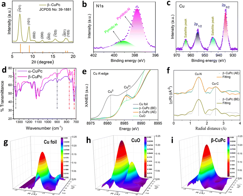 |
| | Fig. 2 (a) XRD plot of β-CuPc, (b) high resolution XPS N 1s spectra of β-CuPc, (c) high resolution XPS Cu 2p spectra of β-CuPc, (d) FTIR spectra of α-CuPc and β-CuPc, (e) Cu K-edge XANES spectra of β-CuPc before and after electrolysis, (f) EXAFS spectra of β-CuPc before and after electrolysis, and (g–i) wavelet-transform EXAFS plot of Cu foil, CuO and β-CuPc. | |
At the energy-scanning EXAFS beamline (BL-09) of the Indus-2 synchrotron source, XANES and EXAFS observations of the β-CuPc sample were conducted both before and after electrolysis. Fig. 2e shows the typical XANES spectra of β-CuPc recorded at the Cu K-edge, along with the metal Cu foil and CuO standard spectra. At about 8985.5 eV in the Cu K-edge XANES spectra, the CuPc catalyst exhibits a distinct Cu2+ peak for the 1s–3d transition. As shown in Fig. 2f, the radial distribution function of the sample at the Cu K-edge is analyzed using the Fourier transform extended X-ray absorption fine structure (FT-EXAFS) method. The results show that the peak position at approximately ∼1.5 Å comes from the Cu–N bond, which corresponds to four neighboring N shells; the second peak, at ∼2.5 Å, has a contribution from a single scattered C shell with CN 8. The best-fit values of the samples are shown in Table S1† and the best-fit graphs (fitting range = 0–4 Å) are shown in Fig. 2f. To determine the Cu–N and Cu–Cu bonds in CuPc and Cu foils, wavelet-transform extended X-ray absorption fine structure (WT-EXAFS) analysis was also performed (Fig. 2g–i). The WT-EXAFS study provides a convincing illustration of the above results.
Electrochemical nitrate reduction
We performed all the experiments in an H-type cell with 3 electrode assemblies. Catalyst coated (0.145 mg cm−2) carbon paper (1 × 1 cm2) was used as the working electrode, whereas for the counter and reference electrode, Pt foil and a saturated Ag/AgCl electrode were used respectively. 0.25 M NaNO3 and 0.1 Na2SO4 solutions were used as electrolytes. All potentials (Ag/AgCl) were converted to RHE using the equation E(RHE) = E(Ag/AgCl) + 0.198 + 0.059 pH. Electrocatalytic nitrate reduction capability was first tested with linear sweep voltammetry at a scan rate of 20 mV s−1 in a specially customised H-type cell for carbon paper (CP), α-CuPc, and β-CuPc with 0.1 M Na2SO4 as the supporting electrolyte in the presence and absence of 0.25 M NaNO3 salt. In the case of carbon paper, α-CuPc and β-CuPc current density increased at the same potential in the presence of NaNO3 solution, indicating the reduction of nitrate, as found in Fig. 3a. The trend of increase in current density from carbon paper to α-CuPc to β-CuPc clearly confirms the increase in electro-catalytical nitrate reduction activity. CV at different scan rates was performed to obtain the double layer capacitance of the catalysts (Fig. S7c and d†). The double layer capacitance of β-CuPc at 0.5 V vs. RHE was found to be twice that of α-CuPc. Hence, β-CuPc had a higher electrochemical surface area than α-CuPC (Fig. 3b). The AC EIS study was performed within the frequency range of 1 to 105 Hz, and by fitting the spectroscopy data into Randall's circuit, we obtained two depressed, semicircle-like curves (Fig. S13†). From these curves, it is expected that the charge transfer resistance is much higher for α-CuPc than β-CuPc. Product forming efficiency at different potentials was determined by chronoamperometry experiments (Fig. S7a and b†) for 1 h using the above-mentioned catalysts in the presence of nitrate and the probable nitrogenous products formed, i.e., ammonia, nitrite, and hydrazine, were addressed by spectroscopic methods, described in the ESI.† The major product ammonia was measured by the indophenol blue method at 655 nm using UV-vis spectroscopy (Fig. S6†). We found that β-CuPc shows a higher yield and Faradaic efficiency than α-CuPc for ammonia formation in all potentials. β-CuPc showed an ammonia yield rate of 62703 μg h−1 mgcat−1 and 96% Faradaic efficiency, whereas α-CuPc showed a yield rate of 36889 μg h−1 mgcat−1 and 61% Faradaic efficiency (Fig. 3c) in 0.25 M NaNO3 and 0.1 M Na2SO4 solutions, which is sufficiently higher than those of most of the catalysts mentioned in Table S3†. We checked for the ammonia formation rate and FE for the superior β-CuPc catalyst under low to high concentrations of nitrate salt and the experiment revealed that with an increase in nitrate concentration, the ammonia formation rate and FE increase, as shown in Fig. S15a.† We also performed experiments under different pH conditions. We found that for a fixed potential, the FE and yield rate increase with an increase in pH (0.05 M H2SO4 to 0.1 M Na2SO4 to 0.1 M NaOH) (Fig. S15b†). In an acidic medium, the competitive HER is most prominent due to the presence of H+ ions in the medium, whereas with an increase in the pH value, this problem gets resolved. The presence of nitrite, the most prominent by-product, was confirmed and quantified by spectroscopic analysis at ∼550 nm with the help of a complexing reagent N-(1-naphthyl)-ethylenediamine dihydrochloride (Fig. S10†). In the case of α-CuPc, nitrite resulted in a maximum of 33% of FE, whereas in the case of β-CuPc, the value was around 6% of total FE at −0.7 V vs. RHE (Fig. 3d and e). For α-CuPc, with the increase in potential, the nitrite yield rate increased but for the β-CuPc catalyst, the nitrite yield rate decreased, which indicates that nitrite readily converted to the end product, ammonia, for β-CuPc as the ammonia yield also increased. The highest nitrite yield rate was found to be 148278 μg h−1 mgcat−1 for α-CuPc at −1.1 V, whereas for β-CuPc the highest rate was 29934 μg h−1 mgcat−1 at −0.7 V (Fig. S14a†). Another nitrogenous by-product, hydrazine, was tested by UV-vis spectroscopy using the Watt and Chrisp method (ESI†). Only a few μg h−1 mgcat−1 of hydrazine was found in both cases, which is almost 0.1% of the total FE of the catalysts (Fig. S14b†). We have also measured hydrogen evolution during the NO3RR experiment by gas chromatography. Experiments revealed that with an increase in potential, the amount of evolved hydrogen increased for both α-CuPc and β-CuPc, but α-CuPc produced more hydrogen than β-CuPc at any potential, which again proved the selectivity of β-CuPc towards the nitrate to ammonia formation reaction (Fig. S16†). However, both catalysts contribute very little to their FE (less than 2%) for the HER up to −1.1 V vs. RHE. The recyclability of the superior catalyst β-CuPc was checked through 10 cycles of 5 hour chronoamperometry with 0.25 M NaNO3 and 0.1 M Na2SO4 at −1.1 V vs. RHE in an H-type cell with 3 electrode assemblies. All cycles showed almost the same yield rate and Faradaic efficiency with no significant change in current density (Fig. 3f and S12†). The electrochemically used β-CuPc was characterized with the XPS technique and XANES, and no such change in their spectra was found in comparison with the pristine one (Fig. S3 and S5†). These results not only indicate its excellent stability but also demonstrate its very good recyclability. To assess its stability, we performed further nitrate reduction reactions continuously for 60 hours in the presence of 0.25 M NaNO3 and 0.1 M Na2SO4 solution at −1.1 V vs. RHE (Fig. S17†), where we found no significant change in current density, which itself supports the stability of the catalyst. Various control experiments were performed to confirm ammonia formation. Chronoamperometry at −1.1 V vs. RHE with only Na2SO4 solution and an OCP experiment with NaNO3 were performed, but both cases failed to produce ammonia (Fig. 3g and S11b†). Experiments with carbon paper as a catalyst were performed, but it did not produce significant ammonia as compared to α-CuPc and β-CuPc. Fig. 3g shows the relative yield rate percentage of the respective conditions.
 |
| | Fig. 3 (a) LSV of α-CuPc, β-CuPc and carbon paper with and without nitrate. (b) Double layer capacitance of α-CuPc and β-CuPc at 0.5 V vs. RHE at different scan rates. (c) Ammonia yield rate of α-CuPc and β-CuPc at different potentials. (d and e) Faradaic efficiency of α-CuPc and β-CuPc at different potentials. (f) Yield rate and FE for 10 cycles of 5 h for β-CuPc. (g) Yield percentage of ammonia of α-CuPc, β-CuPc, and carbon paper at −1.1 V vs. RHE in the presence of 0.25 M NaNO3, and ammonia yield percentage of β-CuPc at open-circuit potential and without nitrate solution. (h) In situ ATR-FTIR spectra during the nitrate reduction reaction at a constant potential. (i) 1H NMR spectra of both 14NH4+ and 15NH4+ produced from the nitrate reduction −1.1 V vs. RHE using 14NO3− and 15NO3−. | |
To identify the reaction intermediate, an in situ ATR-FTIR experiment was performed (Fig. 3h). The peaks at 1330 cm−1 and 1420 cm−1 were found to increase gradually with time and are assigned to hydrogenated –NH2 and H–N–H, respectively.41 The peaks for deoxygenated intermediates like *NO and *NO2 emerge at 1530 cm−1 and 1230 cm−1, respectively, with increasing time at a constant potential, confirming the reduction of NO3− to NH3 with various reaction intermediates.42 After the electrolysis, whether the product is ammonia or not is confirmed by the 1H-NMR experiment with 14NO3− and 15NO3− (Fig. 3i). Three peaks at 6.8, 6.9, and 7.0 ppm for Na14NO3 and two peaks near 7 ppm for Na15NO3 confirmed the formation of 14NH3 and 15NH3, respectively, using catalysts. No peak was found when electrolysis was carried out without nitrate containing electrolyte (Fig. 3i). The ammonia formation rate was rechecked using ion chromatography (ESI†). UV-vis spectroscopy and IC techniques showed similar results, as shown in Fig. S11a.† The extraordinary catalytic properties and the selectivity of the reduced end product are due to the high electron transport properties of β-CuPc. The mentioned transport properties are due to the interaction of the d-orbital of Cu with the p-orbital of nitrogen of the above and below molecules, which are exactly situated above and below the central Cu atom in the case of β-CuPc, which is not possible in the case of the α-polymorph.
Theoretical insight into the NO3RR
DFT calculations are employed to investigate the catalytic performance of copper phthalocyanine (CuPc) based catalysts towards the nitrate reduction reaction (NO3RR). Two model structures, α-CuPc and β-CuPc, are considered, as depicted in Fig. 4a and S18†.43 The analysis revealed that the Cu site serves as the active site for capturing NO3 molecules, while the N, C, and H sites lack the capability to adsorb NO3 molecules. Thus, the Cu site of α-CuPc and β-CuPc models is explored for comparing their NO3RR performance. The NO3RR mechanism involves the hydrogenation process of adsorbed NO3 molecules, leading to the production of ammonia (NH3) and water (H2O) molecules, as illustrated in Fig. S19†.7,8,44,45 The reaction steps are given below.
| *(Sur) + NO3 + 9H+ (Step 1) → *NO3 + 9H+ (Step 2) |
| *NO3 + 9H+ (Step 2) → *NO3H + 8H+ (Step 3) |
| *NO3H + 8H+ (Step 3) → *NO2 + 7H+ + H2O (Step 4) |
| *NO2 + 7H+ + H2O (Step 4) → *NO2H + 6H+ + H2O (Step 5) |
| *NO2H + 6H+ + H2O (Step 5) → *NO + 5H+ + 2H2O (Step 6) |
| *NO + 5H+ + 2H2O (Step 6) → *NOH + 4H+ + 2H2O (Step 7) |
| *NOH + 4H+ + 2H2O (Step 7) → *N + 3H+ + 3H2O (Step 8) |
| *N + 3H+ + 3H2O (Step 8) → *NH + 2H+ + 3H2O (Step 9) |
| *NH + 2H+ + 3H2O (Step 9) → *NH2 + H+ + 3H2O (Step 10) |
| *NH2 + H+ + 3H2O (Step 10) → *NH3 + 3H2O (Step 11) |
Further, a DFT study is carried out to identify the reaction intermediates and estimate their total energies. The full free energy profile of the NO3RR revealed that the *NO to *NOH conversion is the potential determining step (PDS) in both α-CuPc and β-CuPc, as shown in Fig. 4b and c. The overpotential (η) values on the Cu site of α-CuPc and β-CuPc are 0.72 eV and 0.48 eV, respectively, which mainly depend on the adsorption of the *NO intermediate (Fig. 4c). Therefore, β-CuPc exhibits superior catalytic performance for the NO3RR due to the lower η value. The additional electronic structure analyses such as density of states, Bader charge analysis and charge density difference studies are performed to unveil the origin of their catalytic performance. The adsorption of the NO3 molecule on the Cu active site is an initial step, essential for initiating the NO3RR mechanism. It is known that the NO3 molecule consists of three σ bonds and one π bond between nitrogen and oxygen, as illustrated in Fig. 4d. During adsorption, the bonding between the Cu site and the oxygen atom tends to transfer charge into the anti-bonding orbital (π*) of NO3, which makes the N–O bond weaker. Specifically, the Cu active site donates its d-electrons to the vacant π* orbital of NO3−, while simultaneously accepting electrons from NO3− through an electron acceptance–donation mechanism. Using Bader charge analysis, we investigated the charge transfer between the Cu active site and the NO3 molecule during adsorption on β-CuPc. The analysis revealed that a total of 0.1 e is transferred from the Cu active site to the NO3 molecule (Fig. 4d). Also, a similar charge transfer is observed in the case of the Cu site of α-CuPc. Additionally, density of states calculations are conducted to establish a correlation with catalytic activity. In this analysis, the d-band center (εd) is a well-known parameter used to define the catalytic activity of metal and metal oxide-based catalysts.46,47 However, the εd is not particularly effective in explaining the catalytic performance of single-atom catalysts (SACs).48,49 Also, we obtained a similar εd value of −3.65 eV for the Cu active site in both β-CuPc and α-CuPc. On the other hand, the dz2 band center (εdz2) of metal atoms in SACs has been previously reported as a key factor in determining the oxygen adsorption energy.50,51 Consequently, we calculated the εdz2 for the Cu site in both β-CuPc and α-CuPc, obtaining values of −3.21 eV and −3.42 eV, respectively (Fig. 4e). This suggests that a more negative εdz2 correlates with stronger intermediate adsorption. As a result, the stronger *NO adsorption and higher NO3RR overpotential observed on α-CuPc can be attributed to its more negative εdz2 value compared to β-CuPc. Furthermore, the shift of their εdz2 toward the Fermi level following NO3 adsorption indicates charge transfer between NO3 and the Cu active site, a behaviour also observed in the εd of the Cu site after NO3 adsorption (Fig. 4f). Fig. 4g presents the projected density of states (PDOS) for the O-pz orbital and the five sub-orbitals of the Cu-d-orbital, illustrating the hybridization between oxygen and the Cu site in β-CuPc. Moreover, the charge density difference helps to visualize the effect of the underlying CuPc on the Cu active site of both α-CuPc and β-CuPc models. In Fig. S20,† β-CuPc displayed non-uniform charge redistribution with a slight charge accumulation on the Cu active site. In contrast, uniform charge redistribution is observed for α-CuPc, with no charge difference on the Cu active site.
 |
| | Fig. 4 (a) Model structures of β-CuPc and α-CuPc. (b) The free energy profile of the NO3RR on the β-CuPc model. (c) The comparison of PDS. (d) The bonding mechanism in the NO3 molecule and charge transfer between the Cu site of β-CuPc and the O atom of adsorbed NO3. (e) The projected density of states for β-CuPc and α-CuPc with and without NO3 adsorbed. EF is defined as the Fermi level at zero on the x-axis. (f) The projected density of states and d band center for the Cu active site in β-CuPc and NO3 adsorbed β-CuPc. (g) The projected density of states for dxy, dyz, dxz, dz2, and dx2−y2 orbitals of the Cu active site and the pz orbital of the O atom in NO3 adsorbed β-CuPc. (h) The comparison of NO3 and hydrogen adsorption on the Cu active site of β-CuPc. | |
However, the hydrogen evolution reaction (HER) competes with the NO3RR, resulting in the production of H2 molecules and hindering NO3RR efficiency.52 Therefore, the hydrogen adsorption energy (a measure of the HER) on the Cu site of the β-CuPc catalyst is computed. As shown in Fig. 4h, it is observed that hydrogen adsorption is an endothermic process with an energy of +2.09 eV, while NO3 adsorption energy is −0.34 eV, indicating an exothermic and favourable process. Thus, it is demonstrated that the NO3RR is the dominant process on the β-CuPc catalyst compared to the HER. Additionally, the higher endothermic energy of hydrogen adsorption prevents active sites from experiencing hydrogen poisoning.
Conclusion
In conclusion, sandwiched structured β-CuPc showed an ammonia yield rate of 62703 μg h−1 mgcat−1 and 96% Faradaic efficiency, whereas less well aligned α-CuPc showed a yield rate of 36889 μg h−1 mgcat−1 and 61% Faradaic efficiency at −1.1 V vs. RHE under ambient conditions. An STM/S experiment demonstrates that the well-aligned stacked β-CuPc possesses enhanced transport capabilities attributed to excellent interactions of parallel molecules within its one-dimensional nanostructure, as evidenced by its electrocatalytic performance. Theoretical research implies the NO3RR is the predominant reaction on the β-CuPc catalyst in comparison to the HER, which is also verified experimentally. This study presents an efficient NO3RR process utilizing CuPc nanostructures with different molecular alignments to produce ammonia at room temperature and may also pave the way for the development of cost-effective metal complexes.
Data availability
The data are available within the article and its ESI.† The data that support the findings of this study are available on request from the corresponding author.
Author contributions
SB synthesized the materials and carried out all the electrochemical measurements and analysed the results. AM performed the STM experiment and analyzed the results. SK and RT performed the DFT calculation. RT, SK, SB, and UKG analyzed the DFT results. SB and AA analyzed the NMR, XANES and XAFS results. SB wrote the original manuscript. AA, AM, SK, RT, SM and UKG co-wrote the manuscript. All authors approved the final version of the manuscript. UKG supervised the entire project.
Conflicts of interest
The authors declare no competing interests.
Acknowledgements
SB and AA gratefully acknowledge the Anusandhan National Research Foundation (ANRF), Govt. of India, for the fellowship. The ANRF provided supplementary funding for this study under grant numbers CRG/2022/009427, CRG/2022/005423 and EEQ/2022/001082. The authors gratefully acknowledge Prof. A. J. Pal of IACS-Kolkata for his keen interest and encouragement towards this project. We also gratefully acknowledge the National Supercomputing Mission for granting access to computing resources on ‘PARAM Porul’, which was implemented by C- DAC and supported by the Ministry of Electronics and Information Technology (MeitY) and the Department of Science and Technology (DST), Government of India.
References
- L. Bai, F. Franco, J. Timoshenko, C. Rettenmaier, F. Scholten, H. S. Jeon, A. Yoon, M. Rüscher, A. Herzog, F. T. Haase, S. Kühl, S. W. Chee, A. Bergmann and R. C. Beatriz, J. Am. Chem. Soc., 2024, 146, 9665–9678 CrossRef CAS
 .
.
- G. Zhang, X. Li, K. Chen, Y. Guo, D. Ma and K. Chu, Angew. Chem., Int. Ed., 2023, 62, e202300054 CrossRef CAS PubMed .
- H. Zhang, H. Wang, X. Cao, M. Chen, Y. Liu, Y. Zhou, M. Huang, L. Xia, Y. Wang, T. Li, D. Zheng, Y. Luo, S. Sun, X. Zhao and X. Sun, Adv. Mater., 2024, 36, 2312746 CrossRef CAS .
- A. Adalder, S. Paul, N. Barman, A. Bera, S. Sarkar, N. Mukherjee, R. Thapa and U. K. Ghorai, ACS Catal., 2023, 13, 13516–13527 CrossRef CAS .
- Q. Liu, L. Xie, J. Liang, Y. Ren, Y. Wang, L. Zhang, L. Yue, T. Li, Y. Luo, N. Li, B. Tang, Y. Liu, S. Gao, A. A. Alshehri, I. Shakir, P. O. Agboola, Q. Kong, Q. Wang, D. Ma and X. Sun, Small, 2022, 18, 2106961 CrossRef CAS .
- G. Zhang, G. Wang, Y. Wan, X. Liu and K. Chu, ACS Nano, 2023, 17, 21328–21336 CrossRef PubMed .
- S. Paul, S. Sarkar, A. Adalder, S. Kapse, R. Thapa and U. K. Ghorai, ACS Sustain. Chem. Eng., 2023, 11, 6191–6200 CrossRef CAS .
- S. Sarkar, A. Adalder, S. Paul, S. Kapse, R. Thapa and U. K. Ghorai, Appl. Catal., B, 2024, 343, 123580 CrossRef CAS .
- B. Zhang, Z. Dai, Y. Chen, M. Cheng, H. Zhang, P. Feng, B. Ke, Y. Zhang and G. Zhang, Nat. Commun., 2024, 15, 1–14 CAS .
- R. Daiyan, T. Tran-Phu, P. Kumar, K. Iputera, Z. Tong, J. Leverett, M. H. A. Khan, A. Asghar Esmailpour, A. Jalili, M. Lim, A. Tricoli, R. S. Liu, X. Lu, E. Lovell and R. Amal, Energy Environ. Sci., 2021, 14, 3588–3598 RSC .
- Q. Gao, H. S. Pillai, Y. Huang, S. Liu, Q. Mu, X. Han, Z. Yan, H. Zhou, Q. He, H. Xin and H. Zhu, Nat. Commun., 2022, 13, 1–12 Search PubMed .
- H. Luo, S. Li, Z. Wu, M. Jiang, M. Kuang, Y. Liu, W. Luo, D. Zhang and J. Yang, Adv. Funct. Mater., 2024, 34, 2403838 CrossRef CAS .
- Y. H. Huang and T. C. Zhang, Water Res., 2005, 39, 1751–1760 CrossRef CAS PubMed .
- X. Shi, M. Xie, K. Yang, Y. Niu, H. Ma, Y. Zhu, J. Li, T. Pan, X. Zhou, Y. Cui, Z. Li, Y. Yu, X. Yu, J. Ma and H. Cheng, Angew. Chem., Int. Ed., 2024, 63, e202406750 CrossRef CAS .
- Y. Wang, F. Hao, M. Sun, M. T. Liu, J. Zhou, Y. Xiong, C. Ye, X. Wang, F. Liu, J. Wang, P. Lu, Y. Ma, J. Yin, H. C. Chen, Q. Zhang, L. Gu, H. M. Chen, B. Huang and Z. Fan, Adv. Mater., 2024, 36, 2313548 CrossRef CAS PubMed .
- X. Yang, R. Ahuja and W. Luo, Nano Energy, 2023, 113, 108557 CrossRef CAS .
- Y. Y. Lou, Q. Z. Zheng, S. Y. Zhou, J. Y. Fang, O. Akdim, X. Y. Ding, R. Oh, G. S. Park, X. Huang and S. G. Sun, ACS Catal., 2024, 14, 5098–5108 CrossRef CAS .
- R. Qi, L. Zhang, S. Ren, B. Shi, M. Zhong, Z. J. Chen and X. Lu, Nano Lett., 2024, 24, 8964–8972 CrossRef CAS .
- H. Li, N. Ma, Y. Long, X. Tang, W. Ou, F. Lyu, J. Liu, B. Zhou, J. Fan, J. Lu and Y. Y. Li, ACS Appl. Mater. Interfaces, 2024, 16, 46312–46322 CrossRef CAS .
- Z. Wu, Y. Song, H. Guo, F. Xie, Y. Cong, M. Kuang and J. Yang, Interdiscip. Mater., 2024, 3, 245–269 CAS .
- H. Zhang, C. Wang, H. Luo, J. Chen, M. Kuang and J. Yang, Angew. Chem., Int. Ed., 2023, 62, e202217071 CrossRef CAS PubMed .
- S. Keshipour and S. Mohammad-Alizadeh, Sci. Rep., 2021, 11, 1–8 CrossRef .
- A. Adalder, S. Paul, B. Ghorai, S. Kapse, R. Thapa, A. Nagendra and U. K. Ghorai, ACS Appl. Mater. Interfaces, 2023, 15, 34642–34650 CrossRef CAS .
- S. Paul, A. Adalder, N. Barman, R. Thapa, A. Bera, K. Mitra and U. K. Ghorai, Adv. Funct. Mater., 2024, 2408314 CrossRef CAS .
- A. Adalder, K. Mitra, N. Barman, R. Thapa, S. Bhowmick and U. K. Ghorai, Adv. Energy Mater., 2024, 2403295 CrossRef CAS .
- J. Mukherjee, S. Paul, A. Adalder, S. Kapse, R. Thapa, S. Mandal, B. Ghorai, S. Sarkar and U. K. Ghorai, Adv. Funct. Mater., 2022, 32, 2200882 CrossRef CAS .
- U. K. Ghorai, S. Paul, B. Ghorai, A. Adalder, S. Kapse, R. Thapa, A. Nagendra and A. Gain, ACS Nano, 2021, 15, 5230–5239 CrossRef CAS .
- J. Mukherjee, A. Adalder, N. Mukherjee and U. K. Ghorai, Catal. Today, 2023, 423, 113905 CrossRef CAS .
- N. Mukherjee, A. Adalder, N. Barman, R. Thapa, R. Urkude, B. Ghosh and U. K. Ghorai, J. Mater. Chem. A, 2024, 12, 3352–3361 RSC .
- S. Bhardwaj, S. K. Das, A. Biswas, S. Kapse, R. Thapa and R. S. Dey, Chem. Sci., 2023, 14, 8936–8945 RSC .
- U. K. Ghorai, S. Das, S. Saha, N. Mazumder, D. Sen and K. K. Chattopadhyay, Dalton Trans., 2014, 43, 9260–9266 RSC .
- K. P. Madhuri, P. Kaur, M. E. Ali and N. S. John, J. Phys. Chem. C, 2017, 121, 9249–9259 CrossRef CAS .
- I. Arbi, B. Ben Hamada, A. Souissi, S. Menzli, C. Ben Azzouz, A. Laribi, A. Akremi and C. Chefi, Appl. Surf. Sci., 2014, 305, 396–401 CrossRef CAS .
- K. Hunger, Rev. Prog. Color. Relat. Top., 1999, 29, 71–84 CAS .
- S. Dutt, A. R. Kottaichamy, N. C. Dargily, S. Mukhopadhyay, B. Nayak, M. C. Devendrachari, C. P. Vinod, H. M. Nimbegondi Kotresh and M. Ottakam Thotiyl, Chem. Sci., 2024, 15, 13262–13270 RSC .
- J. M. Assour and W. K. Kahn, J. Am. Chem. Soc., 1965, 87, 207–212 CrossRef CAS .
- B. Das, M. Samanta, P. Sarkar, U. K. Ghorai, A. Mallik and K. K. Chattopadhyay, Adv. Electron. Mater., 2021, 7, 2001079 CrossRef CAS .
- C. Jiang, H. Xue, T. Wang and J. He, ChemCatChem, 2023, 15, e202201631 CrossRef CAS .
- J. S. Jung, J. W. Lee, K. Kim, M. Y. Cho, S. G. Jo and J. Joo, Chem. Mater., 2010, 22, 2219–2225 CrossRef CAS .
- A. K. Hassan and R. D. Gould, Phys. Status Solidi A, 1992, 132, 91–101 CrossRef CAS .
- X. Li, P. Shen, X. Li, D. Ma and K. Chu, ACS Nano, 2023, 17, 1081–1090 CrossRef CAS PubMed .
- N. Zhang, G. Zhang, P. Shen, H. Zhang, D. Ma and K. Chu, Adv. Funct. Mater., 2023, 33, 2211537 CrossRef CAS .
- T. Zou, X. Wang, H. Ju, L. Zhao, T. Guo, W. Wu and H. Wang, Crystals, 2018, 8, 22 CrossRef .
- R. Zhang, C. Li, H. Cui, Y. Wang, S. Zhang, P. Li, Y. Hou, Y. Guo, G. Liang, Z. Huang, C. Peng and C. Zhi, Nat. Commun., 2023, 14, 1–11 CAS .
- N. C. Kani, J. A. Gauthier, A. Prajapati, J. Edgington, I. Bordawekar, W. Shields, M. Shields, L. C. Seitz, A. R. Singh and M. R. Singh, Energy Environ. Sci., 2021, 14, 6349–6359 RSC .
- B. Hammer and J. K. Norskov, Nature, 1995, 376(6537), 238–240 CrossRef CAS .
- B. Hammer and J. K. Nørskov, Adv. Catal., 2000, 45, 71–129 CAS .
- V. Fung, G. Hu, Z. Wu and D. E. Jiang, J. Phys. Chem. C, 2020, 124, 19571–19578 CrossRef CAS .
- G. Di Liberto, L. A. Cipriano and G. Pacchioni, ACS Catal., 2022, 12, 5846–5856 CrossRef CAS .
- Y. Wang, Y. Liang, T. Bo, S. Meng and M. Liu, J. Phys. Chem. Lett., 2022, 13, 5969–5976 CrossRef CAS PubMed .
- Z. Fu, B. Yang and R. Wu, Phys. Rev. Lett., 2020, 125, 156001 CrossRef CAS PubMed .
- Z. Shu, H. Chen, X. Liu, H. Jia, H. Yan and Y. Cai, Adv. Funct. Mater., 2023, 33, 2301493 CrossRef CAS .
Footnotes |
| † Electronic supplementary information (ESI) available. See DOI: https://doi.org/10.1039/d4sc07619b |
| ‡ Present address: Laboratoire de Physique des Solides, Universite Paris-Saclay, CNRS, Orsay, 91405, France. |
|
| This journal is © The Royal Society of Chemistry 2025 |
Click here to see how this site uses Cookies. View our privacy policy here. 
 Open Access Article
 This Open Access Article is licensed under a Creative Commons Attribution-Non Commercial 3.0 Unported Licence
 ad,
Ashadul
Adalder
ad,
Ashadul
Adalder


