
 Open Access Article
 This Open Access Article is licensed under a
 Creative Commons Attribution 3.0 Unported Licence
Physicochemical aspects of solid phase synthesis using cross-linked polymeric matrices
Sebastián
Pinzón-López
ab,
Eric T.
Sletten
a,
Matthias
Kraume
b,
Peter H.
Seeberger
 *ac and
José
Danglad-Flores
*a
*ac and
José
Danglad-Flores
*a
aMax-Planck-Institute of Colloids and Interfaces, Department of Biomolecular Systems, Am Mühlenberg 1, 14476 Potsdam, Germany. E-mail: joseangel.danglad-flores@mpikg.mpg.de
bDepartment of Chemical and Process Engineering, Technische Universität Berlin, 10623 Berlin, Germany
cInstitute of Chemistry and Biochemistry, Freie Universität Berlin, 14195 Berlin, Germany
First published on 29th April 2025
Abstract
Solid phase synthesis (SPS) offers a bottom-up approach for assembling (bio-)oligomers and polymers with precise molecular detail. Although SPS has been applied to various organic compounds, it is expressly convenient for assembling biopolymers. Fundamental studies and optimization efforts have focused solely on organic chemistry aspects, often neglecting physicochemical issues. Here, we summarize the current understanding of the physical phenomena occurring in the gel-like, solvent-swollen polymer beads used commonly as a solid support, aiming to help advance SPS by providing new insights based on physicochemical principles.
1. Introduction
Solid phase synthesis (SPS) is an established strategy for the facile construction of well-defined molecular motifs on a solid support.1,2 The technique has been expressly devoted to biomolecule preparation, such as peptides, oligonucleotides, and oligosaccharides.3–6 Reactions are carried out in a biphasic system, where solid particles are dispersed in a liquid, allowing for the transport of chemical species to and from the solid support. Cross-linked polymer matrices in the form of spherical particles frequently serve as solid support. Each solvent-swollen bead is a gel,7 with the solvent comprising up to 80% of its total volume.8 While the particles are hosted in the reactor, the liquid phase reagents are consecutively replaced. This circulation of reagents in the system eliminates the otherwise laborious purification.Depending on the reactor configuration, the solid–liquid ratio can range from 2% V/V (slurry reactors)9 to 40% V/V (packed beds).10,11 Distributed through the polymer matrix, a linker molecule exposes the first accepting functional group.12–14 In biomolecular synthesis, the linker anchors the monomer/building block to the solid phase via a chemical coupling. A new active site is revealed upon releasing a functional group in the monomer via a deprotection reaction, closing a typical cycle. The cycle can vary depending on the chemical strategy. Consecutive cycles afford the construction of well-defined sequences; then, the precursor is released from the solid support by chemical15 or photochemical means.16 The target molecule is obtained upon removal of any remaining “permanent” protecting group(s) (pPG).5,17
The iterative nature of SPS is ideal for automation: automated platforms were initially employed for peptide synthesis,4 followed by nucleotides18 and glycans (polysaccharides).19 SPS boosted the field of biomolecular sciences: a better understanding of biological systems5 resulted in applications such as vaccines20,21 and related fields.22,23
Although adsorption is a term specific for solid–liquid interfaces and not swollen polymers,13 the parallels between SPS and the classical adsorption description are evident.17,24 The resin-bound molecules operate as active sites, while the coupling agents chemically adsorb effectively as a monolayer. The desorption of a functional group (deprotection) will follow the adsorption process. However, the corresponding formalisms and mathematical descriptions have not been applied to the design and operation of SPS reactors.25 Prior to chemical bond formation, the activation of the adsorbate (building block) adds more complexity to the process.26
Historically, the contribution of mass transport27 and physicochemical phenomena28 has been neglected in the examination of SPS.17 While the chemical strategies continuously evolve and diversify, mathematical frameworks to estimate the dimensions and optimal geometries of the reactors are scarce. Lately, optimization efforts have pushed a renewed look at physical aspects, such as mixing,29–31 swelling,8–11,32 flow distribution and residence time distribution in packed beds of swellable supports33–35 and kinetics.34
Glycan synthesis is inherently more complex than other biopolymers due their intrinsic complicated structures5 and the associated costly building blocks involved. In practice, excess building blocks10,36 and long reaction times5,9 ensure complete conversion; however, shorter synthesis times are desirable36,37 and less reagent will save valuable building blocks.38 Herein, we summarize the physicochemical aspects of solid phase synthesis, focusing on swelling and adsorption on the cross-linked polystyrene matrix (typically 1% divinylbenzene (DVB), ∼110 μm mean dry diameter). An understanding of physical phenomena is the basis for process intensification.
2. Solid phase synthesis (SPS)
The SPS process (Fig. 1) has been comprehensively reviewed17 and is briefly summarized here. Even though SPS of peptides, oligonucleotides, and glycans differ in key parameters like solvent and temperature,39–41 the central coupling step is comprised of an activated species reacting with a nucleophile on a solid support (insoluble, functionalized polymeric matrix to which reagents are connected via a linker17,42). The solid support loading ranges from 0.2 to 0.7 mmol g−1, and its choice depends not only on the reaction scale but also on the nature of the target biomolecule to avoid on-resin aggregation.43 | ||
| Fig. 1 Physicochemical and transport processes during the SPS cycle include swelling, mixing of the activator and building block, activation reaction, film transfer, intraparticle transfer, chemical coupling (adsorption), deprotection reaction (desorption of a functional group), and removal of released reagents. Mixing is typically achieved through mechanical means or gas bubbling (as depicted here); taken from React. Chem. Eng., 2023, 8, 2951–2962.17 | ||
Peptides and oligonucleotides are linear polymers formed from bonds that do not involve the creation of a new stereogenic center, whereas glycans can be branched, and each glycosidic bond creates a new stereogenic center.5 After coupling, a temporary protecting group (tPG) is removed using the appropriate reagent before the cycle is repeated with the following monomer. The coupling-deprotection cycle continues until the target molecule is synthesized.
Alongside the chemical process, several physicochemical and transport processes occur (see Fig. 1 (ref. 17)): a) particle size changes from swelling, b) reagent mixing in the bulk liquid, c) film diffusion, d) intraparticle transport, e) adsorption/coupling at active sites, and f) desorption (deprotection). After dissecting the transport steps in detail,17 this review will address swelling and adsorption-related issues.
3. Porous characteristics of swollen polymeric networks
Considering the solid support in SPS as a rigid and inert “simple ball” is unreasonable. Czarnik and Gambs et al. remark that the SPS success strongly depends on the accessibility of the reagents to the functional sites.44,45 Typical pictorial depictions of the swelling process are shown in Fig. 2. | ||
| Fig. 2 Upper part: The swelling process of the solid support. The “dry” polymer matrix collapses in the absence of the solvent (S); when the beads interact with the solvent (t = 0), the inner liquid transport forms a swelling front (0 < t < te) (when a solute is dissolved in the solvent, a diffusion front is also formed46). The solvent will penetrate until there is no dry core (the bead is fully swollen) and equilibrium is reached (t = te); the diameter of the beads increases by the factor α (for PS-DVB (1%): α = 1.63–2.03 for DCM; α = 1.37–1.51 for DMF8,28). Lower part: When poorly swollen, the polymer network collapses, and reagents cannot access the active sites. The network expands once the resin is swollen, and coupling can occur. | ||
Diffusion inside the solid support is possible through the formation of a porous structure: the swelling causes the separation of the polymer chains to create “solvent-filled voids” or pores;47 mathematical models describing diffusion in cross-linked polymers are sometimes adapted from models established for porous media or diffusion in polymer solutions.48,49
Hence, lightly cross-linked polymers (DVB < 2%) as solid supports for SPS are characterized by non-permanent porosity (swellable or microporous gels47), where the pore size relies on the solvent used,47,50,51 rendering the characterization of the material in terms of surface area and pore volume more challenging.51
Using macroporous polymers (non-swellable with permanent porous structure47) in SPS offers flexibility in solvent selection, rapid solvent removal, and no sticking to the reaction vessel wall.47,52–55 These supports are not commonly used for SPS of biopolymers. Increasing the cross-linking degree (to achieve a non-swellable support) decreases the reaction and diffusion rates.56
Surface area and void fraction are overlooked in SPS as solid supports are microporous.47 Instead, the swelling factor (the volume of solvent absorbed per gram of resin) characterizes the solid support, and the resin loading (mmol of active sites per gram of resin) determines the reaction scale. SPS relies on swelling, but the relationship between temperature57 and swelling for common solid supports has not been studied in depth (see section 6).
Because of the key role of swelling in SPS and environmental concerns, there is an interest in the swelling behavior of the microporous gels using “green” solvents8,58 and the design of solid supports with greater swelling capability.59–61 “Good” solvents determined by the Griffith et al.62 method have a swelling factor of at least 4 mL g−1.58 Al Musaimi et al. comprehensively summarize swelling capacity for different solvents and polymeric matrices.63 Nonetheless, data on surface area, void fraction, and pore size of swellable solid supports are available.51,55,64,65 Detailed understandings into styrene-divinylbenzene macroporous resins,66–69 and porous structure design have been obtained.70
4. Swelling kinetics
In SPS, resin swelling is solely quantified by the swelling factor (thermodynamic equilibrium parameter). This value is obtained after prolonged contact between the solvent and the resin (1–24 h) at room temperature.8,62 Considering that temperature ranges in SPS can be broad (in Automated Glycan Assembly (AGA), it varies from −40 to 90 °C (ref. 9)), the change in the swelling factor could be relevant.Two common assumptions in SPS are that swelling is independent of temperature and that the maximum swelling is always achieved. However, the Flory–Huggins theory contradicts the first assumption (see Fig. 3 for a review on swelling thermodynamics).57 No experimental evidence supports the idea that the resin reaches equilibrium. In fact, this is inconsistent with the studies that allow up to 24 hours8,62 of contact to measure the swelling factor (coupling times can be in the order of 0.5 h (ref. 17) for nucleic acids,71 peptides,72 and glycans9,17).
 | ||
| Fig. 3 Summary of the thermodynamic theory for polymer swelling. Changes associated with the Gibbs free energy (G) come from the mixing between the polymer and the solvent and the elasticity of the polymer network. For mixing, the contribution comes with the changes associated with enthalpy (H) and entropy (S). The change in enthalpy uses the definition for the interaction parameter χ (see section 6), while entropy is computed using the same expression for mixing ideal gases; a lattice model is used. The expression for the mixing contribution is usually known as the Flory–Huggins solution theory.73,74 For isotropic swelling (and assuming that macroscopic deformation equals microscopic deformation), the change in G is due to the change in entropy because of deformation. The mechanical balance reached in equilibrium finally leads to the Flory–Rehner equation,75 where v1 is the molar volume of the solvent, NA is the Avogadro number, V0 is the initial volume of the gel, and the sub-index 0 refers to the initial or reference state. For a thorough review of the thermodynamics aspect of swelling, see “theory of swelling” by Hirotsu76 and the work by Paulin et al.77 As we maintained the original notation from Hirotsu,76 symbols may represent different physical quantities than those in Table 1. | ||
| Fick's second law | Generalized Maxwell–Stefan (GMS) approach | Tanaka–Hocker–Benedek (THB) theory |
|---|---|---|
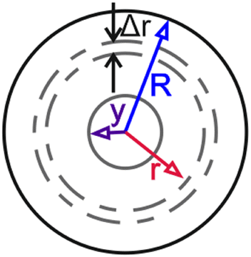 Partially swollen bead of radius R, with an unswollen core of radius y and a shell radius r. Adapted from Goldstein et al.79 Partially swollen bead of radius R, with an unswollen core of radius y and a shell radius r. Adapted from Goldstein et al.79 |
 Interaction between the polymer network (P) and the solvent molecules (S) for the Maxwell–Stefan equation. Adapted from Taylor and Krishna80 Interaction between the polymer network (P) and the solvent molecules (S) for the Maxwell–Stefan equation. Adapted from Taylor and Krishna80 |
 Change from the unswollen state (r position, dotted lines) to the swollen state (r′ position, continuous line). The deformation vector is u; the dots represent the cross-link points. Adapted from Hirotsu76 Change from the unswollen state (r position, dotted lines) to the swollen state (r′ position, continuous line). The deformation vector is u; the dots represent the cross-link points. Adapted from Hirotsu76 |
| M t = KtaSolvent uptake (Mt) as a function of time. K is a proportion constant if a = ½, diffusion is Fickian | F dr,i = Ffr,iThe net driving force on component i equals the friction between i and other components | u = r′ − rDisplacement vector definition |
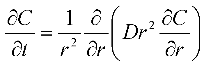 Radial diffusion into a sphere. C is concentration. D is the diffusion coefficient
|
 The driving force Fdr of the swelling process is the sum of the Flory–Huggins chemical potential μFH and the elastic term μel
|
 Equation of motion for the movement of a microscopic volume element of the gel. σik is the stress tensor and ρ is the density of the element
|
| D = D0(1 + αC)Example of linear dependency of the diffusion coefficient with concentration. D0 is the effective diffusivity coefficient through the swollen region, and α is a constant |
 Friction between the solvent and the polymer network. R is the gas constant, T is the temperature, ϕ is the volume fraction of the polymer, and us and up are the velocities of the solvent and the polymer, respectively
|
 Stress tensor definition for an isotropic material. This is the same as the definition given by Newton's law of viscosity. K is the bulk modulus, μ is the shear modulus, and δij is the Kronecker delta
|
| Boundary and initial conditions | ||
| C = 0, t = 0, 0 < r < RThe initial concentration in the bead is zero | D eff = D0f(ϕ)The effective diffusion coefficient Deff is a function of the swelling degree and the diffusion coefficient of the species in the free solution D0 |
 Strain tensor for an isotropic material. In Cartesian coordinates, x1, x2, and x3 equals the coordinates x, y, and z
|
| C = 1, t > 0, r > RConcentration at the surface remains constant | u s(1 − ϕ) + upϕ = 0The linear velocity at which the outside element in the polymer network moves outward equals the swelling velocity (bootstrap relation) |
 Fundamental THB equation
|
| ∂C/∂r = 0, r = 0There is no gradient across the centre of the sphere (symmetry) |
 GMS equation for swelling of hydrogels
|
 Definition of the diffusion coefficient in the THB theory
|
| θ = tD0/r02, x = r/r0Dimensionless variables (r0 is the initial radius) |
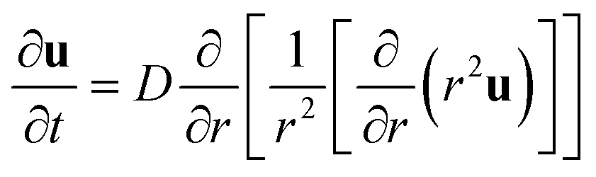 The equation for a spherical symmetrical gel. Here, the vector notation u is dropped as only the radial coordinate is considered
|
|
| Boundary and initial conditions | Boundary and initial conditions | |
| (μFH + μS)r=rp = μLs (at any θ)The chemical potential of the solvent at the outside radius in the gel bead equals the chemical potential in the surrounding liquid | u(r, 0) = Δa0(r/a∞) (t = 0)The network is initially under uniform stress | |
| ϕ(θ = 0) = ϕ0 (at any x)Initial state of the bead | (K + 4μ/3)(∂u/∂r) + 2(K − 2μ/3)(u/r) = 0 (r = a∞)The stress normal to the surface is zero | |
The solid support is dynamic,10,28 with its composition changing during each synthesis cycle. Although SPS typically involves multiple solvents and reagents, few studies address solvent replacement dynamics.81,82 A better understanding of the swelling kinetics could lead to optimized process times during resin washing steps. These washing steps have been investigated to reduce solvent consumption,36 and for peptide synthesis, free-bulk evaporation resulted in wash-free synthesis protocols.83
For mathematical formulation, several models have been proposed to predict swelling kinetics (see Table 1). The Tanaka–Hocker–Benedek (THB) theory84,85 assumes the polymeric network is Hookean and balances the network stresses and friction forces;86,87 Mazich and Rossi have also proposed Fick's second law with a moving boundary condition.88–90 In addition, the generalized Maxwell-Steffan (GMS) approach has been shown to predict the swelling kinetics of hydrogels.86,91 Next, we review some relevant research on swelling kinetics modeling.
For the swelling of 8% DVB cross-linked polystyrene spherical beads (450–500 μm) at 25 °C with dichloromethane (DCM), trichloroethane (TCE), tetrahydrofuran (THF), and benzene79 swelling could be considered a Fickian (case I) process by relating the weight of absorbed solvent per unit area Mt with time as follows:
| Mt = Kta | (1) |
Another model based on Fick's second law with a moving boundary formulation to account for “the fact that polymeric material is displaced as solvent moves”88 was proposed.88–90 Their model accurately predicts the swelling kinetics for cis-1,4-polyisoprene beads mixed with different amounts (1–5 pph) of dicumyl peroxide, with an initial radius of around 6.2 mm, and toluene as solvent at room temperature.
In contrast to the above Fickian approaches and spherical geometries, Hakiki and Herz93 studied the swelling of polystyrene cylinders (8 mm × 50 mm). For THF as solvent at room temperature, the THB model accurately fits the experimental data with diffusion coefficients (for the THB theory) in the order of 1.5 × 10⁻⁶ cm2 s−1, with an equilibrium time of 30 h. Although solid supports in SPS are spherical, cylindrical coordinates can be relevant for packed beds, where the compacted solid support macroscopically acts like a cylinder.33,94
Bisschops et al.86 first proposed the GMS approach to study the swelling kinetics of dextran cross-linked with epichlorohydrin (spheres; 100–300 μm) with water, obtaining a good fit. More recently, the GMS approach was used along with the perturbed-chain statistical associating fluid theory (PC-SAFT) to accurately model the swelling of epoxy resins in water, isopropyl alcohol, and heptane.92,93
Sainio et al.95 used the GMS approach to model the swelling of spherical ion exchange resins. For a PS-DVB functionalized resin (CS08G; 4% cross-linking degree), the GMS approach predicts the shrinking behavior at 25 °C using ethanol–water mixtures as solvents, with initial particle sizes ranging from 521 to 612 μm. The GMS approach also predicts the swelling and shrinking of another PS-DVB functionalized resin (CS16G; 8% cross-linking degree) in water/acetic acid mixtures for initial particle sizes of 900 μm. Interestingly, the GMS approach predicts minimum and maximum values before equilibrium is reached and is compared to Fick's second law: both follow the general trend, but the GMS approach is more accurate as “it takes into account the limited expansion of the polymer network, driven by the chemical potential of the diffusing species”.95 Equilibrium for the two cases above is achieved in around 6 min.
The models and experiments discussed so far are not specific to SPS. The solid supports used in SPS differ significantly in size or shape from some previously described systems. Nevertheless, these studies provide a reference point since studies on swelling kinetics in SPS are scarce. Walsh et al.56 and Vaino and Janda96 reviewed the implications of polymeric supports on SPS, and though the swelling of the resin is a pivotal point in their discussions, they do not mention swelling kinetics.
5. Effect of growing structures on the solid support
Sarin et al.28 investigated, using microscopy, how the molecular size of peptide chains affects the swelling properties of the solid support (polystyrene beads, 1% DVB, 0.22–0.95 mmol g−1 of loading, initial size of 50 μm) by repeating a fixed peptide sequence (Leu–Ala–Gly–Val–oxymethylphenyl acetic acid). After synthesizing the desired molecule size (number of monomers n between 0 and 60), the solid support was dried, and the swelling degree in DCM was measured again; with a loading of 0.95 mmol g−1, the total swollen volume went from about 5 mL g−1 (n = 0) to 12 mL g−1 (n = 60), with the sequence constituting up to 80% w/w of the final solid support (see Fig. 4). | ||
| Fig. 4 Average relative volume (ri/r0)3 for the solid support (1% cross-linking, 0.95 mmol g−1) relation with the number of repeating units (n) from i = 0 to i = n. Dry beads (black squares), compared to swollen particles in DCM (red triangles) and DMF (blue circles); based on the experimental data from Sarin et al.28 (Table III). In all cases, r0 refers to the dry original bead. The insert depicts the relative solvent volume increase [(ri3 − rdi3)/rdi3] comparing the swollen volume to the dry state rd (red dotted line for DCM and blue continuous line for DMF). | ||
The initial swollen volume of the unsubstituted resin was not the final volume of the high-content peptide resin. Even with a high peptide content (80% w/w of the final mass), there was no evidence that a maximum swollen volume was reached as the space available for chain growth increased with the size of the attached molecule (Fig. 4). Notably, glycans of up to 101 units,97 proteins of 164 residues,37 and acrylate polymers of up to 15![[thin space (1/6-em)]](https://www.rsc.org/images/entities/char_2009.gif) 000 g mol−1 (ref. 98) have been obtained using polymeric solid supports.
000 g mol−1 (ref. 98) have been obtained using polymeric solid supports.
The insert in Fig. 4 also shows that the solvation volume can roughly approximate the relative volume change. Two events within the evolution of the swelling behavior are important: a) the change in solvent affinity by adding a few monomers to the chain that may affect the solvation properties, and b) reaching a constant swelling for each solvent once the chain reaches a certain length.
The solvation of the peptide chains within the swollen resin matrix increases the swelling driving force.28 Since the linear peptides are not cross-linked and only one “end” is attached to the solid support, the expansion of the polymeric network does not elongate them, and therefore they are not elastic-hindering the overall solid system. Interestingly, all the experimental points follow a clear trend, indicating that Flory–Huggin's theory may be modified to include the effect of the growing molecule.
In search of a real-time monitoring method for reaction progress in SPPS, a variable bed flow reactor (VBFR; see Fig. 5) was used to measure resin swelling by maintaining a differential pressure of 8 bar in a packed bed consisting of solid support.11 The results agree with earlier measurements, as the resin bed volume presented a net positive variation after the coupling of every new amino acid; for the JR-10 peptide, the net change in the size of the resin (0.2 g, MBHA-RAM, 0.5 mmol g−1) was around +0.6 mL. During the deprotection stage, the resin shrinks, further stressing the relationship between the attached molecule size and the swelling properties of the resin.
 | ||
| Fig. 5 Left: Variable bed flow reactor (VBFR) used10,11 for glycan and peptide synthesis. A pressure sensor measures the pressure drop across the packed bed in the resin (in an Omnifit® column) and adjusts it to the desired value by moving the top plunger with the integrated linear motor; the change in pressure is due to changes in the compaction of the solid support. The pressure controller records both the pressure and position via RS-232 commands. Right: Swellographic monitoring (osmotic engine) proposed by Rodionov.32,99 An external force (weight) is applied to the packed bed by adjusting a fixed mass (1.2 kg) in the top-moving plunger; the movement of the fixed mass (due to swelling or shrinking) is measured with a potentiometric position pickup and is registered in a chart recorder; Baru et al.100 proposed a similar system in which pressure drop is recorded. | ||
This experimental setup proved helpful in “establishing the structural requirements that promote on-resin peptide aggregation”.11 Tracking aggregation led to selecting the proper conditions for synthesizing the JR10 (MBHA-RAM resin), highlighting the importance of resin loading, as decreasing it from 0.59 mmol g−1 to 0.50 mmol g−1 was the critical change for successful syntheses. The relationship between loading, peptide aggregation, and swelling has been investigated previously.43,101–103
Using the same system for AGA, similar results were obtained: an overall increase in the volume of the resin after the coupling stage, with intermediate decreases during the deprotection stage.10 Throughout the synthesis of a pentamannoside (using chloroform as solvent), the overall change in the resin volume (0.1 g, 0.33 mmol g−1, Merrifield resin with a photolabile linker) was around 0.15 mL. The experimental data showed the same proportionality between the size of the attached molecule and the swelling degree.
To explain this change in the swelling properties of the solid support,10,11 researchers referred to the favorable interactions between the solvents and the π electrons of the aromatic moieties in the protecting groups of the oligosaccharides,28 and also highlighted the vital role of solvation in the swelling process (a topic discussed by Fields and Fields104 and Hancock et al.105): as the oligosaccharide elongates, it displaces solvent molecules, diminishing solvent molecules per mannose unit (solvation number) from an initial value of 60 (monosaccharide) to 9 (pentamannoside). This solvation state prevents two phenomena that could lead to shrinking: self-aggregation and on-resin aggregation.102 It remains unclear how the polymeric matrix and the growing molecules are arranged within the core of the solid support during the construction of large structures.
Previous swellographic studies of SPPS32,99 relied on a continuous flow reactor with a moving piston whose movement (produced by resin volume fluctuations) was continuously recorded, this set-up resembles an osmotic engine106 (see Fig. 5). The volume change in coupling and deprotection was reported, and a linear relationship between the size of the attached peptide and the change in resin volume (1% cross-linked polystyrene) led to the following expression:
| ΔV = ΔM/dR + VM(Σ2 + Σ1) | (2) |
More experimental examples on correlating the growing peptide chain and resin swelling104 use the Hildebrand and hydrogen bonding solubility parameters (creating “contour solvation plots”) to predict the solvation of peptide-resin by single solvents. Cilli et al.107 proposed the sum of the electron acceptor (AN) and electron donor (DN) numbers (Gutmann–Becket method) as the prediction variable for the swelling of the solid support. Tam and Lu108 researched the effect of interchain interaction on the solvation of resin-peptide material through dispersed and clustered peptide chains.
There is consensus regarding the proportionality between the size of the solid support and the size of the attached molecule. The size of the solid support could be a control parameter in SPS; for example, the growth of the beads could be adjusted to the progressive-conversion model (PCM) or the shrinking-core model (SCM).109 This is also feasible as in the synthesis of several peptide sequences (less than 12 amino acids sequences), Wang and Foutch110 showed that the coupling constant is not affected by the length of the resin-bound reagent, but seems to be a function of the reacting amino-acid pair: estimative k-values could then be obtained for single pairs of reacting building to be used in the PCM or the SCM. Still, studies remain primarily descriptive and empirical.17
6. Swelling and temperature
A simple way to observe the effect of temperature on the swelling equilibrium of a polymer network is to consider an Arrhenius-type relationship: | (3) |
Favre111 also used the Flory–Huggins theory, computing the interaction parameter using Hansen solubility parameters:
 | (4) |
It is essential to discuss the significance of the solvent interaction parameter and the meaning of either a good or poor solvent. The dimensionless χ parameter expresses the contact energy per solvent molecule76 and characterizes “the difference in interaction energy of a solvent molecule immersed in a pure polymer compared with one in pure solvent”.113 For a polymer network with molar volume vP and a solvent with molar volume vS, if vP ≫ vS, the Flory–Huggins theory leads to:114
 | (5) |
 , normalized Gibbs free energy, is either zero or negative for all polymer volume fractions ϕ only if χ ≤ ½, a fact related to the “miscibility criteria”114 (negative values for
 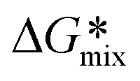 and reaching a minimum for
  ). Accordingly, if χ > 1, the liquid is a non-solvent. If 0.5 < χ < 1, it is an intermediate solvent (plasticizer), and if χ < 0.5 is a good solvent.114,115 The “best” solvents for a polymer will be those with the lowest χ values, indicating a strong polar attraction between the polymer and the solvent and a greater rate for decreasing the free energy of the solution.116 Thermodynamic aspects of swelling have been reviewed previously.76,77
Erman and Baysal57 also used the Flory–Huggins theory to explain the influence of temperature in the swelling of cross-linked polystyrene (∼0.3% DVB; 8 × 3 × 1 mm) using cyclohexane, toluene, and methanol as solvents from 16 to 45 °C. The swelling decreases with increasing temperature for toluene, while the opposite occurs for cyclohexane and a mixture of toluene (75%)–methanol. For the toluene–methanol mixture, a decrease in the temperature reduces the interaction parameter from 0.63 (at 15 °C) to 0.57 (at 45 °C).
Kim et al.117 studied the swelling of one-dimensional polystyrene slabs (thickness between 0.73 and 0.84 mm) with cross-linking (DVB) degrees of 0.5% and 1.0%. For dodecane as a solvent, as temperature increases, so does the swelling degree, and as expected, higher temperatures will result in shorter times to reach the swelling equilibrium. For comparison (1% cross-linking degree), at 120 °C, the equilibrium swelling degree is about 0.18 g g−1 (reached in 20 h), while at 70 °C, the equilibrium swelling degree is 0.05 g g−1 (reached in 80 h).
The use of hands-on parameters as the swelling factor and the resin loading neglected the use of the interaction parameter χ as a decision factor in SPS design, although, as seen, is fundamental in the thermodynamic description of the swelling process. Unfortunately, the experimental studies referenced do not accurately represent the scale and geometry of the particles used in SPS. When the solvent and the temperature range are constant during the synthesis, swelling conditions may be affected only by the increase in the molecule growing on it.10,28
This is probably not true for systems with a continuous replacement of the solvent (as in biopolymer synthesis trough SPS17) and extreme temperature oscillations (as in AGA118).
Moreover, using packed beds36,37,81 and variable bed flow reactors (VBFR)10,11 for SPS creates the additional issue of whether compacting94 the solid support (i.e., increasing the back pressure by applying a force on top of the packed bed) can have an impact on the swelling of the solid support, as it has been shown in the so-called “osmotic engines”106 and in flow distribution studies.33,119
7. Swelling and cross-linking
We distinguished microporous and macroporous supports (section 3), whereby swelling is negligible for the latter due to increased cross-linking. Here, we discuss the effect of cross-linking in microporous supports.Kim et al.117 studied the effect of cross-linking in swelling for polystyrene (slabs with a thickness between 0.73 and 0.84 mm) in aromatic and aliphatic solvents. For polystyrene and dodecane as a solvent, increasing cross-linking from 0.5% to 1.0% will decrease the swelling at equilibrium (at 70 °C) from 0.10 g g−1 to 0.05 g g−1. The required time to reach equilibrium will increase by 30%. The trend was consistent for temperatures between 50–120 °C.
Likewise, Smith and Peppas120 used 3.5–4.6 mm thick polystyrene slabs at 30 °C with cyclohexane as solvent. Even at cross-linking degrees below 1% (DVB), this parameter significantly affects the system: the relative degree of swelling decreases from 3.47 (0.14% cross-linking) to 2.53 (0.44% cross-linking). Peppas and Urdahl121 reported an overshooting effect, where before attaining equilibrium, the polymer network will reach a temporary maximum in the swelling equilibrium; this phenomenon seems to be significant for cross-linking below 1% (DVB) in slabs of polymer (thickness from 0.025 to 0.180 cm) and cyclohexane at 20 °C as solvent. With a cross-linking of 0.53%, the swelling equilibrium value was 56% of the overshoot value (1.80 g g−1).
Errede122 directly correlated the swelling factor (mL g−1) with the cross-linking degree:
| S = C(λ1/3 − λ1/30) | (6) |
Seemingly simple, eqn (6) accurately fits experimental data for several solvents (N,N-dimethylaniline, anisole, pyridine, etc.) and can be derived by assuming that van't Hoff Law for osmotic pressure describes the swelling equilibrium. Errede also proposed using Hildebrand solubility parameters to estimate the relative swelling123 and later showed some limitations of this linear model.124 The expression by Errede shows an inverse relationship between the cross-linking degree and the swelling of the polymeric network. For example, with toluene as a solvent, the swelling factor will diminish from 6.5 mL g−1 (1%) to 1.0 mL g−1 (10%).
Rana et al. studied the influence of cross-linking on the reaction rate for macroporous solid supports.125 For peptide synthesis (Kawaguchipeptin B), increasing the cross-linking degree from 0.3% to 6% reduces the by-products. However, a purity plateau was already reached at 2.1% cross-linking (typical for commercial solid supports). The diffusion rate will decrease with increasing cross-linking degree and can become a limiting factor. Regarding higher purity and yield, Rana et al.125 state that “the greater reactivity and accessibility of sites on the lower cross-linked PS resins” allows “for more side reactions to take place” and/or “increased site-site interactions due to increased site mobility.” However, this reaction purity might be influenced by the loading and the target complexity.
8. On adsorption in SPS
Traditionally, solid phase synthesis has not been described in the context of chemical adsorption.17,24 Strictly speaking, adsorption is specific to solid/liquid interfaces, not swelling polymers.13 However, there are similarities in certain aspects of the processes. The interaction between the building block (as an adsorbed molecule) and the support-bound molecule (active site of the solid support) can be considered chemical adsorption (coupling event in Fig. 1) since “the adsorbed molecules are linked to the surface by valence bonds, they will occupy adsorption sites on the surface, and only one layer of chemisorbed molecules will form (monolayer adsorption)”.126Bautista et al.127,128 exemplify the modeling of the adsorption phenomenon in cross-linked polystyrene by studying the adsorption equilibria of aspartame in modified XAD-2 resins (macroporous styrene-divinylbenzene copolymers) and fitting the experimental data to the Langmuir and Toth models. A model accounting for film, surface, and pore diffusion solved by finite differences was used to obtain the kinetic parameters by minimizing the square error. For temperatures between 0 and 25 °C, for several modified resins (XAD-2-Br, XAD-Et-Br, XAD-Me-Br, and XAD-Me-Cl; 500–800 μm), this model satisfactorily describes the experimental data, when investigating the adsorption in a 100 mL solution with a 0.075 mg mL−1 aspartame concentration, 0.5–1.5 g of resin and mixing rate of 600 rpm. The assessment of the process by a concerted and integral model led to the conclusion that both intraparticle mechanisms for diffusion are significant, that surface diffusion contribution decreases with temperature, and that the interaction strength of the adsorbate with the polymeric network plays a pivotal role.
Similarly, Yu et al.129 used sulfone-modified cross-linked (2–10%) polystyrene beads (0.45–1 mm) for separation via adsorption of several aromatic/aliphatic mixtures at 50 °C. The separation is possible for feed concentrations of aromatics below 15%, with separation factors between 3.3 and 7.42. Cross-linked polystyrene beads have been used to absorb phenolic compounds from aqueous solutions,130,131 and for CO2 adsorption.132 However, these studies are related to ion exchange (macroporous) resins, not SPS.
Should SPS account for both physical and chemical adsorption? Rademann et al.13 found gradients in chemical coupling through the bead radius under sub-stoichiometric amounts of reactants. Still, their experiment does not strictly reproduce the chemistry during the SPS coupling step. A diffusion study revealed the need for an unexpectedly long washing time,13 related to the physical adsorption (attributed to π–π interactions) of the tracking species in the polymeric network. Yamane et al.133 and Gambs et al.45 also discussed the physical interaction (adsoprtion) between aminoacids building blocks and the polystyrene network trough diffusion ordered-spectroscopy (DOSY) experiments, noting the possible reduction in chemical reactivity. This matter reamains an open question.
Conclusions and outlook
We summarized the state of the art regarding swelling and surface phenomena in SPS. Most studies did not address SPS conditions, such as typical solid support size and geometry, temperature range, solvents, and model reactions. Few examples extract physicochemical data directly from SPS experimental data,10,11,28,32,125 limiting the descriptve information available from and for the process.Regarding swelling behavior, the assumption of a temperature-independent process is unreasonable; experimentation under a comprehensive temperature range is needed. For bead size in SPS, the time scale of swelling appears to be in the order of 100 s (characteristic time for a 140 μm DCM-swollen bead computed with the diffusion coefficient reported by Goldstein et al.79); however, kinetics should be determined considering SPS process conditions (temperature, solvent, reactor configuration) and solid support properties (dimensions, surface chemistry, cross-linking degree). The total contribution of these factors remains an open question.
At least three physical models, Fick's second law, THB, and GMS, describe swelling kinetics in equivalent systems. Rodionov32,99,100 swelling studies provide the most straightforward empirical correlation for the relation between swelling and attached molecule size. As the attached molecule grows, the resin bead expands, and the swelling behaviour changes. Fundamental questions remain: what is the maximum size for the hosted molecule? From a more practical perspective, can the variation of the resin size be used to monitor synthesis progress dynamically? In general, efforts to explain the relationship between solid support swelling and the size of the attached molecule remain descriptive.
Applying the terms physical and chemical adsorption to their strict definition might be debatable over slightly cross-linked polymers, but the experimental evidence and physical resemblance encourage implementing the corresponding mathematical models to describe the reagent interactions at the solid/liquid interface.
Physicochemical processes should be analyzed as critical factors contributing to designing and optimizing operational modules and reactors for automated SPS34,35 (Fig. 1). Independent of the target molecule, all technical development should begin by defining the physical parameters of the reaction environment.17
Data availability
No primary research results, software or code have been included and no new data were generated or analysed as part of this review. Fig. 4 used data from Table III in ref. 28.Author contributions
SPL prepared the original draft, MK and ETS edited it, and JDF conceptualized and supervised the work. PHS managed the project and resources, contributing to the writing and editing of the manuscript. JDF and PHS are both corresponding authors. All authors have read and approved the content of the manuscript.Conflicts of interest
There are no conflicts to declare.Acknowledgements
We gratefully acknowledge financial support from the Max-Planck Society. Open Access funding provided by the Max Planck Society.Notes and references
- R. N. Zuckermann, J. M. Kerr, S. B. Kent and W. H. Moos, J. Am. Chem. Soc., 1992, 114, 10646–10647 CrossRef CAS.
- L. A. Thompson and J. A. Ellman, Chem. Rev., 1996, 96, 555–600 CrossRef CAS.
- C. M. Runnels, K. A. Lanier, J. K. Williams, J. C. Bowman, A. S. Petrov, N. V. Hud and L. D. Williams, J. Mol. Evol., 2018, 86, 598–610 CrossRef CAS PubMed.
- R. Merrifield, Science, 1965, 150, 178–185 CrossRef CAS PubMed.
- P. H. Seeberger, Acc. Chem. Res., 2015, 48, 1450–1463 CrossRef CAS.
- G. Lowe and T. Vilaivan, J. Chem. Soc., Perkin Trans. 1, 1997, 555–560 RSC.
- International Union of Pure and Applied Chemistry (IUPAC), gel, 3.0.1 edn, 2019, DOI:10.1351/goldbook.G02600.
- J. K. Magtaan, M. Devocelle and F. Kelleher, J. Pept. Sci., 2020, 26, e3250 CrossRef CAS PubMed.
- J. Danglad-Flores, S. Leichnitz, E. T. Sletten, A. Abragam Joseph, K. Bienert, K. Le Mai Hoang and P. H. Seeberger, J. Am. Chem. Soc., 2021, 143, 8893–8901 CrossRef CAS PubMed.
- E. T. Sletten, J. Danglad-Flores, M. Nuño, D. Guthrie and P. H. Seeberger, Org. Lett., 2020, 22, 4213–4216 CrossRef CAS.
- E. T. Sletten, M. Nuño, D. Guthrie and P. H. Seeberger, Chem. Commun., 2019, 55, 14598–14601 RSC.
- S. R. McAlpine and S. L. Schreiber, Chem. – Eur. J., 1999, 5, 3528–3532 CrossRef CAS.
- J. Rademann, M. Barth, R. Brock, H. J. Egelhaaf and G. Jung, Chem. – Eur. J., 2001, 7, 3884–3889 CrossRef CAS.
- J. Kress, R. Zanaletti, A. Rose, J. G. Frey, W. S. Brocklesby, M. Ladlow and M. Bradley, J. Comb. Chem., 2003, 5, 28–32 Search PubMed.
- B. Furman, R. Łysek, Ł. Matyjasek, W. Wojtkielewicz and M. Chmielewski, Synth. Commun., 2001, 31, 2795–2802 CrossRef CAS.
- K. Le Mai Hoang, A. Pardo-Vargas, Y. Zhu, Y. Yu, M. Loria, M. Delbianco and P. H. Seeberger, J. Am. Chem. Soc., 2019, 141, 9079–9086 CrossRef CAS.
- S. Pinzón-López, M. Kraume, J. Danglad-Flores and P. H. Seeberger, React. Chem. Eng., 2023, 8, 2951–2962 RSC.
- M. H. Caruthers, Science, 1985, 230, 281–285 CrossRef CAS PubMed.
- O. J. Plante, E. R. Palmacci and P. H. Seeberger, Science, 2001, 291, 1523–1527 CrossRef CAS.
- R. K. Singh, J. Sianturi and P. H. Seeberger, Org. Lett., 2022, 24, 2371–2375 CrossRef CAS PubMed.
- K. Sadler and J. P. Tam, Rev. Mol. Biotechnol., 2002, 90, 195–229 CrossRef CAS.
- C. J. Bailey, P. R. Flatt and J. M. Conlon, Peptides, 2023, 161, 170939 CrossRef CAS.
- L. Christensen, R. Fitzpatrick, B. Gildea, K. H. Petersen, H. F. Hansen, T. Koch, M. Egholm, O. Buchardt, P. E. Nielsen and J. Coull, J. Pept. Sci., 1995, 1, 175–183 CrossRef CAS.
- I. Langmuir, J. Am. Chem. Soc., 1918, 40, 1361–1403 CrossRef CAS.
- H.-J. Egelhaaf and J. Rademann, J. Comb. Chem., 2005, 7, 929–941 CrossRef CAS PubMed.
- C.-W. Chang, M.-H. Lin, C.-H. Wu, T.-Y. Chiang and C.-C. Wang, J. Org. Chem., 2020, 85, 15945–15963 CrossRef CAS PubMed.
- B. Merrifield, Br. Polym. J., 1984, 16, 173–178 CrossRef CAS.
- V. K. Sarin, S. B. Kent and R. Merrifield, J. Am. Chem. Soc., 1980, 102, 5463–5470 CrossRef CAS.
- I. Alshanski, M. Bentolila, A. Gitlin-Domagalska, D. Zamir, S. Zorsky, S. Joubran, M. Hurevich and C. Gilon, Org. Process Res. Dev., 2018, 22, 1318–1322 CrossRef CAS.
- Y. Bakhatan, I. Alshanski, C.-K. Chan, W.-C. Lo, P.-W. Lu, P.-H. Liao, C.-C. Wang and M. Hurevich, Chem. – Eur. J., 2022, 29, e202300897 CrossRef.
- P. Strauss, F. Nuti, M. Quagliata, A. M. Papini and M. Hurevich, Org. Biomol. Chem., 2023, 21, 1674–1679 RSC.
- I. L. Rodionov, I. A. Peshenko, L. K. Baidakova and V. T. Ivanov, Int. J. Pept. Res. Ther., 2007, 13, 161–171 CrossRef CAS.
- V. Sans, N. Karbass, M. I. Burguete, E. García-Verdugo and S. V. Luis, RSC Adv., 2012, 2, 8721–8728 RSC.
- K. Ferentzi, D. Nagy-Fazekas, V. Farkas and A. Perczel, React. Chem. Eng., 2024, 9, 58–69 RSC.
- B. Tamás, P. L. Willi, H. Bürgisser and N. Hartrampf, React. Chem. Eng., 2024, 9, 825–832 RSC.
- A. J. Mijalis, D. A. Thomas III, M. D. Simon, A. Adamo, R. Beaumont, K. F. Jensen and B. L. Pentelute, Nat. Chem. Biol., 2017, 13, 464–466 CrossRef CAS.
- N. Hartrampf, A. Saebi, M. Poskus, Z. P. Gates, A. J. Callahan, A. E. Cowfer, S. Hanna, S. Antilla, C. K. Schissel and A. J. Quartararo, Science, 2020, 368, 980–987 CrossRef CAS.
- M. H. Lin, Y. T. Kuo, J. Danglad-Flores, E. T. Sletten and P. H. Seeberger, Chem. – Eur. J., 2024, e202400479 CrossRef CAS.
- Z. P. Gates and N. Hartrampf, Pept. Sci., 2020, 112, e24198 CrossRef CAS.
- M. n. Guberman and P. H. Seeberger, J. Am. Chem. Soc., 2019, 141, 5581–5592 CrossRef CAS.
- R. I. Hogrefe, B. Midthune and A. Lebedev, Isr. J. Chem., 2013, 53, 326–349 Search PubMed.
- D. Maclean, J. Baldwin, V. Ivanov, Y. Kato, A. Shaw, P. Schneider and E. Gordon, Pure Appl. Chem., 1999, 71, 2349–2365 CrossRef CAS.
- A. K. Tickler and J. D. Wade, Curr. Protoc. Protein Sci., 2007, 50, 11–16 Search PubMed.
- A. W. Czarnik, Biotechnol. Bioeng., 1998, 61, 77–79 Search PubMed.
- C. Gambs, T. J. Dickerson, S. Mahajan, L. B. Pasternack and K. D. Janda, J. Org. Chem., 2003, 68, 3673–3678 Search PubMed.
- S. Kiil and K. Dam-Johansen, J. Controlled Release, 2003, 90, 1–21 CrossRef CAS.
- F. Svec and J. M. Frechet, Science, 1996, 273, 205–211 Search PubMed.
- A. H. Muhr and J. M. Blanshard, Polymer, 1982, 23, 1012–1026 CrossRef CAS.
- J. A. Wesselingh, J. Controlled Release, 1993, 24, 47–60 CrossRef CAS.
- K. Jerabek, Anal. Chem., 1985, 57, 1598–1602 CrossRef CAS.
- M. Tsyurupa and V. Davankov, React. Funct. Polym., 2006, 66, 768–779 CrossRef CAS.
- Z. Yu and M. Bradley, Curr. Opin. Chem. Biol., 2002, 6, 347–352 CrossRef CAS PubMed.
- J. W. Labadie, Curr. Opin. Chem. Biol., 1998, 2, 346–352 CrossRef CAS PubMed.
- M. D. Price, J. L. Radosevich, M. J. Kurth and N. E. Schore, React. Funct. Polym., 2003, 55, 131–137 CrossRef CAS.
- B. P. Santora, M. R. Gagné, K. G. Moloy and N. S. Radu, Macromolecules, 2001, 34, 658–661 CrossRef CAS.
- D. Walsh, D. Wu and Y.-T. Chang, Curr. Opin. Chem. Biol., 2003, 7, 353–361 CrossRef CAS.
- B. Erman and B. Baysal, Macromolecules, 1985, 18, 1696–1700 CrossRef CAS.
- C. Amadi-Kamalu, H. Clarke, M. McRobie, J. Mortimer, M. North, Y. Ran, A. Routledge, D. Sibbald, M. Tickias and K. Tse, ChemistryOpen, 2020, 9, 431–441 CrossRef CAS PubMed.
- P. H. Toy, T. S. Reger, P. Garibay, J. C. Garno, J. Malikayil, G.-y. Liu and K. D. Janda, J. Comb. Chem., 2001, 3, 117–124 CrossRef CAS PubMed.
- C. J. Rogers, T. J. Dickerson, P. Wentworth Jr and K. D. Janda, Tetrahedron, 2005, 61, 12140–12144 CrossRef CAS.
- S. M. Alesso, Z. Yu, D. Pears, P. A. Worthington, R. W. Luke and M. Bradley, Tetrahedron, 2003, 59, 7163–7169 CrossRef CAS.
- R. Santini, M. C. Griffith and M. Qi, Tetrahedron Lett., 1998, 39, 8951–8954 CrossRef CAS.
- O. Al Musaimi, B. G. de la Torre and F. Albericio, Green Chem., 2020, 22, 996–1018 RSC.
- J. J. Boruah, S. P. Das, S. R. Ankireddy, S. R. Gogoi and N. S. Islam, Green Chem., 2013, 15, 2944–2959 RSC.
- D. Das, A. Sivaramakrishna, C. Brahmmananda Rao, N. Sivaraman and K. Vijayakrishna, Polym. Int., 2018, 67, 374–379 CrossRef CAS.
- F. Coutinho and R. Cid, Eur. Polym. J., 1990, 26, 1185–1188 CrossRef CAS.
- F. Coutinho and D. Rabelo, Eur. Polym. J., 1992, 28, 1553–1557 CrossRef CAS.
- D. Rabelo and F. Coutinho, Polym. Bull., 1993, 30, 725–728 CrossRef CAS.
- D. Rabelo and F. Coutinho, Eur. Polym. J., 1994, 30, 675–682 CrossRef CAS.
- M. T. Gokmen and F. E. Du Prez, Prog. Polym. Sci., 2012, 37, 365–405 CrossRef CAS.
- I. Zlatev, M. Manoharan, J. J. Vasseur and F. Morvan, Curr. Protoc. Nucleic Acid Chem., 2012, 50, 1–28 Search PubMed.
- B. Bacsa, K. Horvati, S. Bosze, F. Andreae and C. O. Kappe, J. Org. Chem., 2008, 73, 7532–7542 CrossRef CAS PubMed.
- M. L. Huggins, J. Chem. Phys., 1941, 9, 440–440 CrossRef CAS.
- P. J. Flory, J. Chem. Phys., 1942, 10, 51–61 CrossRef CAS.
- P. J. Flory and J. Rehner, J. Chem. Phys., 1943, 11, 512–520 CrossRef CAS.
- T. Hirotsu, in Gels Handbook, Elsevier, 2001, pp. 65–97 Search PubMed.
- J. A. Paulin, J. E. Lopez-Aguilar, B. Fouconnier, R. O. Vargas and F. Lopez-Serrano, Polym. Bull., 2021, 1–24 Search PubMed.
- C.-Y. Hui and V. Muralidharan, J. Chem. Phys., 2005, 123, 1–7 CrossRef PubMed.
- S. Goldstein, E. Segall and G. Schmuckler, J. Macromol. Sci., Chem., 1975, 9, 449–460 Search PubMed.
- R. Taylor and R. Krishna, Multicomponent mass transfer, John Wiley & Sons, 1993 Search PubMed.
- R. Scott, K. K. Chan, P. Kucera and S. Zolty, J. Chromatogr. Sci., 1971, 9, 577–591 CrossRef CAS.
- B. G. De La Torre, S. Ramkisson, F. Albericio and J. Lopez, Org. Process Res. Dev., 2021, 25, 1047–1053 CrossRef.
- J. M. Collins, S. K. Singh, T. A. White, D. J. Cesta, C. L. Simpson, L. J. Tubb and C. L. Houser, Nat. Commun., 2023, 14, 8168 CrossRef CAS PubMed.
- T. Tanaka, L. O. Hocker and G. B. Benedek, J. Chem. Phys., 1973, 59, 5151–5159 CrossRef CAS.
- T. Tanaka and D. J. Fillmore, J. Chem. Phys., 1979, 70, 1214–1218 CrossRef CAS.
- M. Bisschops, K. C. A. Luyben and L. Van Der Wielen, Ind. Eng. Chem. Res., 1998, 37, 3312–3322 CrossRef CAS.
- B. Lanel, D. Barthes-Biesel, C. Regnier and T. Chauve, Biorheology, 1997, 34, 139–153 CAS.
- K. A. Mazich, G. Rossi and C. A. Smith, Macromolecules, 1992, 25, 6929–6933 CrossRef CAS.
- G. Rossi and K. A. Mazich, Phys. Rev. A: At., Mol., Opt. Phys., 1991, 44, R4793 CrossRef CAS PubMed.
- G. Rossi and K. A. Mazich, Phys. Rev. E, 1993, 48, 1182 CrossRef CAS PubMed.
- G. Mathe, A. Albersdörfer, K. Neumaier and E. Sackmann, Langmuir, 1999, 15, 8726–8735 CrossRef CAS.
- J. Crank, The mathematics of diffusion, Oxford University Press, 1979 Search PubMed.
- A. Hakiki and J. E. Herz, J. Chem. Phys., 1994, 101, 9054–9059 CrossRef CAS.
- M. Cárdenas-Barrantes, D. Cantor, J. Barés, M. Renouf and E. Azéma, Soft Matter, 2022, 18, 312–321 RSC.
- T. Sainio, M. Laatikainen and E. Paatero, in Ion Exchange and Solvent Extraction, CRC Press, 2007, pp. 1–44 Search PubMed.
- A. R. Vaino and K. D. Janda, J. Comb. Chem., 2000, 2, 579–596 CrossRef CAS PubMed.
- A. A. Joseph, A. Pardo-Vargas and P. H. Seeberger, J. Am. Chem. Soc., 2020, 142, 8561–8564 CrossRef CAS PubMed.
- G. Szczepaniak, K. Kapil, S. Adida, K. Kim, T.-C. Lin, G. Yilmaz, H. Murata and K. Matyjaszewski, J. Am. Chem. Soc., 2024, 146, 22247–22256 CrossRef CAS PubMed.
- I. L. Rodionov, M. Baru and V. Ivanov, Pept. Res., 1992, 5, 119–125 CAS.
- M. Baru, L. Mustaeva, I. Vagenina, E. Y. Gorbunova and V. Cherskii, J. Pept. Res., 2001, 57, 193–202 CrossRef CAS PubMed.
- C. R. Nakaie, E. Oliveira, E. F. Vicente, G. N. Jubilut, S. E. Souza, R. Marchetto and E. M. Cilli, Bioorg. Chem., 2011, 39, 101–109 CrossRef CAS PubMed.
- V. Krchňák, Z. Flegelová and J. Vagner, Int. J. Pept. Protein Res., 1993, 42, 450–454 CrossRef PubMed.
- B. Yan, Comb. Chem. High Throughput Screening, 1998, 1, 215–229 CAS.
- G. B. Fields and C. G. Fields, J. Am. Chem. Soc., 1991, 113, 4202–4207 CrossRef CAS.
- W. S. Hancock, D. J. Prescott, P. R. Vagelos and G. R. Marshall, J. Org. Chem., 1973, 38, 774–781 CrossRef CAS.
- L. Arens, F. Weißenfeld, C. O. Klein, K. Schlag and M. Wilhelm, Adv. Sci., 2017, 4, 1700112 CrossRef PubMed.
- E. M. Cilli, E. Oliveira, R. Marchetto and C. R. Nakaie, J. Org. Chem., 1996, 61, 8992–9000 CrossRef CAS PubMed.
- J. P. Tam and Y.-A. Lu, J. Am. Chem. Soc., 1995, 117, 12058–12063 CrossRef CAS.
- O. Levenspiel, Chemical reaction engineering, John wiley & Sons, 1998 Search PubMed.
- S. Wang and G. L. Foutch, Chem. Eng. Sci., 1991, 46, 2373–2376 CrossRef CAS.
- E. Favre, Eur. Polym. J., 1996, 32, 1183–1188 CrossRef CAS.
- A. M. Bueche, J. Polym. Sci., 1955, 15, 97–103 CrossRef CAS.
- E. Nagy, in Basic Equations of Mass Transport Through a Membrane Layer, ed. E. Nagy, Elsevier, 2nd edn, 2019, pp. 457–481, DOI:10.1016/B978-0-12-813722-2.00018-2.
- R. D. Sudduth, Pigm. Resin Technol., 2013, 42, 394–405 CrossRef CAS.
- W. H. Ferrell, D. I. Kushner and M. A. Hickner, J. Polym. Sci., Part B: Polym. Phys., 2017, 55, 1365–1372 CrossRef CAS.
- R. Orwell and P. Arnold, Physical Properties of Polymers Handbook, 2006, pp. 233–256 Search PubMed.
- D. Kim, J. M. Caruthers and N. A. Peppas, Macromolecules, 1993, 26, 1841–1847 CrossRef CAS.
- J. Danglad-Flores, E. T. Sletten, E. E. Reuber, K. Bienert, H. Riegler and P. H. Seeberger, Device, 2024, 2, 1–8 CrossRef.
- C. Zhao, C. Pei, J. Sun, Z.-J. Zhao and J. Gong, Chem. Eng. Sci., 2023, 267, 118316 CrossRef CAS.
- M. J. Smith and N. A. Peppas, Polymer, 1985, 26, 569–574 CrossRef CAS.
- N. A. Peppas and K. G. Urdahl, Polym. Bull., 1986, 16, 201–207 CrossRef CAS.
- L. Errede, J. Appl. Polym. Sci., 1986, 31, 1749–1761 CrossRef CAS.
- L. Errede, Macromolecules, 1986, 19, 1522–1525 CrossRef CAS.
- L. Errede and S. Hanson, J. Appl. Polym. Sci., 1994, 54, 619–647 CrossRef CAS.
- S. Rana, P. White and M. Bradley, J. Comb. Chem., 2001, 3, 9–15 CrossRef CAS PubMed.
- D. H. Everett, Pure Appl. Chem., 1972, 31, 577–638 CrossRef.
- L. F. Bautista, J. Pinilla, J. Aracil and M. Martínez, J. Chem. Eng. Data, 2002, 47, 620–627 CrossRef CAS.
- L. F. Bautista, M. M. Plata, J. Aracil and M. Martínez, J. Food Eng., 2003, 59, 319–325 CrossRef.
- H. Yu, Z. Cai, X. Liu, M. Li, Z. Shi and Z. Cui, J. Appl. Polym. Sci., 2014, 131, 1–7 Search PubMed.
- K. Zhang, Q. Wang, Y. Zhou, J. Gao, C. Li and X. Jiang, J. Mol. Liq., 2020, 314, 113641 CrossRef CAS.
- X. Li, Y. Liu, D. Di, G. Wang and Y. Liu, Colloids Surf., A, 2016, 500, 1–9 CrossRef CAS.
- Z. Fu, I. M. A. Mohamed, J. Li and C. Liu, J. Taiwan Inst. Chem. Eng., 2019, 97, 381–388 CrossRef CAS.
- Y. Yamane, M. Matsui, H. Kimura, S. Kuroki and I. Ando, J. Appl. Polym. Sci., 2003, 89, 413–421 CrossRef CAS.
| This journal is © The Royal Society of Chemistry 2025 |