
 Open Access Article
 This Open Access Article is licensed under a Creative Commons Attribution-Non Commercial 3.0 Unported Licence
Gas–liquid flow synthesis of Zn3N2-quantum dots†
Malin G.
Lüdicke
 *,
Jonas
Schramm
,
Martin
Wichert
and
Ralph A.
Sperling
*
*,
Jonas
Schramm
,
Martin
Wichert
and
Ralph A.
Sperling
*
Fraunhofer Institute for Microengineering and Microsystems IMM, Carl-Zeiss-Strasse 18-20, 55129 Mainz, Germany. E-mail: malin.luedicke@posteo.de; ralph.sperling@imm.fraunhofer.de
First published on 11th March 2025
Abstract
Continuous process engineering leads production of fine chemicals to a new level of industrialisation. This study elaborates specifications, benefits and pitfalls for the biphasic, high-temperature synthesis of Zn3N2 quantum dots, which are made from inexpensive and earth-abundant starting materials. A micro-flow tubular reactor equipped with inline/online process sensors and a product analysis device is used. All technical requirements are fulfilled for the corrosive gas and air-sensitive starting and product materials to create a safe pilot plant for reproducible nanoparticle synthesis. The process parameter window yields tunable fluorescent nanocrystals (506–710 nm, 4–10 nm) which broadly match in quality (FWHM: 99–186 nm, QY: 15–56%) with those made in a batch approach. The transfer to a continuous synthesis practice greatly improves throughput because time is reduced as the reaction scheme can be realised in a single process step. In addition, handling effort is minimised with inline reagent dilution and optical spectroscopy which allows product adaptation by tuning of the process parameters in real-time.
Introduction
The transfer from batch to flow reaction synthesis is in the making for nanoparticulate systems like quantum dots (QDs), because of the process-related advantages. These are increased safety, scalability and most importantly, tight control over parameters and product quality. Colloidal QDs consist of a semiconductor core, stabilised by organic surfactants. Their exciton properties are strongly correlated with the nanoparticle size. Therefore, size control leads to tunable emission wavelengths, that light-emitting applications rely on in research and industry.1–5Fig. 1 visualises this tunable spectral coverage of core QDs based on three element classes which were manufactured with advanced reactor designs resulting in major progress. For example, K. Watanabe et al. detailed the emission tunability of CdSe in very small graduations varying six synthesis factors including reactor parameters like the flow rates.6 Two research groups exploited the technical opportunities of flow-chemistry when applying solvothermal conditions which allowed the use of low-boiling fluids.7–9 This approach can bypasses the down-streaming process and separation of the product from commonly high-boiling solvents with respect to the whole production chain. Plus, the results indicate a higher product quality by means of a low particle size distribution. Generally, reaction times could be reduced due to the increased mass and heat transfer in a tube compared to a batch reactor. This led to high margins as demonstrated by A. Nightingale et al. who synthesised 54 g dried CdTe QDs powder. It is worth to note the very low emission oscillation of ±1 nm during the 9 h run.10 Besides that, integration of in situ analysis devices allowed assessment and thus adaptation of process conditions in real-time. Furthermore relevant reaction mechanism details were disclosed based on photoluminescence or diffraction data, like stepwise nucleation mechanisms and corresponding reaction time constants.11–13 Among these selected works, some research groups constructed pilot plants with most modules being computer-controlled.6,14–17 Automation is an adjoining step of the continuous QDs synthesis development because it increases the level of protection for operators, especially if supercritical or hazardous raw materials are used. Furthermore, it simplifies multivariate screening studies6,17 and fine-tuning of product features with the help of instrumentation and controlling techniques.14 The combination with neuronal network algorithms has also been demonstrated to predict condition–property relationships.15,16
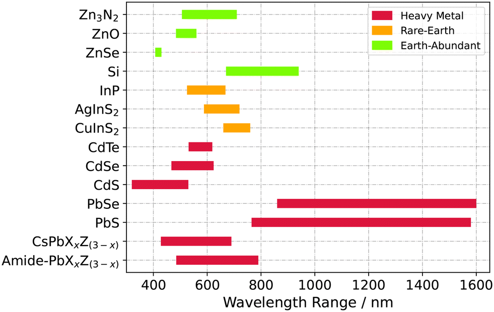 | ||
| Fig. 1 Collection of semiconductor QDs systems produced with flow-chemistry and their adjustable fluorescence emission maxima known from literature. To the best of our knowledge, a continuous synthesis process for Zn3N2 QDs is evaluated for the first time in this study. It is based on non-toxic, earth abundant elements and inexpensive precursors. | ||
From a technical point of view, the transfer from batch to continuous synthesis has not yet been evaluated for Zn3N2 QDs. Therefore, the aim of this study is to demonstrate this transfer and to discuss the challenges and benefits for this material group.
From a material point of view, the raw resources for Zn3N2 are based on non-heavy metal, earth abundant elements and inexpensive precursors. Among semiconductor materials, this is the minority (Fig. 1). Therefore, once finalised for application, this material class offers a more economic and sustainable alternative to In- or Cd/Pb-based ones which lie in a similar wavelength range (ZnO,18,19 ZnSe,20 Si,21,22 InP,23,24 AgInS2,25,26 CuInS2,27,28 PbS and PbSe,29,30 CdS,31,32 CdTe,10,33 CdSe,6 CsPbXxZ(3−x),16,34 amide–PbXxZ(3−x)35,36).
Not many research groups have contributed to the overall comprehension of Zn3N2 QDs so far. To the best of our knowledge, P. Taylor et al. has initially introduced colloidal Zn3N2 (ref. 37) after various works had been published about polycrystalline thin films or nanowires.38–41 Most recently, S. Carter-Searjeant and co-workers achieved the nanoparticulate alloy Li–Zn–N/ZnO starting the synthesis with mere solid and liquid precursors42 while Zn3N2 nanoparticles evolved intermediary as a side-product, i.e. with rather small yield. Besides that, Ahumada-Lazo et al. analysed the optical properties of Zn3N2 in more depth using transient-absorption spectroscopy.43 In brief, their study indicates a rather weak quantum confinement in correlation to increasing particle size (3.8, 5.8, 8.9 nm) based on three data points with biexciton auger lifetimes (3.2–5.0 ps) and absorption cross sections (1.22–2.04 × 10⁻¹⁵ cm2), respectively. In this context, oleylamine was used as the surfactant which donates two electrons for bonding to passivate partial charges at the crystal phase boundary which in turn reduces non-radiative decay. Chemically, the surfactant is a primary amine, a Lewis base or L-type ligand. Empirically, the alkyl chain (C14) of the molecule provides steric hindrance and thus shielding to maintain colloidal stability. Besides oleylamine, literature provides more ligand candidates that show sufficient steric characteristic while they exhibit a stronger base activity for bonding to increase the quantum yield,44,45 that could be applied to the Zn3N2.
With respect to the electronic structure of Zn3N2, its strong oxygen- and water-sensitivity results in the need for carefully performed sample synthesis and investigation. In this context, A. Trapalis et al. presented a systematic structure–property study to juxtapose species involved, N2-deficiency and oxidised phases. According to their results, Zn3N2 can be considered to be a direct semiconductor with a band gap of 1.31–1.38 eV in bulk when stoichiometric while the bandgap is significantly larger after oxidation.40,46 Still, the fast oxidation rate of Zn3N2 results in high precautionary effort during all handling steps: synthesis, spectral analysis and downstream processing.
Here, continuous flow practices can contribute in handling the issue with time-resolved analytical and gas-closed setups. Furthermore, a tube reactor design can be beneficial for the reaction course as the ammonia gas is captured in the reaction medium which in turn increases the contact area between both precursors. Therefore, the central aim of this study is to manufacture Zn3N2 QDs in a microflow reactor, while controlling the optical properties of the product by tuning process parameters. The new synthesis approach is compared to batch results taking into account the inherent product quality and the reaction and measurement necessities. As starting point, the previously reported batch synthesis is reproduced.37 Next, the continuous reactor and synthesis process are realised, introducing diethylzinc (ZnEt2) and NH3 in a biphasic flow with either fixed concentrations or variable dosing of ZnEt2. Furthermore, an online analysis module is integrated directly at the reactor outlet. Offline fluorescence emission analysis is compared alongside, to finally unfold the process parameter room to adjust the properties at different temperatures, concentration levels and average residence times.
Results and discussion
Batch synthesis
The batchwise synthesis protocol37 was reproduced for comparison with the continuous synthesis. The results confirm that Zn3N2 QDs can be generated from ZnEt2 and NH3 as precursors. The fluorescence wavelength maximum logarithmically increases with cyclic ZnEt2 injections at 225 °C (Fig. S1†). In detail, the slope is steep from 503 to 620 nm and flattens at higher emission wavelengths. Besides that, a lower amount of added ZnEt2 precursor (0.25 mmol) results in smaller wavelength gradations with the same slope behaviour. From a kinetic point of view, the reaction solutions immediately changes colour from transparent to honey-yellow after the initial ZnEt2 injection in the right precursor ratio whereas a lasting fluorescence can be detected after ∼2.5 min after the 1st or 3th–4th ZnEt2 injection at 225 or 190 °C, respectively. Within the vessel, however, the fluorescence colour continuously red shifts until the fraction is collected over the course of 5 min. The wavelength slope in this study resembles the results suggested by P. Taylor et al. (NH3 flow of 5 ml min−1).37 Here, a NH3 flow lower than 10 ml min−1, however, causes black precipitation as ZnEt2 decomposes without further conversion into Zn and ethane.47 The same happens with too fast ZnEt2 injections (<20 s) which causes reflux and interruption of the ammonia gas flow. P. Taylor et al. already described the precursor ratio to be crucial for nucleation and growth detailing that higher ZnEt2 starting concentrations did not result in well-defined emission peaks.37190 °C turns out to be the minimal reaction temperature needed (Fig. S1†). Lower reaction temperatures (100, 150 °C) lead to white precipitation, presumably ZnO. Too long pre-heating (0.45 h) of oleylamine in 1-octadecene at 225 °C causes gelification. The wavelength variance per ZnEt2 injection increases with particle size (Fig. S1†). In other words, the slower nanoparticle growth succeeds differently for each batch concluded from the large standard deviations (4–47 nm) between various batches using the same synthesis conditions (Fig. S1†). The reproducibility is even less consistent for 190 °C. Each batch delivers a different nanoparticle growth rate (Fig. S1†).
In conclusion, homogenous heat and precursor distribution are decisive for the generation of Zn3N2 nuclei/clusters to suppress both side products (presumably ZnO and Zn). The nanoparticle growth is not uniform in batchwise synthesis. Specifically, homogeneity within the vessel determines the contact probability of both precursors. At constant magnetic stirrer rate, the gas pressure defines solubility and mixing state in the case of ammonia. The injection speed determines the mixing state in the case of ZnEt2. Both factors mutually interact as ethane gas is released with 6 mol equivalents in the reaction course [3Zn(C2H5)2,liquid + 2NH3,gas → Zn3N2↓ + 6C2H6↑].
Continuous synthesis
Technical and material requirements
A safe continuous synthesis is feasible for Zn3N2 QDs. This accomplishment results from fulfilling technical as well as material requirements. With respect to the experimental setup, both batch and continuous flow synthesis have the NH3 gas-handling components in common (Fig. 2 and S2†), requiring a corrosion-protected pressure regulator (Fig. 2①) followed by a three-way-stop-cock (Fig. 2②) to quickly exchange the back flushing gas (N2) with the reaction gas. The mass flow controller is equipped with Kalrez gaskets also due to the corrosive properties of NH3. Sufficient ammonia flow rate can be supplied by the employed gas cylinder at room temperature as predicted using thermodynamic process simulation (Fig. S3†). In detail, regulation of pressure has the largest influence on the withdrawal amount as gas phase only compared to the influences of water impurities within the gas cylinder or room temperature variations. Experimentally, the pressure sensor detects pressure drops between 1.8 and 2.3 bar during a continuous synthesis session within the pipe system. Electrical heating pads (Fig. 2③) are used as heat sources to prevent re-condensation of ammonia inside the mass flow controller. A check-valve (Fig. 2④) with 0.03 bar opening pressure prevents reflux to the instruments. | ||
| Fig. 2 Photo collage of the experimental setup of the process and P&ID diagram. For Zn3N2 continuous synthesis, the precursors NH3 ①–④ and diethylzinc (ZnEt2) are used. For inline dilution ⑤, the solvent 1-octadecene (ODE) is applied. Controlling units adjust all mass flows. Both precursors are mixed with the help of a static mixer ⑥ before they enter the heat ⑦ and cooling zone ⑧. The synthesis product's emissive properties are then measured within an optical flow cell ⑨ before they are collected at inert gas conditions ⑩. | ||
With respect to the second precursor, ZnEt2, two reservoir bottles are flushed with inert gas (N2). One bottle contains ZnEt2 stock in 1-octadecene and the other neat 1-octadecene for additional inline dilution. Two piston pumps create stable flows as recorded by two individual mass flow controllers. The ZnEt2 component is further diluted using a slit-interdigital micro mixer (Fig. 2⑤) to create flow-dependent input concentrations (Fig. S4†). Both reaction partners join with the help of a T-mixer (Fig. 2⑥) which creates a segmented flow inside a transparent FEP capillary at room temperature (Fig. S5†). At the reactor outlet, gas–liquid segments are not as periodic as at the beginning (Fig. S5†), which can be explained by the gas expansion and changed wetting properties at higher temperatures.
A white solid deposit is gradually formed at the tube wall just before the tube reactor enters the heating zone (Fig. 2⑦). Presumably, this is ZnO that is formed in a side reaction at lower temperature, also observed in the batch synthesis below the onset temperature for Zn3N2 of 190 °C. A more instant temperature transition would minimise this side reaction and the amount of deposited material. As known for ZnO, the residue can be completely dissolved with diluted acetic acid to clean the reactor before priming with 1-octadecene to wet the hydrophobic tube surfaces again before synthesis.
After cooling (Fig. 2⑧) with the help of a waterbath, a fibre-optic assembly (Fig. 2⑨) around the transparent tube reactor allows measuring the fluorescence signals in the running process. In this context, 455 nm or higher excitation wavelengths avoid confusion with oleylamine's autofluorescence, the surfactant in use (Fig. S6†).
To prevent contact with the atmosphere, the fraction collector is sealed in a box (Fig. 2⑩) flushed with N2. The Zn3N2 nanoparticles exhibit a fast decrease of fluorescence in the presence of water and oxygen in atmosphere40 as well as in insufficiently dried solvents (Fig. S7†). The degradation is visible as the wavelength maximum shifts to shorter wavelength (Fig. S7†). Precipitation and re-dispersion do not effect the spectral features when thoroughly dried solvents are used.
The determined average residence times correlate well with the theoretical times based on the reactor volume of 24 ml (Fig. S8†). To ensure static conditions after changing process parameters, 1–2 times the reactor volume was discarded before the synthesis fraction was collected.
Product evaluation
The inherent product quality is equally good comparing batch and continuously manufactured Zn3N2 QDs.Continuously manufactured, a broad spectrum of emission wavelengths can be synthesised ranging from 506 to 710 nm (Fig. 3). Higher emission wavelengths are expected when increasing the input concentrations analogue to batchwise production. Inherently, Zn3N2 offers a high colour brilliance as defined by the International Commission on Illumination, displayed by the CIE colour gamut (Fig. 3). Batchwise and continuously synthesised products show a similar, high colour brilliance, for orange and red emitting QDs in particular.
 | ||
| Fig. 3 Photograph of continuously synthesised Zn3N2 samples at UV-light (left) and their corresponding coordinates in the CIE colour map (right). A broad fluorescence wavelength spectrum can be manufactured in a continuous synthesis manner, namely 506 to 710 nm (left). Zn3N2 QDs inherently offer high colour purity as their emission spectra correspond to CIE coordinates at the edge of the respective colour gamut (right). Here, the dotted triangle spans the standardised Adobe RGB (1998) colour space, thus Zn3N2 QDs exceed this region. | ||
As expected from the quantum confinement effect, the emission wavelength increases with nanoparticle size (Fig. 4 and S9†). In detail, green and orange emitting QDs are small with 4 nm in average albeit they cannot be further differentiated. Red and dark-red QDs have a circular equivalent diameter of 7 and 10 nm in average, emitting at 644 and 684 nm, respectively. The average sizes presented here are comparable to the particle sizes reported previously43 for low emission wavelength peak positions. They are larger in average for red emitting QDs. This discrepancy could be due to the total number of considered objects or due to uncertainty with the interpretation of the particle edges which are demanding considering the microscopic resolution in this small size and atomic number range. With respect to the atomic composition, energy electron loss spectroscopy qualitatively confirms a Zn–N compound (Fig. S10†). It also detects oxygen as an indication of ZnO as a side product. However, ZnO would be expected exclusively if mounting to the microscope at N2 atmosphere had leaked because of the fast decomposition rate (Fig. S7†).
 | ||
| Fig. 4 TEM images at the same magnification level of continuously synthesised Zn3N2 QDs samples. Their spectral properties are summarised in each caption and their size distributions are presented as histograms including their statistical analysis. The average circular equivalent diameter and size dispersity increase from green to red emitting Zn3N2 QDs (4 ± 1 → 10 ± 3 nm). Conversely, the quantum yield was found to be the highest for green and decreases towards red emitting nanocrystals. | ||
With respect to quality criteria, the full widths at half emission maximum (FWHM) are large for batch as well as for continuously fabricated QDs, the latter being equal or up to 9 nm larger at comparable wavelength positions. They FWHM ranges from 99 for green to 186 nm for dark-red emitting nanocrystals (Fig. S11†). This feature can be interpreted as a dispersity indicator of the ensemble since QDs of different sizes contribute to the spectrum. Conversely, this characteristic correlates with the nanoparticle size distribution which also increases towards red emitting QDs according to the microscopic results (Fig. 4). In detail, the microscopic images suggest occasional interparticle growth since some nanoparticles appear to have joined together in a double-sized rod-like shape. A second nucleation of smaller nanoparticles could also result in increased particle size dispersity although oleylamine has demonstrated fast monomer release for nanoparticle nucleation as complexation partner, mostly observed in comparison to its common teammate oleic acid.12,48,49 It should be noted that technical-grade oleylamine was used in this, as in most, studies which contains mainly trans and cis oleylamine but also luminescent C18-amides or nitroalkanes impurities whose impacts on nucleation are not evaluated yet selectively.50 The microscopic images of the Zn3N2 QDs further disclose an increase of windrose shaped nanoparticles with increasing size (Fig. S9†) while the aspect ratio remains similar for all size categories. This indicates atomic addition to selective crystal facets in relation to the monomer amount available comparable with Pt3Fe nanoparticles.51
Another quality characteristic is the fluorescence quantum yield. The results show the highest value for green (56 ± 14%) and the smallest for red emitting QDs (15 ± 6%) (Fig. 4 and S12†). For analysis, rhodamine 6G is used as reference material because its emission properties are more stable in hygroscopic solvents like ethanol or 1,4-dioxane than other candidates, like Nile Red when using low concentrations (<10−5 mol L−1).52–55 In theory, a lowered quantum yield of QDs is the result of exciton trapping states of non-coordinated surface atoms of the nanoparticle. This physicochemical effect is more likely for larger nanoparticles because the nanoparticles surface increases. Using computational bonding studies, this idea was confirmed for previous QDs systems with Z-type ligands as bonding partners.44 In this study, post-synthetic experiments show a higher luminescence of the Zn3N2 QDs when adding additional oleylamine or stronger Lewis bases. Latter solidify the chemical bonding between ligands and surface atoms because ligand solvation competes with surface coordination. In detail, tertiary phosphines show to be more effective to create higher luminescence than amines (Fig. S13†).
Overall, the obtained quantum yield values of Zn3N2 are relatively high compared to other common core QDs considering that no additional shell material is applied yet which can increase the quantum yield and also the absorption cross section. Cu3N could be a suitable shell candidate because crystal growth seems realistic at the phase boundary. The distortion of the coordination octahedra with Cu3N would be max. 0.5 Å, 11°![[thin space (1/6-em)]](https://www.rsc.org/images/entities/char_2009.gif) 56,57 and could be addressed in a future study. Band gap energies of 1.4 and 2.1–3.7 eV were found experimentally for Cu3N bulk materials as well as a work function of around 4.5 eV.58,59 This could result in a type 1 or quasi-type 2 band alignment with Zn3N2 taken the theoretical value of 4.2 eV for the work function of Zn3N2 into account based on bulk material studies.60
56,57 and could be addressed in a future study. Band gap energies of 1.4 and 2.1–3.7 eV were found experimentally for Cu3N bulk materials as well as a work function of around 4.5 eV.58,59 This could result in a type 1 or quasi-type 2 band alignment with Zn3N2 taken the theoretical value of 4.2 eV for the work function of Zn3N2 into account based on bulk material studies.60
Process evaluation
The continuous synthesis process offers savings on time, reagent gas consumption and ultra-dry solvents.The most decisive time saving results from the higher mass transfer compared to the batchwise synthesis because ammonia gas is captured within the reaction medium compared to the rinsing bubbles in a flask. This results in a higher surface area to volume ratio and in turn increases the contact probability with ZnEt2 per volume unit. As a consequence, QDs of a specific size can be produced without the need of stepwise ZnEt2 additions. As an example, QDs grow towards red emission (>620 nm) at 225 °C after 4 individual ZnEt2 injections which equals 20 min during batch synthesis (Fig. S1†). In contrast, the same colour range can be obtained in a single process-step with the same ZnEt2 concentration after 7–10 min in flow synthesis including the time until the same product volume is obtained as in batch synthesis (31 ml). This is an enhancement of circa 50 percent for red emitting quantum dots. Reagent gas is also saved as a consequence of the overall shorter manufacturing time while the ZnEt2 input concentrations are variable and in the same magnitude as for batchwise synthesis. In more detail, a mass flow rate of 3–10 ml min−1 is used for NH3. This equals a molar excess of ∼2–3 in relation to the ZnEt2 mass flow, taking into account NH3's volume expansion at reaction temperature at the given system pressure within the tube reactor which was recorded inline. Smaller molar excesses than 2–3 are conceivable in future works which would allow the use of even less gas supply and a wider residence time range than 2.5–30 min within the same experimental setup.
With respect to the reproducibility, the continuous setup is slightly superior in comparison to batch results concluded from the standard deviations of the emission peak over several flow runs with the same process conditions (Fig. 5 and S1†) comparing the results at similar wavelength positions. They are smaller and the reproducibility is higher in the case of the continuous process. With respect to the impact of the process parameter Average Residence Time, the results are not fully conclusive yet because of the magnitude of standard deviations. This is most probably caused by the aforementioned pressure variations in the system. In future works, it can be further investigated whether the same results can be obtained with even less Average Residence Time to exploit the technical opportunities. The reaction temperature shows the largest impact to tune the wavelength maxima, next to the ZnEt2 concentration. Latter results in a logarithmic increase (Fig. 5). In detail, large wavelength shifts of 27–73 nm and 7–34 nm can be obtained varying temperature and concentration, respectively, while changing the residence time show the lowest impact to tune the wavelength maxima with 2–15 nm for the wavelength shift. As a consequence, the same wavelength can be obtained at 208 °C with 0.15 M ZnEt2 or at 225 °C with only 0.1 M ZnEt2. The reaction mixture or preheated ZnEt2 precursor convert to more Zn or ZnO side products with increasing starting concentration. In future works, more insulation should be provided before heat contact.
 | ||
| Fig. 5 Fluorescence emission maxima of continuously manufactured Zn3N2 QDs as a function of ZnEt2 concentration (left), residence time (right) and reaction temperature (left and right). Standard deviations result from replicate syntheses. Reaction temperature shows the largest impact on the fluorescence emission wavelength position compared to ZnEt2 concentration and residence time. ZnEt2 stock solution was either pre-diluted with the solvent 1-octadecene (Δ) or inline-diluted (∇) during the flow synthesis using the slit-interdigital static mixer (Fig. S4†). In comparison, latter causes smaller wavelength peak positions. | ||
Next to improved mass and heat transfer within the microfluidic reactor, process automation also results in time optimisation. At first, preparation effort is reduced thanks to the inline dilution of ZnEt2's starting concentration. In detail, ZnEt2 stock solution was initially pre-diluted with the solvent 1-octadecene and then inline-diluted during the flow synthesis using the slit interdigital micromixer (Fig. S4†). In comparison, pre-dilutions requires more preparation time at inert gas conditions which results in less flexibility during synthesis. Inline-dilution causes shorter emission wavelengths in a reproducible manner based on the standard deviation of the emission peaks (Fig. 5). This could be due to higher pressure drop registered when using the slit interdigital micromixer compared to the process with pre-dilution. As a consequence, the ammonia gas segments and contact area to ZnEt2 are smaller.
Apart from inline concentration adjustment, the inline analytical setup reliably notifies precursor conversion to the product after the target average residence time. Furthermore, the optical flow measurement delivers emission data which highly agree with the offline emission results (Fig. 6 and S14†). In this context, a baseline drift was observed which is negligible for the peak analysis. Overall, the analytical device results in time-saving because the process parameters can be regulated in real-time. Moreover, the analytical setup reduces measurement effort in order to obtain the product's spectroscopic properties. This includes drying of organic solvents and measurement preparation under inert gas condition. For a more in-depth analysis, the exposure of Zn3N2 to the atmosphere can be minimised to pre-selected samples based on the inline obtained analysis results.
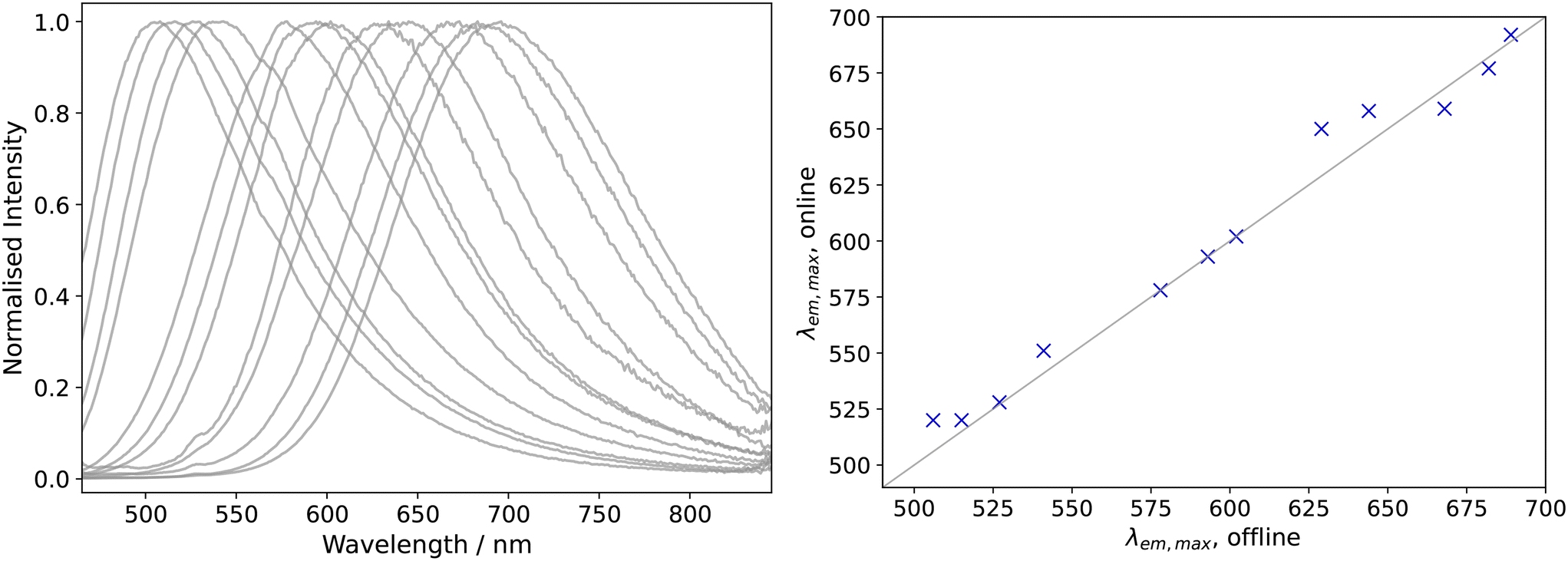 | ||
| Fig. 6 Offline fluorescence emission spectra of selected Zn3N2 samples on the left (same samples as in Fig. 3) which highly correlate with inline measured emission peak positions as shown on the right. Consequently, integration of optical flow cells can reduce preparation time and exposure of the water/oxygen sensitive material alongside the continuous synthesis. | ||
Conclusions and outlook
This work outlines the realisation of the continuous flow synthesis of Zn3N2 quantum dots, providing a safe solution despite its hazardous starting components NH3 and diethylzinc, for the first time. The described procedures provide handling recommendations for future works with Zn3N2 nanoparticles. Overall, the technical investment is beneficial because of time, gas and solvent savings in comparison to the batch-to-batch approach. Moreover, the continuous process offers the advantages of fine-tuning the optical properties and straight-forward synthesis at preparative scale.Future work is directed towards an adequate shell material in a multistage process in order to increase the chemical stability of the core quantum dots. From a technical point of view, additional analytical devices like gas sensors could determine the turnover rate during Zn3N2 production which would allow further optimisation of mass flows, reagent and time savings.
Experimental section
Batch synthesis
For batch synthesis, disclosed procedure steps were adopted from the previously mentioned protocol.37 In detail, 1-oleylamine (OLA, 70%), 1-octadecene (ODE, 90%) and 1.0 M diethylzinc (ZnEt2) in hexanes were purchased from J&KScientific (San Jose, CA, USA) and (Merck KgaA, Germany), respectively. The organic synthesis components were stored at inert gas condition (N2) and used without further purification. A corrosion-resistant pressure regulator was employed for the NH3 gas bottle (99.98%, Linde, Dublin, Ireland) (from 8.5 to 5 bar) while N2 was used as flushing gas. Electrical heating pads guaranteed a temperature level of ca. 50 °C for the gas flow meter (Thermal GAS Mass Flow Meter Controller, EL-FLOW Select F-201CV/Bronkhorst, Gelderland, The Netherlands). The gas component was introduced into the rubber sealed round bottom flask (50 ml) at a rate of 10 ml min−1 using a steel injection needle (0.8 × 120 mm) which was pierced through the septum as well as a thermocouple for temperature control. 30 ml 1-octadecene and 1 ml oleylamine were heated to reaction temperature (190 or 225 °C) at constant stirring rate of 500 U min−1 for 10 min prior to ZnEt2 injection. 1.0 mmol of ZnEt2 was periodically injected into the solution at 5 min intervals which equalled 1 ml of the ZnEt2-hexane stock solution. The fraction collection from the vessel was performed passively via a second needle supported by the positive pressure within the vessel. The whole procedure was performed within a glovebox (MBraun, Garching, Germany) under inert conditions using N2.Continuous synthesis
The same chemicals were used as for the batch synthesis. In contrast, ZnEt2 was introduced in a single process step and was either diluted with ODE beforehand or during flow synthesis (0.05–0.3 mol l−1). The ZnEt2 reservoir was prepared inside the glovebox and stirred for 5 min at 500 U min−1. Sensors informed about the water and oxygen content within the glovebox which did not exceed above 3 ppm. In addition, magnetic stirring bars were heated out at 110 °C over night before use. In this context, the same OLA concentration was applied (3 vol%) as for batch synthesis within the reservoir. Both liquid components (ZnEt2, ODE) reservoirs were flushed with N2 during continuous synthesis while the whole setup was stored in a fume hood at atmospheric conditions. Initially, solely N2 gas and ODE wetted the tube reactor (PTFE, 1/8′′, 12 m, ID = 1.6 mm) until the reaction temperature was reached (190, 208, 225 °C) using an oil bath and a hotplate with internal temperature regulation (Pt1000-thermocouple, Heidolph MR Hei-Tec, Schwabach, Germany). For online analysis, fluorescence signals were recorded using a CCD spectrometer (ULS2048L-RSUSB2 from Avantes, Apeldoorn, Netherlands). For this purpose, a self-built flow cell was applied based on a 5-port union (P-155, IDEX H&S, WA 98277, USA). The tube reactor itself served as the light path (3.2 mm) while fibre optics were aligned (M113L02 Thorlabs, NJ, USA) in a 90° geometry after excitation at 455 nm using a light-emitting diode. Optical emission spectra between 300 and 900 nm were recorded periodically with 1 Hz acquisition rate. ZnEt2 and ODE were delivered simultaneously utilising 10 ml piston pumps (Knauer 40P, Berlin, Germany). The flow rate of each component was electronically captured using mass flow meters (mini Cori-Flow/Bronkhorst, Gelderland, Netherlands), which allowed the adjustment of all concentrations in the resulting flow going into the reactor. In addition, the system pressure drop was determined with a pressure sensor (Little Things Factory, Elsoff, Germany), followed by a check-valve (No.: SS-2C-1/3, Swagelok, Solon, OH, USA). For inline dilution of ZnEt2, homogenous mixing was accomplished using the slit-interdigital micro mixer, developed and manufactured at Fraunhofer IMM (Mainz, Germany).61–63 The segmented gas–liquid flow was realised using a T-mixer (No.: SS-200-3, Swagelok, Solon, OH, USA). Four average residence times were considered (146, 181, 292, 403 s), adjusting all three streams relatively to the total stream flow. To cool the reaction medium, heat exchange was realised at the interface between water and the tube reactor (0.08 m). Serial to the capillary heat exchange, fluorescence properties were thus recorded at room temperature. At the end, a self-built fraction collector comprising a vial holder on top of a stepper motor switched between product and rinsing step, while being flushed with N2 to provide inert conditions. By default, 1–2 times the reactor volume was used for rinsing before product collection. To fully control the flow pilot plant, a LabVIEW program (version 2018) was developed for managing the individual components and to visualize and record the process and optical spectra data.Residence time distribution
The mean residence time distribution was estimated via pulse experiments at 190 °C starting from the 2-phase flow (NH3 and ODE). In detail, Nile Red dye was used as tracer material which was dissolved in ODE and ethanol (4 vol% (ref. 17)), the latter to provide brighter intensity.NH3 mass flow simulation
In order to simulate the withdrawal of anhydrous gaseous ammonia from a steel cylinder, an equivalent process model is developed based on the publication by AirLiquide64 using the ProSim Plus software (version 3.7.4.0, physicochemical properties taken from ProSim Simulis version 2.0.42, Peng–Robinson thermodynamic model). The simulation flowsheet of the process model is illustrated in the ESI† to this publication (Fig. S3†). The steel cylinder (ammonia purity: 99.98%; cylinder volume: 2 L; vendor: Linde Gas AG, Höllriegelskreuth) is represented by a generalised heat exchanger model with an exchange area of A: 0.064 m2 and a clean overall heat transfer coefficient of 5.56 W m−2 K−1 (labelled CYCLINDER in Fig. S3†) and heated by an air flow with a flow rate of 1700 Nm3 h−1 and air temperatures of 20 to 24 °C (stream ATM-1 in Fig. S3†), which were observed under the fume hood used for the experiments. The ammonia feed flow (flow NH3-LIQ in Fig. S3†) is chosen in such a way that a vapor fraction of ≥0.9991 is observed at the outlet of the steel cylinder model (flow NH3-VAP-HP in Fig. S3†) in order to determine the maximum gaseous ammonia threshold quantity for a specified pressure, air flow, air temperature and contamination of the ammonia with water. Ultimately, the ammonia flow is specified as a volume flow in the unit of mL min−1 based on standard conditions (STP: 273.15 K; 101.325 Pa).Purification & ligand testing
Toluene anhydrous and acetonitrile anhydrous (99.8%, Merck KgaA, Germany) were additionally dried, first over 5 vol% regenerated molecular sieve (4 Å) for 1 week. In addition, toluene and acetonitrile were then distilled for ca. 2 h over metallic sodium and CaH2, respectively. Both were stored at inert gas conditions hereafter.For microscopic analysis, Zn3N2 QDs were separated from the oily synthesis components (ODE, OLA) via precipitation and dispersion, twice in the case of orange and red QDs and three times in the case of green QDs. In detail, sample raw material was diluted in ultra-dry toluene by a factor of 4 (df = 4). The solutions blurred adding profoundly dried acetonitrile (40 vol%) which was more evident for larger, red than smaller, green QDs. Relative centrifugal force (2000g, Sigma 1–16k) supported the nanoparticle's sedimentation for 10 min before they were redispersed in fresh toluene to obtain the original dilution factor. The whole purification procedure was performed in a glovebox flushed with N2.
Different surfactants were evaluated after replacing the raw solvent volume with a different surfactant volume. In detail, red QDs were sedimented for 20 min with relative centrifugal force of 20627g and redispersed in ODE and new surfactant (5 mol equivalent in relation to the ZnEt2 concentration: tributylphosphine, trioctylphosphine, 1-octanthiol, 1-dodecanthiol, 1-octanol, 1-undecanol, butylamine). After a 12 h storage at room temperature, the materials were compared with a hand-held UV lamp.
Characterisation
Spectroscopy
Off-line optical spectroscopy was performed with a Cary 50-Scan and a Cary Eclipse for UV/vis and fluorescence spectroscopy, respectively (Agilent Technologies, Santa Clara, CA, USA). This setup provides analysis in a spectral range between 300 and 900 nm. Raw materials were measured within additionally-dried toluene and airtight quartz cuvettes (d = 1 cm, Hellma, Müllheim, Germany) which were dried over night at 110 °C and sealed at inert gas condition for both, blank and sample analysis. As excitation wavelengths, 455 and 480 nm were used. A time gap of 5 min was applied between replicates to evaluate the stability of the emission wavelength position. Offline signals were corrected by wavelength dependent calibration factors according to the manufacturer. CIE coordinates were calculated with the help of a python script.65 Photoluminescence quantum yields were determined relatively to an organic fluorophor.66 As external standard, Rhodamine 6G in isopropanol was used (99.99%, Merck KgaA, Germany) assuming a quantum yield of 95%.67 Confidence intervals (upper and lower) were determined of both linear regression slopes (reference and sample).68 In this context, α = 0.05 was used for the Student's t-distribution. The quantum yield is based on the relation between sample and reference and so is the total error based on the upper sample confidence interval and the lower reference confidence interval.Transmission electron microscopy (TEM) & electron energy loss spectroscopy (EELS)
For visualisation of the Zn3N2 QDs, the purified synthesis solutions were diluted in additionally-dried toluene (df = 100). Then, they were dried on carbon-coated copper grids. The manual transfer to the microscope sample holder succeeded at inert gas condition with the help of liquid and gaseous nitrogen. TEM measurements were performed with a Zeiss Libra 120 electron microscope (Zeiss, Oberkochen, Germany) at 120 kV acceleration voltage for imaging and for spectroscopy. The images were taken by a CCD camera. The circular equivalent diameter [(4 × area/π)1/2] and the size distribution of the nanoparticles were determined by manually retracing the shape within 2 to 4 images. Prior, the grey scaled raw images were processed using a median filter (5 px radius) and contrast factor (0.3%) provided by the software package ImageJ.Data availability
Data supporting this article have been included as part of the ESI.†Author contributions
Malin G. Lüdicke: writing – original draft, writing – review & editing, conceptualization, investigation, methodology, validation, data curation, formal analysis, visualization. Jonas Schramm: writing – review & editing, conceptualization. Martin Wichert: software, formal analysis and Ralph A. Sperling: writing – review & editing, conceptualization, investigation, resources.Conflicts of interest
There are no conflicts to declare.Notes and references
- J. Mondal, R. Lamba, Y. Yukta, R. Yadav, R. Kumar, B. Pani and B. Singh, J. Mater. Chem. C, 2024, 12, 10330–10389 RSC.
- A. A. H. Abdellatif, M. A. Younis, M. Alsharidah, O. Al Rugaie and H. M. Tawfeek, Int. J. Nanomed., 2022, 17, 1951–1970 CrossRef.
- A. Fleming MD, Diabetes Autoimmunity Withdrawn In New Onset and In Established Patients (SUNRISE): NIH Identifier: NCT03895437.
- J.-H. Han and H.-K. Park, Samsung Electronics Co., Ltd. – 2024 1Q Interim Business Report, https://images.samsung.com/is/content/samsung/assets/global/ir/docs/2024_1Q_Interim_Report.pdf.
- M. Hao, Y. Bai, S. Zeiske, L. Ren, J. Liu, Y. Yuan, N. Zarrabi, N. Cheng, M. Ghasemi, P. Chen, M. Lyu, D. He, J.-H. Yun, Y. Du, Y. Wang, S. Ding, A. Armin, P. Meredith, G. Liu, H.-M. Cheng and L. Wang, Nat. Energy, 2020, 5, 79–88 CrossRef.
- K. Watanabe, Y. Orimoto, K. Nagano, K. Yamashita, M. Uehara, H. Nakamura, T. Furuya and H. Maeda, Chem. Eng. Sci., 2012, 75, 292–297 CrossRef.
- S. Marre, J. Park, J. Rempel, J. Guan, M. G. Bawendi and K. F. Jensen, Adv. Mater., 2008, 20, 4830–4834 CrossRef.
- J. Baek, Y. Shen, I. Lignos, M. G. Bawendi and K. F. Jensen, Am. Ethnol., 2018, 57, 10915–10918 Search PubMed.
- C. Ippen, B. Schneider, C. Pries, S. Kröpke, T. Greco and A. Holländer, Nanotechnology, 2015, 26, 085604 CrossRef PubMed.
- A. M. Nightingale, J. H. Bannock, S. H. Krishnadasan, F. T. F. O'Mahony, S. A. Haque, J. Sloan, C. Drury, R. McIntyre and J. C. deMello, J. Mater. Chem. A, 2013, 1, 4067 RSC.
- A. Schiener, A. Magerl, A. Krach, S. Seifert, H.-G. Steinrück, J. Zagorac, D. Zahn and R. Weihrich, Nanoscale, 2015, 7, 11328–11333 RSC.
- M. Abolhasani, C. W. Coley, L. Xie, O. Chen, M. G. Bawendi and K. F. Jensen, Chem. Mater., 2015, 27, 6131–6138 CrossRef.
- M. Herbst, E. Hofmann and S. Förster, Langmuir, 2019, 35, 11702–11709 CrossRef PubMed.
- S. Krishnadasan, R. J. C. Brown, A. J. deMello and J. C. deMello, Lab Chip, 2007, 7, 1434–1441 RSC.
- Y. Orimoto, K. Watanabe, K. Yamashita, M. Uehara, H. Nakamura, T. Furuya and H. Maeda, J. Phys. Chem. C, 2012, 116, 17885–17896 CrossRef CAS.
- K. Abdel-Latif, R. W. Epps, F. Bateni, S. Han, K. G. Reyes and M. Abolhasani, Adv. Intell. Syst., 2021, 3, 2000245 Search PubMed.
- M. G. Lüdicke, J. Hildebrandt, C. Schindler, R. A. Sperling and M. Maskos, Nanomaterials, 2022, 12, 1983 Search PubMed.
- A. Schejn, M. Frégnaux, J.-M. Commenge, L. Balan, L. Falk and R. Schneider, Nanotechnology, 2014, 25, 145606 CrossRef.
- W. Yang, H. Yang, W. Ding, B. Zhang, L. Zhang, L. Wang, M. Yu and Q. Zhang, Ultrason. Sonochem., 2016, 33, 106–117 CrossRef CAS PubMed.
- B.-H. Kwon, K. G. Lee, T. J. Park, H. Kim, T. J. Lee, S. J. Lee and D. Y. Jeon, Small, 2012, 8, 3257–3262 CrossRef CAS.
- R. Gresback, T. Nozaki and K. Okazaki, Nanotechnology, 2011, 22, 305605 Search PubMed.
- T. A. Pringle, K. I. Hunter, A. Brumberg, K. J. Anderson, J. A. Fagan, S. A. Thomas, R. J. Petersen, M. Sefannaser, Y. Han, S. L. Brown, D. S. Kilin, R. D. Schaller, U. R. Kortshagen, P. R. Boudjouk and E. K. Hobbie, ACS Nano, 2020, 14, 3858–3867 Search PubMed.
- J. Baek, P. M. Allen, M. G. Bawendi and K. F. Jensen, Angew. Chem., Int. Ed., 2011, 50, 627–630 CrossRef CAS PubMed.
- P. Cavanaugh, X. Wang, M. J. Bautista, I. J.-L. Plante and D. F. Kelley, J. Chem. Phys., 2023, 159, 134704 CrossRef CAS.
- C. Rivaux, T. Akdas, R. Yadav, O. El-Dahshan, D. Moodelly, W. L. Ling, D. Aldakov and P. Reiss, J. Phys. Chem. C, 2022, 126, 20524–20534 CrossRef CAS.
- H. Ma, L. Pan, J. Wang, L. Zhang and Z. Zhang, Chin. Chem. Lett., 2019, 30, 79–82 CrossRef CAS.
- T. Akdas, M. Haderlein, J. Walter, B. A. Zubiri, E. Spiecker and W. Peukert, RSC Adv., 2017, 7, 10057–10063 RSC.
- A. Yashina, I. Lignos, S. Stavrakis, J. Choo and A. J. deMello, J. Mater. Chem. C, 2016, 4, 6401–6408 RSC.
- J. Pan, A. O. El-Ballouli, L. Rollny, O. Voznyy, V. M. Burlakov, A. Goriely, E. H. Sargent and O. M. Bakr, ACS Nano, 2013, 7, 10158–10166 Search PubMed.
- I. Lignos, L. Protesescu, S. Stavrakis, L. Piveteau, M. J. Speirs, M. A. Loi, M. V. Kovalenko and A. J. deMello, Chem. Mater., 2014, 26, 2975–2982 CrossRef.
- I. Shestopalov, J. D. Tice and R. F. Ismagilov, Lab Chip, 2004, 4, 316–321 RSC.
- H. Yang, W. Luan, Z. Wan, S.-T. Tu, W.-K. Yuan and Z. M. Wang, Cryst. Growth Des., 2009, 9, 4807–4813 Search PubMed.
- S. Yao, Y. Shu, Y.-J. Yang, X. Yu, D.-W. Pang and Z.-L. Zhang, Chem. Commun., 2013, 49, 7114–7116 RSC.
- I. Lignos, S. Stavrakis, G. Nedelcu, L. Protesescu, A. J. deMello and M. V. Kovalenko, Nano Lett., 2016, 16, 1869–1877 CrossRef.
- R. M. Maceiczyk, K. Dümbgen, I. Lignos, L. Protesescu, M. V. Kovalenko and A. J. deMello, Chem. Mater., 2017, 29, 8433–8439 CrossRef.
- X. Liang, R. W. Baker, K. Wu, W. Deng, D. Ferdani, P. S. Kubiak, F. Marken, L. Torrente-Murciano and P. J. Cameron, React. Chem. Eng., 2018, 3, 640–644 RSC.
- P. N. Taylor, M. A. Schreuder, T. M. Smeeton, A. J. D. Grundy, J. A. R. Dimmock, S. E. Hooper, J. Heffernan and M. Kauer, J. Mater. Chem. C, 2014, 2, 4379–4382 RSC.
- M. Zervos, C. Karipi and A. Othonos, Nanoscale Res. Lett., 2013, 8, 221 CrossRef PubMed.
- R. Ayouchi, C. Casteleiro, L. Santos and R. Schwarz, Phys. Status Solidi C, 2010, 7, 2294–2297 CrossRef.
- A. Trapalis, J. Heffernan, I. Farrer, J. Sharman and A. Kean, J. Appl. Phys., 2016, 120, 205102 CrossRef.
- C. G. Núñez, J. L. Pau, M. J. Hernández, M. Cervera, E. Ruíz and J. Piqueras, Thin Solid Films, 2012, 522, 208–211 CrossRef.
- S. Carter-Searjeant, S. M. Fairclough, S. J. Haigh, Y. Zou, R. J. Curry, P. N. Taylor, C. Huang, R. Fleck, P. Machado, A. I. Kirkland and M. A. Green, ACS Appl. Opt. Mater., 2023, 1, 1169–1173 CrossRef PubMed.
- R. Ahumada-Lazo, S. M. Fairclough, S. J. O. Hardman, P. N. Taylor, M. Green, S. J. Haigh, R. Saran, R. J. Curry and D. J. Binks, ACS Appl. Nano Mater., 2019, 2, 7214–7219 CrossRef PubMed.
- C. Giansante and I. Infante, J. Phys. Chem. Lett., 2017, 8, 5209–5215 CrossRef PubMed.
- D. Quarta, M. Imran, A.-L. Capodilupo, U. Petralanda, B. van Beek, F. de Angelis, L. Manna, I. Infante, L. de Trizio and C. Giansante, J. Phys. Chem. Lett., 2019, 10, 3715–3726 CrossRef PubMed.
- A. Trapalis, I. Farrer, K. Kennedy, A. Kean, J. Sharman and J. Heffernan, Appl. Phys. Lett., 2017, 111, 122105 CrossRef.
- A. A. Koski, S. J. W. Price and B. C. Trudell, Can. J. Chem., 1976, 54, 482–487 CrossRef.
- G. Almeida, L. Goldoni, Q. Akkerman, Z. Dang, A. H. Khan, S. Marras, I. Moreels and L. Manna, ACS Nano, 2018, 12, 1704–1711 CrossRef PubMed.
- N. Bao, X. Qiu, Y.-H. A. Wang, Z. Zhou, X. Lu, C. A. Grimes and A. Gupta, Chem. Commun., 2011, 47, 9441–9443 RSC.
- D. Baranov, M. J. Lynch, A. C. Curtis, A. R. Carollo, C. R. Douglass, A. M. Mateo-Tejada and D. M. Jonas, Chem. Mater., 2019, 31, 1223–1230 CrossRef.
- C. Wang, C. Lin, B. Zhao, L. Zhang, A. Kumbhar, G. Fan, K. Sun, J. Zhang, S. Chen and J. Fang, ChemNanoMat, 2015, 1, 331–337 CrossRef.
- D. L. Sackett and J. Wolff, Anal. Biochem., 1987, 167, 228–234 CrossRef PubMed.
- N. Ghoneim, Spectrochim. Acta, Part A, 2000, 56, 1003–1010 CrossRef CAS PubMed.
- C. Würth, M. G. González, R. Niessner, U. Panne, C. Haisch and U. R. Genger, Talanta, 2012, 90, 30–37 CrossRef.
- U. Rocha, L. E. G. Armas, W. F. Silva, M. R. Dousti, A. L. Moura, A. Novatski, N. G. C. Astrath and C. Jacinto, Spectrochim. Acta, Part A, 2024, 317, 124409 CrossRef CAS.
- U. Zachwieja and H. Jacobs, J. Less-Common Met., 1990, 161, 175–184 CrossRef CAS.
- G. Paniconi, Z. Stoeva, R. I. Smith, P. C. Dippo, B. L. Gallagher and D. H. Gregory, J. Solid State Chem., 2008, 181, 158–165 CrossRef CAS.
- A. K. Mukhopadhyay, M. A. Momin, A. Roy, S. C. Das and A. Majumdar, ACS Omega, 2020, 5, 31918–31924 CrossRef CAS PubMed.
- M. I. Rodríguez-Tapiador, J. M. Mánuel, E. Blanco, E. Márquez, N. Gordillo, R. Sainz, J. Merino and S. Fernández, Mater. Sci. Semicond. Process., 2025, 188, 109176 CrossRef.
- S.-H. Yoo, A. Walsh, D. O. Scanlon and A. Soon, RSC Adv., 2014, 4, 3306–3311 RSC.
- P. Löb, K. S. Drese, V. Hessel, S. Hardt, C. Hofmann, H. Löwe, R. Schenk, F. Schönfeld and B. Werner, Chem. Eng. Technol., 2004, 27, 340–345 CrossRef.
- V. Hessel, S. Hardt, H. Löwe and F. Schönfeld, AIChE J., 2003, 49, 566–577 CrossRef CAS.
- P. Löb, in Flow chemistry, ed. S. V. Luis and E. García-Verdugo, Royal Society of Chemistry, Cambridge, 2020, pp. 388–415 Search PubMed.
- B. Franz, H. Hiller, Dr. H. Müller, H. Öhmen and S. Peters, 1x1 der Gase: Physikalische Daten für Wissenschaft und Praxis, Air Liquide Deutshcland GmbH, 3rd edn, 2008 Search PubMed.
- M. Kness, ColorPy v1.1, https://github.com/markkness/ColorPy.
- C. Würth, M. Grabolle, J. Pauli, M. Spieles and U. Resch-Genger, Nat. Protoc., 2013, 8, 1535–1550 CrossRef PubMed.
- D. Magde, R. Wong and P. G. Seybold, Photochem. Photobiol., 2002, 75, 327–334 CrossRef CAS.
- L. Sachs, Applied Statistics: A Handbook of Techniques, Springer New York, New York, NY, 2nd edn, 1984 Search PubMed.
Footnote |
| † Electronic supplementary information (ESI) available. See DOI: https://doi.org/10.1039/d4re00548a |
| This journal is © The Royal Society of Chemistry 2025 |