
 Open Access Article
 This Open Access Article is licensed under a Creative Commons Attribution-Non Commercial 3.0 Unported Licence
Tunable fcc/hcp NiRu alloy nanoparticles anchored on hierarchical N-doped carbon nanosheets for enhanced hydrogen evolution
Zhijuan Li*a,
Minghao Houa,
Xinlong Wanga,
Xiang Songa,
Zishuo Songa,
Shuaiqi Zhua,
Kang Luoa,
Keke Weia,
Yaojuan Hu a and
Tongfei Li*b
a and
Tongfei Li*b
aSchool of Environmental Science, Nanjing Xiaozhuang University, Nanjing 211171, P. R. China. E-mail: lizhijuan@njxzc.edu.cn
bSchool of Chemistry and Chemical Engineering, Nantong University, Nantong 226019, China. E-mail: litongfei@ntu.edu.cn
First published on 26th November 2025
Abstract
Developing highly active, stable and low-cost electrocatalysts for the hydrogen evolution reaction (HER) is crucial for large-scale water electrolysis. Herein, we report a molecule-assisted assembly-pyrolysis strategy to construct hierarchical N-doped carbon nanosheets anchored with NiRu alloy nanoparticles (Ni5Ru@N-C) as a highly active and durable HER electrocatalyst. Strong coordination between iminodiacetonitrile (IDAN) and Ni/Ru ions forms a two-dimensional organometallic coordination polymer (OCP) precursor, which pyrolyzes into thin carbon-layer-encapsulated NiRu nanoparticles with controllable face-centered cubic (fcc) and hexagonal close-packed (hcp) phase, optimizing hydrogen adsorption and catalytic activity. The optimized fcc/hcp Ni5Ru@N-C exhibits an ultralow overpotential of 17 mV at 10 mA cm−2, fast HER kinetics with a Tafel slope of 32 mV dec−1 and excellent durability over 72 h, outperforming that of commercial Pt/C. Moreover, this catalyst demonstrates promising performance in practical two-electrode water electrolyzers. This work provides a molecular-assisted strategy for designing phase- and structure-controlled electrocatalysts for efficient hydrogen production.
1. Introduction
Hydrogen, as a clean, efficient, and renewable secondary energy source, is regarded as a key pathway toward achieving carbon neutrality.1–3 Electrocatalytic water splitting, which produces zero-carbon hydrogen using renewable electricity, has attracted extensive attention in recent years and has become a critical technological route to promote the development of a low-carbon circular economy.4–7 However, the overall efficiency of water electrolysis is limited by the sluggish kinetics of the HER and the oxygen evolution reaction (OER).8,9 Although Pt-based materials are recognized as the most efficient HER catalysts, their scarcity and high cost severely hinder large-scale applications.10–12 Therefore, the development of efficient, stable, and low-cost electrocatalysts to reduce HER overpotential and accelerate reaction kinetics is of great significance for promoting large-scale hydrogen production through electrolysis.Among various candidates, Ni-based catalysts have drawn attention owing to their earth abundance and low cost.13,14 Nevertheless, their relatively strong hydrogen binding energy (HBE) hinders the desorption and release of hydrogen intermediates, thereby restricting HER activity.15,16 By contrast, Ru is considered the most promising HER catalyst after Pt, as it possesses a hydrogen adsorption energy close to that of Pt and can effectively facilitate water dissociation.17–20 However, the scarcity and high cost of Ru also limit its application.21,22 Alloying Ni with Ru offers an effective strategy to simultaneously reduce the usage of noble metals and optimize hydrogen adsorption energy through electronic structure regulation and bimetallic synergistic effects, thereby achieving a balance between performance and cost.23–26 On this basis, crystal phase engineering of metal nanomaterials provides another powerful approach to further enhance catalytic performance modulation can alter the coordination environment and electronic density of states of active atoms, thus directly affecting adsorption energy and reaction pathways.27,28 For instance, Zhang et al. reported that hcp-PtNi exhibits superior HER performance in alkaline media compared with its fcc counterpart.29 In the case of NiRu alloys, hcp facets such as (101) and (100) possess lower HBEs than even Pt (111), which favors the desorption and release of hydrogen intermediates.28,30 Therefore, rationally controlling the synthesis conditions to achieve an optimized combination of fcc and hcp phases represents an effective strategy to construct NiRu catalysts with low Ru content, high activity, and excellent stability.
Meanwhile, catalyst structure and support engineering are also crucial for enhancing performance.31 Hierarchical architectures increase surface area, facilitate mass transport, and enable uniform dispersion and carbon-layer anchoring of alloy nanoparticles, thereby improving active-site utilization and stability.32–34 N-doped carbon supports, with excellent conductivity and strong metal–support interactions (SMSI), can further regulate metal surface electronic states to synergistically enhance activity and durability.35–37 This is particularly vital for metastable hcp phases with poor thermodynamic stability, where protective designs such as “chain-mail” core–shell or nanosheet-encapsulated structures allow electron transfer while shielding against corrosive species.38,39 However, conventional carbon supports loaded by impregnation often yield weak metal–support interactions and poor dispersion.40 By contrast, OCPs provide controllable structures, highly dispersed metal centers, and heteroatom-rich frameworks.41,42 Upon pyrolysis, organic ligands transform into conductive carbon while dispersed metal ions in situ form nanoparticles accompanied by N, S or P doping, thereby simultaneously enhancing catalytic activity and structural stability.43,44
Based on these considerations, we developed an IDAN-assisted assembly-pyrolysis strategy to construct N-doped carbon nanosheet catalysts embedded with NiRu alloy nanoparticles (NiRu@N-C). Strong coordination between IDAN and Ni2+/Ru3+ drives the formation of an ordered 2D coordination polymer precursor, which, after pyrolysis in Ar, yields uniformly dispersed NiRu nanoparticles encapsulated by thin carbon layers. By tuning the Ni/Ru ratio and pyrolysis temperature, the controllable formation of fcc and hcp phases in the alloy can be achieved, enabling performance optimization. Remarkably, the optimized Ni5Ru@N-C containing both fcc and hcp phases, delivers the lowest overpotential, fastest kinetics, and outstanding durability, outperforming Ni@N-C and commercial Pt/C, with promising application in practical two-electrode devices. This work demonstrates an effective approach for phase and structural regulation of NiRu catalysts and provides guidance for the rational design of other multi-metal electrocatalysts.
2. Experimental section
2.1 Materials
Ruthenium(III) acetylacetonate (Ru(acac)3) were purchased from Shanghai Dibai Biotechnology Co., Ltd; nickel(II) acetylacetonate (Ni(acac)2), iminodiacetonitrile (IDAN), benzyl alcohol and potassium hydroxide (KOH) were purchased from Sinopharm Chemical Reagent Co., Ltd (Shanghai, China); commercial Pt/C (20 wt%) and Ru/C (20 wt%) were purchased from Johnson Matthey Chemicals Ltd. All reagents used were of analytical grade and applied as received without additional purification.2.2 Materials preparation
For the synthesis of Ni5Ru@N-C. 60 mg of Ni(acac)2, 18.6 mg of Ru(acac)3, and 150 mg of iminodiacetonitrile were dispersed in 50 mL of benzyl alcohol within a 120 mL Teflon-lined stainless-steel autoclave. The mixture was magnetically stirred for 6 h until fully dissolved and subsequently subjected to solvothermal treatment at 160 °C for 6 h. The resulting solid was isolated by centrifugation, washed several times with ethanol and deionized water, and then dried. Finally, the precursor was annealed at 700 °C for 2 h under an Ar atmosphere with a heating ramp of 3 °C min−1.For comparison, Ni@N-C was obtained by excluding Ru(acac)3 under otherwise identical conditions. Ni3Ru@N-C was synthesized with Ni/Ru = 3![[thin space (1/6-em)]](https://www.rsc.org/images/entities/char_2009.gif) :1 (60 mg Ni(acac)2 and 31 mg Ru(acac)3) and Ni10Ru@N-C was prepared with Ni/Ru = 10:1 (60 mg Ni(acac)2 and 9.3 mg Ru(acac)3) under otherwise identical conditions.
:1 (60 mg Ni(acac)2 and 31 mg Ru(acac)3) and Ni10Ru@N-C was prepared with Ni/Ru = 10:1 (60 mg Ni(acac)2 and 9.3 mg Ru(acac)3) under otherwise identical conditions.
2.3 Physical characterization
Transmission electron microscopy (TEM), high-resolution TEM (HRTEM), high-angle annular dark-field scanning transmission electron microscopy (HAADF-STEM), and energy-dispersive X-ray spectroscopy (EDS) elemental mapping were carried out using a JEOL JEM-2100F microscope operating at an acceleration voltage of 200 kV. X-ray diffraction (XRD) analysis was performed using a Rigaku D/max-rC diffractometer with Cu Kα radiation (λ = 1.5406 Å), at 40 kV and 100 mA. X-ray photoelectron spectra (XPS) analysis was conducted on a Thermo VG Scientific ESCALAB 250 spectrometer using monochromated Al Kα X-rays, with binding energies referenced to the C 1s line at 284.6 eV.2.4. Electrochemical measurements
All electrochemical experiments were carried out at 25 °C using a CHI 760E electrochemical workstation (CH Instruments, Chenhua Co., Ltd, Shanghai) in a standard three-electrode setup. A catalyst-coated glassy carbon disk (3 mm diameter) was used as the working electrode, with a graphite rod and a saturated calomel electrode (SCE) functioning as the counter and reference electrodes, respectively.To prepare the catalyst ink, 2 mg of the catalyst was dispersed via ultrasonication in a 1 mL solvent mixture comprising 0.2 mL ethanol, 0.7 mL deionized water and 0.1 mL Nafion solution. Then, 6 µL of the well-dispersed ink was drop-cast onto the glassy carbon electrode surface and allowed to dry, forming the working electrode.
Hydrogen evolution reaction (HER) testing was performed in nitrogen-saturated 1.0 M KOH electrolytes, using a scan rate of 5 mV s−1. All electrochemical data were corrected for iR drop. The double-layer capacitance (Cdl) was evaluated from a series of cyclic voltammetry (CV) measurements conducted at various scan rates ranging from 20 to 100 mV s−1. The specific value of the electrochemical active area can be calculated using a formula: ECSA = Cdl/Cs, Cs value is 0.040 mF cm−2. Long-term stability assessments were carried out using the chronopotentiometry technique under current densities ranging from 10 to 50 mA cm−2 over a period of 72 hours. Accelerated durability testing (ADT) was performed via continuous CV cycling in the potential window of 0.1 to 0.2 V at a scan rate of 100 mV s−1. All measured potentials were referenced to the RHE scale. RHE calibration was performed based on literature protocols, with the following conversions specific to our electrochemical system: E (RHE) = E (SCE) + 1.068 V in 1.0 M KOH. The overall water splitting was conducted in a two-electrode device, with Ni5Ru@N-C and commercial RuO2 loaded on nickel foams as the cathode and anode, respectively.
3. Results and discussion
As shown in Fig. 1a, a hierarchical sheet-like NiRu@N-C catalyst was successfully constructed via an IDAN molecule-assisted strategy. Specifically, Ni(acac)2 and Ru(acac)3 were employed as metal precursors, while IDAN acted as the organic ligand. Through a mild solvothermal reaction, a two-dimensional layered nanosheet morphology of the IDAN-Ni2+/Ru3+ OCP precursor was obtained. The formation of this two-dimensional sheet-like structure can be primarily attributed to the strong coordination between the nitrile groups in IDAN and the transition metal ions, which induces the generation of a stable planar configuration. Subsequently, the precursor was pyrolyzed at 700 °C under Ar for 2 h, resulting in an in situ transformation into a hierarchical sheet-like framework composed of a nitrogen-doped carbon skeleton, uniformly embedded with NiRu alloy nanoparticles (Ni5Ru@N-C). | ||
| Fig. 1 (a) Schematic demonstration for synthesis of Ni5Ru@N-C; (b) SEM image, (c) TEM image, (d) XRD pattern (e) STEM image and (f) corresponding EDX element mappings of IDAN-Ni2+/Ru3+ OCP. | ||
Morphological characterization (Fig. 1b and c) shows that the IDAN-Ni2+/Ru3+ OCP forms a hierarchical structure composed of numerous interconnected nanosheets. This structure provides a robust foundation and facilitates the formation of a porous carbon framework during subsequent pyrolysis. In addition, it ensures the uniform distribution and full exposure of active sites, thereby laying the groundwork for the excellent electrocatalytic performance of the final product.34 XRD analysis further confirmed the crystalline structure of the precursor (Fig. 1d), where the characteristic diffraction peaks matched well with standard metal cyanide cards, indicating effective coordination between Ni and Ru ions with the nitrile groups of IDAN to form a stable sheet-like coordination polymer. High-resolution STEM and corresponding EDX elemental mapping (Fig. 1h) further confirmed the uniform distribution of Ni, Ru, N, and C within the OCP nanosheets, demonstrating good compositional homogeneity and providing a solid foundation for subsequent catalyst formation. As shown in Fig. 2a, the XRD pattern of the pyrolyzed Ni5Ru@N-C framework exhibits a broad peak at 2θ ≈ 30°, corresponding to the (002) plane of graphitic carbon. The remaining diffraction peaks can be categorized into two groups: peaks at 2θ ≈ 44.2°, 51.4° and 75.8° (* marked) correspond to the (111), (200), and (220) planes of fcc NiRu alloy, showing a negative shift relative to pure Ni (PDF#04-0850); peaks at 38.5°, 42.3° and 44.2° (# marked) are assigned to the (100), (002) and (101) planes of hcp NiRu alloy, exhibiting a positive shift compared to pure Ru (PDF#06-0663). These results indicate that the NiRu@N-C catalyst after pyrolysis contains both fcc and hcp crystalline phases of NiRu alloy nanoparticles. SEM images (Fig. 2b and c) demonstrate that the hierarchical sheet-like structure of Ni5Ru@N-C largely inherits the two-dimensional morphology of the precursor, with a rougher surface likely resulting from IDAN carbonization and in situ formation of NiRu nanoparticles. TEM images further confirm the sheet-like features (Fig. 2d and S1). High-magnification TEM shows that the metal nanoparticles are uniformly distributed on the carbon sheets with an average diameter of ∼18 nm and are coated by thin carbon layers (Fig. S2 and S3). These carbon layers originate from metal-induced carbonization at high temperature, forming a typical core–shell structure that protects the metal core from corrosion and, via metal–carbon electronic interactions, enhances the catalytic activity of the carbon shell, thereby optimizing overall performance.45,46 HRTEM images reveal clear lattice fringes of the metal nanoparticles, where spacings of 0.205 nm and 0.202 nm correspond to the (111) plane of fcc NiRu and the (101) plane of hcp NiRu, respectively, further confirming the coexistence of both crystalline phases (Fig. 2e and f). High-resolution STEM (Fig. 2g) and EDX mapping (Fig. 2h) indicate uniform distributions of C, N, Ni and Ru, further verifying the successful synthesis of nitrogen-doped carbon anchoring the NiRu alloy.
 | ||
| Fig. 2 (a) XRD pattern, (b and c) SEM images; (d) TEM image, (e and f) HRTEM images, (g) STEM image and (h) corresponding EDX element mappings of Ni5Ru@N-C. | ||
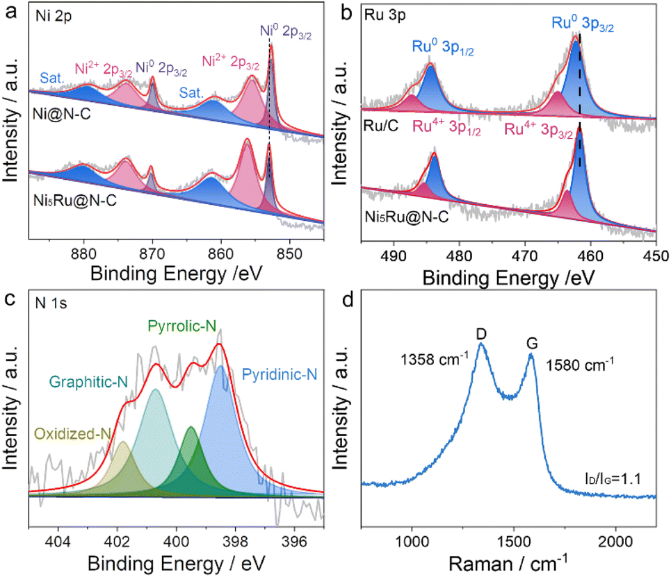
The surface composition and electronic states of Ni5Ru@N-C were investigated by XPS. In the Ni 2p spectrum (Fig. 3a), the peaks at 853.1 and 870.91 eV are assigned to Ni0 2p3/2 and Ni0 2p1/2, while those at 856.0 and 873.8 eV correspond to Ni2+, accompanied by satellite peaks at 861.3 and 880.0 eV, respectively. Compared with Ni@N-C, the Ni0 peaks exhibit an overall positive shift of 0.3 eV, indicating that Ni–Ru alloying significantly modulates the electronic structure, which is beneficial for optimizing the electronic properties of active sites. In the Ru 3d region (Fig. 3b), main peaks appear at 461.7 eV and 483.9 eV, corresponding to metallic Ru, with minor peaks attributable to Ru4+, indicating that Ru mainly exists in the metallic state, favorable for water dissociation and accelerating HER kinetics.39 Compared with that of commercial Ru/C, the Ru 3p peaks in Ni5Ru@N-C are negatively shifted by approximately 0.5 eV, reflecting electronic interaction between Ni and Ru that modulates Ru's electronic structure and further enhances HER activity.2 The N 1s spectrum (Fig. 3c) can be deconvoluted into pyridinic N, pyrrolic N, graphitic N, and oxidized N, with graphitic N and pyridinic N accounting for 30.7% and 38.5%, respectively. The high proportion of active nitrogen species not only introduces abundant defect sites but also enhances conductivity and electronic structure modulation.40 Meanwhile, the C 1s spectrum (Fig. S4) displays three distinct peaks at approximately 284.6 eV, 285.9 eV, and 288.2 eV, corresponding to C–C (sp2-hybridized carbon), C–N, and C![[double bond, length as m-dash]](https://www.rsc.org/images/entities/char_e001.gif) O species, respectively, confirming the successful N-doping of the carbon framework.47 The structural features of the carbon matrix were further analyzed by Raman spectroscopy (Fig. 3d), showing two prominent peaks at 1347 cm−1 and 1594 cm−1, corresponding to disordered/defective carbon (D band) and graphitic sp2 carbon (G band). The intensity ratio (ID/IG) of 1.1 indicates a high degree of defects in the carbon material. Such carbon defects can modify the local electronic density of states, optimize the electronic structure, and increase exposure of surface active sites, providing strong support for the high electrocatalytic performance of NiRu@N-C.48
O species, respectively, confirming the successful N-doping of the carbon framework.47 The structural features of the carbon matrix were further analyzed by Raman spectroscopy (Fig. 3d), showing two prominent peaks at 1347 cm−1 and 1594 cm−1, corresponding to disordered/defective carbon (D band) and graphitic sp2 carbon (G band). The intensity ratio (ID/IG) of 1.1 indicates a high degree of defects in the carbon material. Such carbon defects can modify the local electronic density of states, optimize the electronic structure, and increase exposure of surface active sites, providing strong support for the high electrocatalytic performance of NiRu@N-C.48
 | ||
| Fig. 3 (a) Ni 2p XPS spectra of Ni5Ru@N-C and Ni@N-C; (b) Ru 3p XPS spectra Ni5Ru@N-C and commercial Ru/C; (c) N 1s XPS spectra and (d) Raman spectrum of Ni5Ru@N-C. | ||
To gain deeper insights into the formation mechanism of Ni5Ru@N-C, a series of control experiments were designed and conducted, systematically investigating the effects of metal–ligand coordination, composition ratio, and thermal treatment conditions. First, the coordination effect between metal ions and IDAN was examined. The results indicated that when Ru metal precursors were absent, the resulting IDAN-Ni2+ precursor still maintained a two-dimensional nanosheet morphology (Fig. S5a and b) and, generated uniformly dispersed Ni nanoparticles anchored on nitrogen-doped carbon sheets (Ni@N-C) after pyrolysis (Fig. S5c and d). However, in the absence of Ni precursors or IDAN, no well-defined solid precursor could be obtained. This demonstrates that effective coordination between Ni precursors and IDAN is the key driving force for constructing regular nanosheets. Subsequently, the effect of the Ni/Ru ratio on the structure and phase composition of the products was investigated. TEM results showed that regardless of whether the Ni/Ru ratio was increased (Ni10Ru@N-C) or decreased (Ni3Ru@N-C), the products retained a well-defined two-dimensional nanosheet structure with uniformly distributed metal nanoparticles (Fig. S6). However, XRD analysis revealed that both Ni10Ru@N-C and Ni5Ru@N-C exhibited coexistence of fcc and hcp NiRu alloy phases, whereas Ni3Ru@N-C displayed only fcc NiRu peaks (Fig. 4a). This can be attributed to the influence of Ru content on the NiRu alloy phase: at low Ru content, Ru preferentially enters the Ni lattice, inducing local distortion of the fcc Ni matrix and promoting the formation of the hcp NiRu phase, thereby enabling coexistence of fcc and hcp phases. As the Ru content further increases, the total system energy rises, leading to gradual conversion of unstable hcp NiRu into the more stable fcc phase, eventually retaining only the single fcc NiRu alloy.49,50 These results indicate that the Ni/Ru ratio directly affects the fcc/hcp phase ratio in NiRu alloys and plays a critical role in tuning the crystalline composition. Simultaneously, the influence of pyrolysis temperature on the morphology and phase composition was examined. TEM images revealed that with increasing temperature, the overall two-dimensional nanosheet structure was largely preserved, although local aggregation occurred and the particle size gradually increased (Fig. S7). Corresponding XRD patterns showed that the hcp phase gradually weakened with increasing temperature, and at 800 °C pyrolysis only fcc NiRu peaks were observed (Fig. 4b). This is likely due to thermodynamic factors dominating phase stability: the fcc phase is more stable at higher temperatures, whereas the hcp phase forms at intermediate temperatures due to kinetic advantages but gradually transforms into the fcc phase upon further heating.50 This further highlights the crucial role of pyrolysis temperature in controlling the NiRu alloy phase composition.
 | ||
| Fig. 4 XRD patterns of NiRu@N-C obtained with (a) different Ni/Ru atomic ratios and (b) at different temperatures. | ||
Based on the excellent structure and composition of the catalyst, the HER performance of Ni5Ru@N-C was evaluated in a three-electrode system in 1.0 M KOH, with comparisons to Ni3Ru@N-C, Ni10Ru@N-C, Ni@N-C and commercial Pt/C and Ru/C. As shown in Fig. 5a, all Ru-containing NiRu@N-C samples exhibit significantly enhanced cathodic current densities, even surpassing those of commercial Pt/C and Ru/C, highlighting the crucial role of Ru incorporation in promoting HER activity and further confirming the synergistic effect of Ni–Ru alloying. Among them, the fcc/hcp mixed-phase Ni5Ru@N-C demonstrates the optimal performance, with activity even surpassing that of Ni3Ru@N-C, which contains a higher Ru content but only the to the rational Ni/Ru ratio, which ensures a high proportion of active Ru centers, while the presence of the hcp phase helps optimize the electronic structure and HBE, as well as maintain highly dispersed active sites.44 Previous studies have reported that indicate that the (101) and (100) facets of hcp NiRu possess lower HBEs, even outperforming Pt (111), thereby conferring excellent HER catalytic performance.45 Specifically, Ni5Ru@N-C required overpotentials of only 17 and 35 mV to reach current densities of 10 and 50 mA cm−2, respectively (Fig. 5b), which are far lower than those of Ni@N-C (58 and 138 mV) and Pt/C (27 and 64 mV), and superior to most reported Pt/Ru-based noble metal catalysts (Table S1). In terms of kinetics, Ni5Ru@N-C exhibited a Tafel slope of 30.2 mV dec−1 (Fig. 5c), significantly lower than Ni@N-C (61.3 mV dec−1) and Pt/C (42.7 mV dec−1), consistent with the Volmer–Heyrovsky mechanism, indicating that electrochemical desorption is the rate-determining step and conferring faster reaction kinetics. The electrochemically active surface area (ECSA) was estimated via double-layer capacitance (Cdl) obtained from CV curves (Fig. S8), using the formula ECSA = Cdl/Cs. Ni5Ru@N-C exhibited a Cdl of 12.9 mF cm−2 and an ECSA of 322.5 cm2, significantly higher than Ni@N-C (2.8 mF cm−2, ECSA = 70 cm2) and Pt/C (8.2 mF cm−2, ECSA = 205 cm−2), indicating that the hierarchical sheet-like structure exposes more accessible active sites (Fig. 5d). Electrochemical impedance spectroscopy (EIS) revealed that Ni5Ru@N-C had a much lower charge-transfer resistance compared with Ni@N-C and Pt/C (Fig. 5e), demonstrating enhanced electron transport ability conducive to efficient HER.
 | ||
| Fig. 5 Electrochemical HER performance of catalysts in 1.0 M KOH: (a) LSV polarization curves, (b) overpotential comparison at current densities of 10 and 50 mA cm−2, (c) Tafel slopes, (d) Cdl values (e) Nyquist plots of EIS at open circuit potential, (f) LSV curves recorded before and after ADT, (g) chronopotentiometric long-term stability at current densities ranging from 10 to 50 mA cm−2. (h) Water splitting polarization curves in 1.0 M KOH. (inset) Photograph of H2 and O2 bubbles evolving from Ni5Ru@N-C and RuO2 electrodes. | ||
Regarding stability, after 1000 ADT cycles, the overpotential of Ni5Ru@N-C increased by only ∼2 mV, markedly outperforming Pt/C (13 mV), indicating excellent cycling stability (Fig. 5f). Furthermore, during 72 h chronopotentiometry (CP) tests at current densities of 10–50 mA cm−2, the working potential of Ni5Ru@N-C remained nearly unchanged (Fig. 5g), further confirming its outstanding long-term operational stability. Post-test structural characterization showed that the composition and structure of Ni5Ru@N-C remained intact (Fig. S9), further evidencing its robust structural stability and durability. To evaluate practical applicability, a two-electrode electrolyze was assembled using Ni5Ru@N-C as the cathode and commercial RuO2 as the anode. In 1.0 M KOH, the device achieved a current density of 10 mA cm−2 at 1.52 V (Fig. 5h), significantly outperforming the c-Pt/C∥RuO2 system. These results clearly demonstrate the promising potential of Ni5Ru@N-C for practical water-splitting applications.
4. Conclusion
In this work, we developed an IDAN-assisted strategy to construct hierarchical N-doped carbon nanosheets loaded with NiRu alloy nanoparticles (NiRu@N-C). By tuning the Ni/Ru ratio and pyrolysis conditions, controllable synthesis of fcc and hcp phase NiRu alloys can be achieved, optimizing hydrogen adsorption energy and enhancing catalytic activity. The hierarchical nanosheet structure and carbon-layer anchoring not only increased the specific surface area and utilization of active sites but also stabilized the metastable hcp phase. In alkaline HER, fcc/hcp Ni5Ru@N-C exhibited an ultralow overpotential of 17 mV at 10 mA cm−2, excellent kinetics with a Tafel slope of 32 mV dec−1, and outstanding durability over 72 h of continuous testing. In practical two-electrode devices, using Ni5Ru@N-C as the cathode and commercial RuO2 as the anode, the water electrolyzer required only 1.52 V to achieve 10 mA cm−2, significantly outperforming the Pt/C∥RuO2 system, demonstrating excellent practical applicability. These results indicate that Ni–Ru bimetallic synergy, phase engineering, and support architecture collectively contribute to achieving high activity and stability. This study provides an effective strategy for designing low-Ru NiRu alloy catalysts and offers valuable guidance for phase and structural regulation in bimetallic electrocatalytic systems.Conflicts of interest
There are no conflicts to declare.Data availability
The authors confirm that the data supporting the findings of this study are available within the article and its supplementary information (SI). Supplementary information: characterization data. See DOI: https://doi.org/10.1039/d5ra07051a.Acknowledgements
This work was financially supported by the National Natural Science Foundation of China (22302096, 52502102), the Natural Science Foundation of Jiangsu Higher Education Institutions of China (23KJD150004, 24KJB150026), and Large Instruments Open Foundation of Nantong University (KFJN2526).References
- G. Zhou, Y. Shan, Y. Hu, X. Xu, L. Long, J. Zhang, J. Dai, J. Guo, J. Shen, S. Li, L. Liu and X. Wu, Nat. Commun., 2018, 9, 3366 CrossRef PubMed.
- G. Zhou, S. Zhang, Y. Zhu, J. Li, K. Sun, H. Pang, M. Zhang, Y. Tang and L. Xu, Small, 2023, 19, e2206781 CrossRef PubMed.
- J. Wang and X. Zhang, RSC Adv., 2023, 13, 34057–34063 RSC.
- X. Xu, W. Zhong, L. Zhang, G. Liu and Y. Du, J. Colloid Interface Sci., 2019, 556, 24–32 CrossRef CAS PubMed.
- S. Liu, H. Zhang, X. Mu and C. Chen, Appl. Catal. B Environ., 2019, 241, 424–429 CrossRef CAS.
- G. Zhou, X. Wu, M. Zhao, H. Pang, L. Xu, J. Yang and Y. Tang, ChemSusChem, 2021, 14, 699–708 CrossRef CAS PubMed.
- Q. Chen, J. Huang, D. Chu, L. Cao, X. Li, Y. Zhao, Y. Liu, J. Dong and L. Feng, Exploration, 2025, 5, 20240189 CrossRef PubMed.
- P. Zuo, F. Liu, F. Zhao, X. Zhang, Y. Li, K. Xu, X. Fang, Z. Zhang, Y. Shen, J. Liu and Y. Liu, J. Colloid Interface Sci., 2025, 693, 137560 CrossRef CAS PubMed.
- G. Zhou, C. Wei, Z. Li, B. He, Z. Liu and J. Li, Inorg. Chem. Front., 2024, 11, 164–171 RSC.
- S. Liu, X. Mu, P. Ji, Y. Lv, L. Wang, Q. Zhou, C. Chen and S. Mu, ChemCatChem, 2020, 12, 5149–5155 CrossRef CAS.
- L. Liang, H. jin, H. Zhou, B. Liu, C. Hu, D. Chen, J. Zhu, Z. Wang, H.-W. Li, S. Liu, D. He and S. Mu, J. Energy Chem., 2022, 65, 48–54 CrossRef CAS.
- Y. Tian, C. Qi, R. Zhou, D. Li and T. Han, RSC Adv., 2023, 13, 25246–25252 RSC.
- G. Yanli, Z. Yun, S. Xiaolong and L. Bo, J. Alloys Compd., 2021, 885, 160889 CrossRef.
- T. Li, S. Li, Q. Liu, J. Yin, D. Sun, M. Zhang, L. Xu, Y. Tang and Y. Zhang, Adv. Sci., 2020, 7, 1902371 CrossRef CAS PubMed.
- K.-R. Yeo, H. Kim, K.-S. Lee, S. Kim, J. Lee, H. Park and S.-K. Kim, Appl. Catal. B Environ., 2024, 346, 123738 CrossRef CAS.
- J. Yang, X. Tang, Y. Yuan, J. Zhao, H. Shen and J. Zhao, Fuel, 2026, 404, 136279 CrossRef CAS.
- Y. Liu, S. Liu, Y. Wang, Q. Zhang, L. Gu, S. Zhao, D. Xu, Y. Li, J. Bao and Z. Dai, J. Am. Chem. Soc., 2018, 140, 2731–2734 CrossRef CAS PubMed.
- S. Liu, Q. Liu, Y. Lv, B. Chen, Q. Zhou, L. Wang, Q. Zheng, C. Che and C. Chen, Chem. Commun., 2017, 53, 13153–13156 RSC.
- H.-L. Jia, P.-C. Ji, M.-Y. Guan and S.-H. Zhou, Renewable Energy, 2025, 253, 123594 CrossRef CAS.
- H. L. Jia, J. Zhao, Z. Wang, R. X. Chen and M. Y. Guan, Dalton Trans., 2021, 50, 15585–15592 RSC.
- Y. Saira, Z. Li, Y. Zhu, Q. Liu, W. Luo, Y. Wang, M. Gong, G. Fu and Y. Tang, Chem. Commun., 2024, 60, 2768–2771 RSC.
- L. Feng, H. Yin, L. Dai, Y. Zhang, C. Fu, L. Cao, Y. Li, D. Zhao, Y. Xie and J. Huang, Inorg. Chem. Front., 2023, 10, 6294–6302 RSC.
- S. Ruck, A. Hutzler, S. Thiele and C. van Pham, Small Methods, 2025, 9, e2401179 CrossRef PubMed.
- S. Xu, Z. Li, K. Chu, G. Yao, Y. Xu, P. Niu and F. Zheng, Dalton Trans., 2020, 49, 13647–13654 RSC.
- L. Feng, K. Zhao, L. Dai, D. He, H. Yin, Y. Zhang, J. Chen, L. Cao and J. Huang, Mater. Chem. Front., 2025, 9, 1596–1608 RSC.
- L. Feng, M. Zhou, D. He, H. Yin, Y. Huang, L. Cao, Y. Fang, D. Chu, Y. Liu, H. Chen, G. Li and J. Huang, Chem. Eng. J., 2024, 496, 154255 CrossRef CAS.
- X. Fu, H. Li, A. Xu, F. Xia, L. Zhang, J. Zhang, D. Ma, J. Wu, Q. Yue, X. Yang and Y. Kang, Nano Lett., 2023, 23, 5467–5474 CrossRef CAS PubMed.
- Y. Yuan, L. Zheng, J. Rong, X. Zhao, G. Wu and Z. Zhuang, Chemistry, 2023, 29, e202300062 CrossRef CAS PubMed.
- Z. Cao, Q. Chen, J. Zhang, H. Li, Y. Jiang, S. Shen, G. Fu, B. A. Lu, Z. Xie and L. Zheng, Nat. Commun., 2017, 8, 15131 CrossRef PubMed.
- X. Zhou, G. Wei, C. Liu, Q. Zhao, H. Gao, W. Wang, X. Zhao, X. Zhao and H. Chen, J. Colloid Interface Sci., 2024, 670, 709–718 CrossRef CAS PubMed.
- D. Chen, R. Lu, Z. Pu, J. Zhu, H.-W. Li, F. Liu, S. Hu, X. Luo, J. Wu, Y. Zhao and S. Mu, Appl. Catal. B Environ., 2020, 268, 118729 CrossRef CAS.
- H. Wu, Q. Lu, J. Zhang, J. Wang, X. Han, N. Zhao, W. Hu, J. Li, Y. Chen and Y. Deng, Nano–Micro Lett., 2020, 12, 162 CrossRef CAS PubMed.
- C. Ma, B. Zhu, Y. Wang, S. Ma, J. Shi, X. Zhang and Y. Song, J. Colloid Interface Sci., 2025, 685, 793–803 CrossRef CAS PubMed.
- Y. Teng, L. Zhou, Y. Z. Chen, J. Z. Gan, Y. Xi and H. L. Jia, Dalton Trans., 2023, 52, 15839–15847 RSC.
- D. Chen, J. Zhu, X. Mu, R. Cheng, W. Li, S. Liu, Z. Pu, C. Lin and S. Mu, Appl. Catal. B Environ., 2020, 268, 118729 CrossRef CAS.
- H. Jin, H. Zhou, D. He, Z. Wang, Q. Wu, Q. Liang, S. Liu and S. Mu, Appl. Catal. B Environ., 2019, 250, 143–149 CrossRef CAS.
- P.-C. Ji, Y. Teng, H.-C. Li, M.-Y. Guan and H.-L. Jia, Sustain. Energy Fuels, 2024, 8, 82–89 RSC.
- N. Jin, X. Yang, Y. Li, W. Lai, H. Jiang, Y. Li, K. Liu, Y. Cai, L. Zhang and L. Han, ACS Appl. Energy Mater., 2025, 8, 5299–5308 CrossRef CAS.
- J. M. Yoo, H. Shin, D. Y. Chung and Y. E. Sung, Acc. Chem. Res., 2022, 55, 1278–1289 CrossRef CAS PubMed.
- Y. Si, M. G. Park, Z. P. Cano, Z. Xiong and Z. Chen, Carbon, 2017, 117, 12–19 CrossRef CAS.
- J. Hu, Z. Li, D. Zhao, Z. Han, X. Wu, J. Zhai, Z. Liu, Y. Tang and G. Fu, Green Chem., 2023, 7309–7317 RSC.
- Z. Li, H. Li, M. Li, J. Hu, Y. Liu, D. Sun, G. Fu and Y. Tang, Energy Storage Mater., 2021, 42, 118–128 CrossRef.
- Z. Li, X. Wu, X. Jiang, B. Shen, Z. Teng, D. Sun, G. Fu and Y. Tang, Adv. Powder Mater., 2022, 1, 100020 CrossRef.
- D. Wang, X. Jiang, Z. Lin, X. Zeng, Y. Zhu, Y. Wang, M. Gong, Y. Tang and G. Fu, Small, 2022, 18, e2204063 CrossRef PubMed.
- M. Zhang, J. Guan, Y. Tu, S. Chen, Y. Wang, S. Wang, L. Yu, C. Ma, D. Deng and X. Bao, Energy Environ. Sci., 2020, 13, 119–126 RSC.
- L. Yu, D. Deng and X. Bao, Angew Chem. Int. Ed. Engl., 2020, 59, 15294–15297 CrossRef CAS PubMed.
- Y. Liu, H. Wen, D. Zhou, X. Huang, X. Wu, J. Jiang, X. Guo and B. Li, Appl. Catal. B Environ., 2021, 291, 120094 CrossRef CAS.
- P. Wei, X. Sun, Q. Liang, X. Li, Z. He, X. Hu, J. Zhang, M. Wang, Q. Li, H. Yang, J. Han and Y. Huang, ACS Appl. Mater. Interfaces, 2020, 12, 31503–31513 CrossRef CAS PubMed.
- L. Hou, H. Jang, X. Gu, X. Cui, J. Tang, J. Cho and X. Liu, EcoEnergy, 2023, 1, 16–44 CrossRef.
- D. Kutyła, K. Kołczyk-Siedlecka, A. Kwiecińska, K. Skibińska, R. Kowalik and P. Żabiński, J. Solid State Electrochem., 2019, 23, 3089–3097 CrossRef.
| This journal is © The Royal Society of Chemistry 2025 |