
 Open Access Article
 This Open Access Article is licensed under a Creative Commons Attribution-Non Commercial 3.0 Unported Licence
Enhancing the electrochemical performance of lithium-rich manganese-based layered oxides through the phosphorus–vanadium coating of single-crystalline particles
Baijun Songa,
Fei Ma *b,
Wei Dingb and
Jingkui Quc
*b,
Wei Dingb and
Jingkui Quc
aCollege of Environmental and Chemical Engineering, Dalian University, Dalian, 116622, Liaoning, China
bSchool of Chemistry and Materials Engineering, Liupanshui Normal University, Liupanshui, 553004, Guizhou, China. E-mail: mafei@lpssy.edu.cn
cInstitute of Process Engineering, Chinese Academy of Sciences, Beijing 100190, PR China
First published on 22nd April 2025
Abstract
Lithium-rich manganese-based cathode materials are considered next-generation cathode materials for high-energy-density lithium-ion batteries. However, their practical application is limited by continuous voltage decay, poor cycle stability, and inferior rate performance. In this study, single-crystalline Li1.2Ni0.13Co0.13Mn0.54O2 (LNCMO) with different coating levels of Li3V2(PO4)3 was synthesized using the sol–gel method, moreover, a spinel phase and oxygen vacancies were induced between the bulk material and coating layer during the coating process. This modification strategy can effectively suppress voltage decay, improve the rate performance, and reduce side reactions between the active materials and electrolytes during cycling. These results showed that the Li+ ion diffusion coefficient of the LNCMO electrode modified with 3 wt% phosphorus–vanadium is 52 times that of the original sample. The 3 wt% phosphorus–vanadium modified LNCMO delivers a capacity of 201.4 mA h g−1 at 1C rate and retains 176.4 mA h g−1 (87.7% retention) after 100 cycles at 1C, while the pristine material only displayed 72.2% retention under identical conditions. Furthermore, the average discharge midpoint voltage decay of pristine LNCMO (2.4 mV per cycle) decreased to 1.9 mV per cycle. These results provide insights into the future application of lithium-rich manganese-based materials.
1 Introduction
With the rapid development of electric vehicles and portable electronic devices, there is an increasing demand for high-performance lithium-ion batteries with high energy density, high safety, and low cost.1,2 Currently, the cathode material is a decisive factor, lithium-rich layered cathode materials with the formula xLi2MnO3·(1 − x)LiMO2 (0 < x < 1, M = Ni, Mn, or Co) have emerged as promising candidates for next-generation cathode materials because of several advantages.3–5 However, the unique initial activation mechanism of these materials presents several inherent challenges, including a low initial coulombic efficiency, poor rate capability, continuous structural degradation, and voltage decrease during cycling.6–8To address these challenges, various strategies have been investigated, including surface coating,9 elemental doping,10 and morphological control.11 Coating technology involves covering the surface of the cathode material with electronic, ionic conductors, or non-electrochemically active materials to improve the electrochemical performance or prevent side reactions between the active materials and electrolytes. By designing a special morphology or structure, such as a three-dimensional conductive network12 or microcubes,13 Li1.2Ni0.13Co0.13Mn0.54O2 (LNCMO) with excellent performance and a stable structure can be fabricated. However, the effects of these strategies are typically limited to the outer surfaces of polycrystalline materials, which diminishes the benefits of surface modification.
Single-crystalline structures, characterized by a continuous crystal lattice and a lack of grain boundaries, exhibit superior mechanical strength and structural stability. Single-crystal LNCMO with a suitable particle size can readily undergo surface modification to enhance its electrochemical performance and compaction density.14 However, because of the difficulty in preparing single-crystal particles, their dispersion and uniformity must be improved.
This study aims to further enhance the cycling and rate performance of lithium-rich materials by surface modification of their single-crystal structure. The sol–gel method allows for more precise control of grain size. The LNCMO with a well-distributed submicron-sized single-crystal morphology was prepared using the sol–gel method assisted by ball milling before secondary calcination. Moreover, using NH4VO3 and NH4H2PO4 as raw materials, a one-step method is used to simultaneously achieve fast ion conductor (Li3V2(PO4)3) coating of single crystal particles and surface structure reconstruction induced by NH4+ thermal decomposition. All the above strategies can effectively improve the structural stability and electrochemical performance of the material.
2 Experiment
2.1. Synthesis of LNCMO
First, MnC4H6O4·4H2O, NiC4H6O4·4H2O, and CoC4H6O4·4H2O were dissolved in a certain amount of deionized water and absolute ethanol to obtain solution A, with the stoichiometric ratio of Mn![[thin space (1/6-em)]](https://www.rsc.org/images/entities/char_2009.gif) :Co:Ni = 54:13:13. Then, a mixture of lithium carbonate (lithium source excess 5%) and citric acid was dissolved in dilute nitric acid to obtain solution B; the molar ratio of citric acid relative to all the transition metal ions was 1.35. Solution B was then added dropwise to solution A with stirring, and the pH of the solution was adjusted to 8.0 using ammonia. The solution was then evaporated with continuous stirring at 80 °C until a purple gel formed. The gel was dehydrated at 150 °C in a drying box. Finally, the powder was sintered at 450 °C for 5 h with a heating rate of 2 °C min−1 under an oxygen atmosphere. The powder was crushed by ball milling, and subsequently calcined at 900 °C for 10 h in a tube furnace under an oxygen atmosphere; the heating rate was 3 °C min−1. The LNCMO powder was obtained after cooling to room temperature and fine grinding. A schematic of the preparation of LNCMO is shown in Fig. 1.
:Co:Ni = 54:13:13. Then, a mixture of lithium carbonate (lithium source excess 5%) and citric acid was dissolved in dilute nitric acid to obtain solution B; the molar ratio of citric acid relative to all the transition metal ions was 1.35. Solution B was then added dropwise to solution A with stirring, and the pH of the solution was adjusted to 8.0 using ammonia. The solution was then evaporated with continuous stirring at 80 °C until a purple gel formed. The gel was dehydrated at 150 °C in a drying box. Finally, the powder was sintered at 450 °C for 5 h with a heating rate of 2 °C min−1 under an oxygen atmosphere. The powder was crushed by ball milling, and subsequently calcined at 900 °C for 10 h in a tube furnace under an oxygen atmosphere; the heating rate was 3 °C min−1. The LNCMO powder was obtained after cooling to room temperature and fine grinding. A schematic of the preparation of LNCMO is shown in Fig. 1.
 | ||
| Fig. 1 Schematic of the synthesis of the LNCMO cathode materials. | ||
2.2. Synthesis of surface modified LNCMO
The LNCMO precursor was mixed thoroughly with NH4VO3 (0.5, 1.5 and 2.5 wt% relative to LNCMO) and NH4H2PO4 (0.5, 1.5, and 2.5 wt% relative to LNCMO) in anhydrous ethanol. Subsequently, the mixture was ball milled under air atmosphere at a speed of 800 rpm for 240 min to obtain a fine homogeneous slurry. The resulting slurry was dried at 80 °C for 4 h to obtain powder. The powder was calcined under oxygen atmosphere in a tube furnace at 900 °C for 10 h with a controlled heating rate of 3 °C min−1. After natural cooling to room temperature, the surface-modified LNCMO was obtained and named PV-1wt%, PV-3wt%, and PV-5wt%, respectively.2.3. Material characterization
A Shimadzu XRD-6000 instrument was used for X-ray diffraction (XRD, Japan) analysis at a speed of 2° min−1 in the 2θ range of 10–80°, using a Cu Kα radiation source (λ = 1.5418 Å) at 40 kV and 30 mA. Fourier transform infrared spectroscopy (FTIR, INVENIO S, Germany) was used to verify the presence of specific vibrational modes of LNCMO in the range of 500–4000 cm−1. The morphologies and particle sizes of the samples were studied using field-emission scanning electron microscopy (FESEM) on a Quattro S instrument operating at 5 kV. A detailed analysis of the PV-3wt% samples was carried out using transmission electron microscopy (TEM) at 200 kV on a JEM-F200 device. X-ray photoelectron spectroscopy (XPS, Thermo Escalab 250Xi) was performed to test the chemical valence state and content of the materials and electrodes.2.4. Electrochemical measurements
The active materials, acetylene black, and polyvinylidene fluoride were uniformly mixed in a slurry at a mass ratio of 8:1:1. The slurry was coated onto aluminum foil, dried, and cut into cathodes. A Li tablet was used as the anode material. The electrodes were assembled into CR2032 coin cells, and charge–discharge tests were conducted within a voltage range of 2.0–4.8 V using a CT2001A Land instrument. The cells were tested at various current rates (1C = 250 mA h g−1) within the same voltage window (2.0–4.8 V versus Li/Li+ reference electrode) using a Land Test System (LAND CT2001A) at room temperature. Cyclic voltammetry (CV) and electrochemical impedance spectroscopy (EIS) were performed on an electrochemical workstation (Princeton Applied Research, VersaSTAT 3). CV tests were conducted between 2.0 and 4.8 V at a scanning rate of 0.1 mV s−1. The amplitude voltage of the EIS was 5 mV, and the frequency range was 10−2–105 Hz.
3 Results and discussion
3.1. Morphological and structural analysis
Fig. 2 shows the XRD patterns of LNCMO, PV-1wt%, PV-3wt%, and PV-5wt%. The main peaks of all samples correspond to the LiTMO2 phase with a hexagonal layered structure and R![[3 with combining macron]](https://www.rsc.org/images/entities/char_0033_0304.gif) m space group (α-NaFeO2), corresponding to the standard PDF card PDF #87-1564. The sharp and distinct diffraction peaks observed in all materials correspond to the main crystalline phase, indicating the high crystallinity of the major component and demonstrating that a small amount of coating does not alter the material's structure. The weak peaks between 20° and 25° correspond to monoclinic Li2MnO3.15 In addition, the obvious splitting of the (006)/(012) and (018)/(110) planes of all the samples indicates that both the original samples and the phosphorus–vanadium coated samples exhibit layered structures. Generally, the I(003)/I(104) ratio is used to evaluate the degree of cation mixing. The higher the value, the lower the degree of mixing and the better the order of the layered structure.16,17 Table 1 lists the lattice parameters a, c, c/a, and I(003)/I(104) of the samples. The I(003)/I(104) ratios of LNCMO, PV-1wt%, PV-3wt%, and PV-5wt% were 1.153, 1.171, 1.435, and 1.403, respectively, implying that these surface modifications improved the layered structure of pristine LNCMO. The c/a ratio, which usually represents the layered property of materials, is greater than 4.96, further indicating that the samples have excellent layered structures. Moreover, the lattice constants of all modified samples were very close to that of the pristine sample, indicating that surface modification does not affect the crystal structure of LNCMO.
m space group (α-NaFeO2), corresponding to the standard PDF card PDF #87-1564. The sharp and distinct diffraction peaks observed in all materials correspond to the main crystalline phase, indicating the high crystallinity of the major component and demonstrating that a small amount of coating does not alter the material's structure. The weak peaks between 20° and 25° correspond to monoclinic Li2MnO3.15 In addition, the obvious splitting of the (006)/(012) and (018)/(110) planes of all the samples indicates that both the original samples and the phosphorus–vanadium coated samples exhibit layered structures. Generally, the I(003)/I(104) ratio is used to evaluate the degree of cation mixing. The higher the value, the lower the degree of mixing and the better the order of the layered structure.16,17 Table 1 lists the lattice parameters a, c, c/a, and I(003)/I(104) of the samples. The I(003)/I(104) ratios of LNCMO, PV-1wt%, PV-3wt%, and PV-5wt% were 1.153, 1.171, 1.435, and 1.403, respectively, implying that these surface modifications improved the layered structure of pristine LNCMO. The c/a ratio, which usually represents the layered property of materials, is greater than 4.96, further indicating that the samples have excellent layered structures. Moreover, the lattice constants of all modified samples were very close to that of the pristine sample, indicating that surface modification does not affect the crystal structure of LNCMO.
 | ||
| Fig. 2 XRD patterns of LNCMO, PV-1wt%, PV-3wt%, and PV-5wt%. | ||
| Samples | a (nm) | c (nm) | c/a | I(003)/I(104) |
|---|---|---|---|---|
| LNCMO | 0.28525 | 1.42364 | 4.9909 | 1.153 |
| PV-1wt% | 0.28504 | 1.42174 | 4.9879 | 1.171 |
| PV-3wt% | 0.28512 | 1.42355 | 4.9928 | 1.435 |
| PV-5wt% | 0.28533 | 1.41597 | 4.9626 | 1.403 |
In addition, there was no significant shift in the (003) peak of the modified samples compared to that of LNCMO, which indicates that P and V were not coated into the internal lattice of the material. A few additional peaks can be observed for the PV-3wt% and PV-5wt% samples; the weak peaks at 22.8° and 28.1° can be attributed to the Li3VO4 phase (PDF #13-0249),18 while the peak at 24.3° is the characteristic peak of the Li3V2(PO4)3 phase (PDF #01-072-7074).19 From the above analysis, it can be inferred that P and V were successfully coated onto the primary particles in the form of compounds, mainly Li3V2(PO4)3, when the amount of added raw materials is less than 1.5 wt% (PV-3wt%).
FTIR spectroscopy was used to further investigate the structure of the coating layer. Fig. 3 shows the FTIR spectra of LNCMO and its modified counterparts, with absorption peaks between 400–1300 cm−1 attributed to chemical bond vibrations. The two strong bands at 627 and 546 cm−1 were assigned to the Mn–O bond vibrations and (Co,Ni)O6 elongation peaks of LNCMO,20,21 respectively. The peaks at 1029 and 807 cm−1 correspond to PO43− and VO43−, respectively.22 This indirectly proves that the coating layer exists in the form of Li3V2(PO4)3, Li3VO4, and Li3PO4. However, the peak of VO43− was not clearly observed in PV-1wt% and PV-3wt%; this is consistent with the XRD results that P and V mainly existing in the form of Li3V2(PO4)3 when the amount of added raw materials is less than 1.5 wt% (PV-3wt%).
 | ||
| Fig. 3 FTIR spectra of LNCMO, PV-1wt%, PV-3wt%, and PV-5wt%. | ||
The FESEM images in Fig. 4 show the morphologies of the materials. All the samples exhibited a uniformly sized single-crystal particles in the submicron range. However, single-crystal particles tended to agglomerate when the coating amount increased to a certain amount (PV-5wt%, Fig. 4d), which indirectly indicates that a small amount of coating does not affect the single-crystal morphology of the material (Fig. 4b and c). According to previous studies, the smaller the average particle size, the larger the surface area of the material and the larger the electrolyte contact area.23 Therefore, more metal ions participate in the electrochemical reaction, effectively reducing the polarization of the electrode and promoting the rapid transfer of lithium ions.24 Vibrational density is a measure of the stacking efficiency of a material and directly affects its volumetric energy density.25 Materials with high vibrational densities typically have tighter particle packing and more stable structures.26 The tap density of all the samples was above 2.3 g cm−3, which is higher than that of polycrystalline secondary spherical particles (2.0 g cm−3).27
 | ||
| Fig. 4 SEM images of (a) LNCMO, (b) PV-1wt%, (c) PV-3wt%, and (d) PV-5wt%. | ||
As shown in the XRD and FESEM results, the coating amount of PV-3wt% was a critical value that did not affect the original morphology of LNCMO and did not generate other crystal phases (except Li3V2(PO4)3). The EDS diagram in Fig. 5 shows that PV-3wt% has a uniform distribution of Ni, Co, Mn, P, and V, which further proves the effectiveness of this single-crystal preparation method and coating strategy. High-resolution TEM (HRTEM) was employed to further investigate the morphology and crystal structure of the PV-3wt% sample. The HRTEM image shown in Fig. 6a further demonstrates the uniformity and dispersion of single-crystal particles with sizes of approximately 200–500 nm, which is consistent with the SEM image. Submicron particles can reduce the diffusion distance of lithium ions within the material, thereby improving the electrochemical performance. As shown in Fig. 6b, the PV-3wt% sample exhibited obvious lattice stripes, indicating that it formed a layered structure. The (003) plane is also confirmed in the fast Fourier transform (FFT) image.28,29 The clear and ordered electron diffraction spots on the (003) surface further prove that the material has an ideal layered structure. The lattice fringes of PV-3wt% display an interplanar spacing of 0.471 nm, which is consistent with the (003) plane of the α-NaFeO2 Rm structure or the (001) plane of the C/2m structure.30
 | ||
| Fig. 5 Elemental mapping of PV-3wt% using scanning transmission electron microscopy. | ||
 | ||
| Fig. 6 (a) HRTEM image of PV-3wt% on 200 nm, (b) HRTEM images of different regions marked as V, S, W on 5 nm, and (c) corresponding Fast Fourier Transform (FFT). | ||
In addition, a non-uniform surface (approximately 10 nm thick) was detected on the PV-3wt% sample, consisting of three distinct layers, as shown in Fig. 6b. The outermost region W, with a thickness of 1–2 nm can be attributed to the Li3V2(PO4)3 coating layer. The Li3V2(PO4)3 coating is an ultrathin, highly ion-conducting layer that provides a fast channel for lithium ion diffusion. It also insulates the material from side reactions with the electrolyte.31 The sub-outer region S (varying in thickness from 3 to 4 nm) displayed another type of phase structure, corresponding to the (311) plane of the spinel structure, with an interplanar spacing of 0.253 nm.32 This may be attributed to the decomposition of ammonium ions in the raw material during surface coating, which induces changes in the surface structure of LNCMO, forming stable spinel structures and oxygen vacancies (region V, with a thickness of 2–3 nm). The spinel phase can form a good transition structure at the interface between the two phases and provide fast Li+ migration channels. Oxygen vacancies create a conducive environment for ionic diffusion throughout the material and greatly reduce the emission of gases from the surface.33
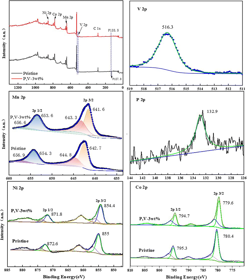
Fig. 7 shows the Ni 2p, Co 2p, Mn 2p, P 2p, and V 2p XPS profiles of LNCMO and PV-3wt%. In the Ni 2p spectrum, the peaks at 871.8 and 854.4 eV represent Ni 2p1/2 and Ni 2p3/2, respectively. Fitting indicated that the Ni2+ content in the PV-3wt% sample (75.1%) was higher than that in LNCMO (68.7%). It has been reported that a high Ni2+ content contributes to structural stability.34 During lithiation, the high Ni3+ content on the surface of the cathode material easily causes a decomposition reaction when a certain amount of Ni4+ is produced, which catalyzes the decomposition of the electrolyte.35,36 In the Mn 2p spectrum, peaks at 641.6 and 653.6 eV correspond to Mn 2p3/2 and Mn 2p1/2, respectively. Peak splitting indicated that the Mn4+ content of the PV-3wt% sample (41.5%) was higher than that of LNCMO (34.5%). The valence state of Mn significantly influences the electrochemical performance and structural stability of the material. Mn3+ exhibits the Jahn–Teller effect, which tends to cause irreversible structural transformations in the material, leading to rapid voltage decay and electrochemical performance degradation.37 Because Mn4+ can act as a pillar to stabilize the structure, the higher Mn4+ content of PV-3wt% represents a more stable structure. The high contents of Mn4+ and Ni2+ further confirm the structural transformation on the surface of LNCMO during the coating process, as revealed by the HRTEM results (Fig. 6). The P 2p peak observed at 132.9 eV signifies the existence of phosphate groups,38 while the V 2p3/2 binding energy located at 516.3 eV is close to that of V3+ for Li3V2(PO4)3.39 These results further indicate that P and V exist on the surface of LNCMO, mainly in the form of Li3V2(PO4)3.
 | ||
| Fig. 7 XPS images of LNCMO and PV-3wt%. | ||
3.2. Electrochemical characterization
Fig. 8a shows the initial charge and discharge curves of LNCMO, PV-1wt%, PV-3wt%, and PV-5wt% at a current density of 0.1C and a voltage range of 2.0–4.8 V. All samples show similar charge and discharge curves; the presence of a slope and a large plateau area is similar to other lithium-rich manganese-based materials.20 The initial charging curve can be divided into two parts: below 4.5 V and above 4.5 V. The voltage charging phase below 4.5 V reflects the migration of lithium ions from the LiMO2 lattice, accompanied by the redox reactions of Ni2+/4+ and Co3+/4+. The platform above 4.5 V represents the release of lithium ions from Li2MnO3. The resulting capacity is attributed to the activation of Mn4+, the desorption of Li+, and the material structure transformation accompanied by the release of oxygen.40–42 The total charge/discharge capacities of LNCMO, PV-1wt%, PV-3wt%, and PV-5wt% are 358.4/256.4, 370.4/284.2, 376.3/292.2, and 299.7/231.6 mA h g−1, respectively, with initial coulombic efficiencies of 71.5%, 76.7%, 77.7%, and 77.3%. Therefore, coulombic efficiency was significantly improved by surface modification, which not only proves the effectiveness of the surface coating strategy but also confirms the results observed by HRTEM that the surface partially transformed into a spinel structure during the coating process (Fig. 6b). A small amount of coating (PV-1wt% and PV-3wt%) also significantly improved the initial discharge capacity of the material, which can be ascribed to the coated Li3V2(PO4)3 layer and surface oxygen vacancies. However, when the coating exceeded a certain level (PV-5wt%), this effect is no longer present, which may be because the particles of PV-5wt% agglomerated into large particles, as shown in Fig. 4d.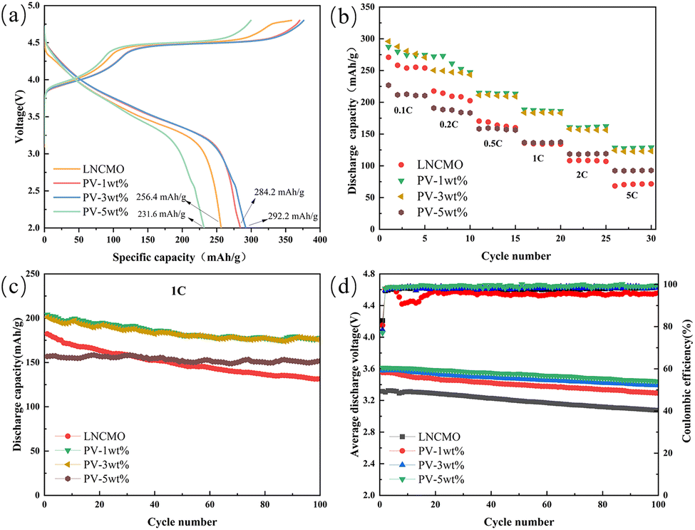 | ||
| Fig. 8 (a) The initial charge–discharge profiles and (b) rate performance of LNCMO, PV-1wt%, PV-3wt%, and PV-5wt%. (c) Cycle performance of all samples at 1.0C. (d) The medium discharge voltage during cycling. | ||
The rate capabilities of LNCMO, PV-1wt%, PV-3wt%, and PV-5wt% are shown in Fig. 8b. Cells were tested from 0.1 to 5C between 2.0 and 4.8 V, sustaining each rate for five cycles. The rate performance shows a significant improvement via surface modification. At 5C, the discharge specific capacities of LNCMO, PV-1wt%, PV-3wt%, and PV-5wt% were 68.3, 128.7, 124.2, and 92.3 mA h g−1, respectively. The better high-current performance of PV-1wt% and PV-3wt% is derived from their submicron single-crystal structure and the ultrathin fast ionic conductor layer, which are beneficial for the intercalation and deintercalation of lithium ions. The improvement effect of PV-5wt% was less than those of PV-1wt% and PV-3wt% because of the aggregation of single-crystal particles caused by excessive coating.
The cycling performance of the samples at 1C is shown in Fig. 8c. The initial discharge specific capacities of LNCMO, PV-1wt%, PV-3wt%, and PV-5wt% were 182.3, 204, 201.2, and 156.8 mA h g−1, respectively, and the capacity retention rates after 100 cycles were 72.2, 86.8, 87.7, and 96.8%. It is evident that the modified samples exhibit better cycling performance, and as the amount of coating increases, the capacity retention rate also increases. These results indicate that the coating layer can effectively prevent side reactions between the active materials and electrolytes. Moreover, as shown in Table 2, the cycling performance of the 3 wt% phosphorus–vanadium modified LNCMO in this study is competitive when compared with recent literature reports.
| Material | Modified method | Capacity retention | Ref. |
|---|---|---|---|
| Li1.2Ni0.13Co0.13Mn0.54O2 | Mg doped | 83%@1C@100 cycles | 43 |
| Li1.2Ni0.13Co0.13Mn0.54O2 | Na doped | 85.5%@1C@100 cycles | 44 |
| Li1.2Ni0.13Co0.13Mn0.54O2 | Mg, Al, and La co-doped | 83%@1C@100 cycles | 45 |
| Li1.2Ni0.13Co0.13Mn0.54O2 | Fe3+ doped | 87.1%@1C@100 cycles | 46 |
| Li1.2Ni0.13Co0.13Mn0.54O2 | CoAl2O4 coated | 81.33%@1C@100 cycles | 47 |
| Li1.2Ni0.133Co0.133Mn0.534O2 | Na+ doped | 76.5%@1C@100 cycles | 48 |
| Li1.2Ni0.13Co0.13Mn0.54O2 | Li3V2(PO4)3 coated | 87.7%@1C@100 cycles | This work |
Fig. 8d shows the average discharge voltage and coulombic efficiency after 100 cycles at a current density of 1C over a voltage range of 2.0–4.8 V. The initial average discharge voltages of LNCMO, PV-1wt%, PV-3wt%, and PV-5wt% were 3.32, 3.55, 3.58, and 3.61 V, respectively, and after 100 cycles, the average discharge voltages were 3.08, 3.29, 3.39, and 3.44 V, representing decays by 0.24, 0.26, 0.19, and 0.17 V. Voltage attenuation during cycling is one of the limiting factors for the commercial application of lithium-rich cathodes.49,50 Usually, voltage attenuation is attributed to the continued structural transition of materials from a layered to a spinel structure.51–53 The voltage attenuation of PV-3wt% and PV-5wt% are effectively suppressed. This can be attributed to the formation of a spinel layer induced by structural changes on the material surface, which has been proven to effectively suppress voltage decay.33 However, the voltage attenuation of PV-1wt% did not change significantly, which may be due to insufficient coverage that cannot cause structural changes on the material surface.
The CV curves of the first three charge–discharge cycles are shown in Fig. 9 to explore the redox reactions. The test was conducted between 2.0 and 4.8 V at a scanning rate of 0.1 mV s−1. During the initial charging process, the four electrodes exhibit two obvious peaks at approximately 4 and 4.59 V. The first oxidation peak at 4 V corresponds to the removal of Li+ from the lithium layer, where Ni2+ and Co3+ is oxidized to Ni4+ and Co4+, respectively.54,55 The second oxidation peak at 4.59 V is due to the release of Li+ ions in the layered Li2MnO3 to form Li2O, resulting in the irreversible loss of oxygen. During the discharge process, the peaks at 4.4 and 3.7 V are related to the reduction of Ni4+/Co4+.56,57 In the next two cycles, all oxidation and reduction peaks shifted toward lower voltages. However, PV-3wt% exhibits a better overlap ratio and a smaller voltage difference compared to PV-1wt% and PV-5wt%, indicating that it suppresses the voltage decay. This suggests that PV-3wt% possesses a stable structure and good electrochemical redox reversibility.58
 | ||
| Fig. 9 CV curves of the initial three cycles of (a) LNCMO, (b) PV-1wt% (c) PV-3wt%, and (d) PV-5wt%. | ||
The electrochemical impedance spectroscopies (EIS) in Fig. 10a and c describe the changes of SEI impedance (Rsf) and charge transfer resistance (Rct) before cycle and after 100 cycles. The equivalent circuit (Fig. 10 inset) was obtained by fitting the experimental data in Fig. 10. Rs is the uncompensated ohmic resistance between the cathode and anode in the battery system.59 Rsf is the resistance of Li ion diffusion in the region of the surface layer, Rct is charge transfer resistance and W is associated with the solid-state diffusion of Li ions in the bulk crystal.60 Q is defined as constant phase elements (generalized capacitances). The values of parameters Rsf and Rct calculated by the Zsimpwin software fitting are summarized in Table 3. The Rsf of the coated material was lower than that of LNCMO because of the Li3V2(PO4)3 coating provided a rapid pathway for Li+ diffusion. However, after 100 cycles, the Rsf of LNCMO, PV-1wt%, PV-3wt%, and PV-5wt% increased by approximately 138.40, 92.66, 19.99, and 168.46 Ω, respectively. Similarly, after 100 cycles, the Rct values of LNCMO, PV-1wt%, PV-3wt%, and PV-5wt% increased by approximately 245.50, 522.04, 171.90, and 488.06 Ω, respectively. It is evident that the increases in Rsf and Rct for PV-3wt% before and after cycling are significantly lower than those for PV-1wt%, and PV-5wt%. Owing to its minimal coating amount, PV-1wt% did not show a significant improvement in Rsf and Rct compared to LNCMO. The poor Rsf and Rct of PV-5wt% may be attributed to the excessively thick coating, which caused the aggregation of single-crystal particles, as observed in the SEM images (Fig. 4). The increase in the Rs and Rct of PV-3wt% during the cycling process was greatly suppressed, indicating that an appropriate amount of coating effectively hindered the side reactions between the electrode and electrolyte and inhibited the formation of the spinel structure.
 | ||
| Fig. 10 EIS plots (a) before and (c) after 100 cycles. The profiles of Z′ vs. ω−1/2 (b) before cycling and (d) after 100 cycles. | ||
| Sample | Before the 1st cycle | After the 100th cycle | |||
|---|---|---|---|---|---|
| Rsf (Ω) | Rct (Ω) | DLi+ (cm2 s−1) | Rsf (Ω) | Rct (Ω) | |
| LNCMO | 32.900 | 594.500 | 3.14 × 10⁻¹⁵ | 171.300 | 840.000 |
| PV-1wt% | 14.340 | 76.760 | 2.96 × 10⁻¹³ | 107.000 | 598.800 |
| PV-3wt% | 20.670 | 112.400 | 1.64 × 10⁻¹³ | 40.658 | 284.300 |
| PV-5wt% | 14.810 | 274.500 | 5.45 × 10⁻¹⁵ | 183.269 | 762.560 |
According to the linear relationship between Z′ and ω−1/2, as shown in Fig. 9b, the following equation was used to calculate the lithium-ion diffusion coefficient:61
 | (1) |
| Z′ = Rs + Rct + σω−1/2 | (2) |
To further explain the cycling stability of the electrode, SEM images of LNCMO and PV-3wt% after 100 cycles are shown in Fig. 11. After 100 cycles, the PV-3 wt% sample still had a single-crystal morphology, whereas the LNCMO sample barely maintained a single-crystal morphology. The surface of LNCMO gradually became dispersed with small particles owing to the lack of a coating layer, which further led to volume expansion. The reason for the good rate performance and cycle performance of PV-3wt% may be that the coating layer effectively maintained the structure of LNCMO and alleviated the volume change during the charge and discharge cycles.
 | ||
| Fig. 11 SEM images of (a) LNCMO and (b) PV-3wt% electrodes after cycling. | ||
4 Conclusions
In summary, we prepared a lithium-rich manganese-based material (LNCMO) with a single-crystal structure using the sol–gel method and ball milling technique and successfully coated it with a Li3V2(PO4)3 layer. Moreover, a spinel phase and oxygen vacancies were formed between the bulk material and coating layer during the coating process. This multilayer structure effectively improves the electrochemical performance of LNCMO. The modified sample PV-3wt% delivered the best comprehensive electrochemical performance. PV-3wt% exhibited an initial discharge specific capacity of 292.2 mA h g−1 at 0.1C, with an initial coulombic efficiency of 77.7%. In contrast, the discharge specific capacity and initial coulombic efficiency of LNCMO were 256.4 mA h g−1 and 71.5%, respectively. After 100 cycles at 1C, the discharge specific capacity of LNCMO and PV-3wt% were 176.4 and 131.6 mA h g−1, respectively, and the capacity retention rate increased from 72.2% to 87.7%. Furthermore, after 100 cycles, the average discharge midpoint voltage decay of LNCMO and PV-3wt% decreased from 2.4 to 1.9 mV per cycle, respectively. The rate performance at high rates was also significantly improved through surface modification, even at 5C, the discharge specific capacity of PV-3wt% was 124.2 mA h g−1 compared to 68.3 mA h g−1 for LNCMO. The Li+ diffusion coefficient of the PV-3wt% electrode (1.64 × 10⁻¹³ cm2 s−1) is 52 times that of the LNCMO electrode (3.14 × 10⁻¹⁵ cm2 s−1). These results indicate that coating single-crystal LNCMO surfaces with phosphorus–vanadium compounds is an effective solution to address capacity and voltage degradation, making it suitable for high-performance LNCMO applications.Data availability
The data supporting this article are all included in the manuscript.Author contributions
Baijun Song: writing – original draft, investigation, data curation. Fei Ma: writing – review & editing, supervision, resources, funding acquisition. Wei Ding: formal analysis. Jingkui Qu: funding acquisition, formal analysis.Conflicts of interest
The authors declare that there is no conflict of interest regarding the publication of this paper.Acknowledgements
This work was supported financially by Guizhou Provincial Science Technology Projects (Qiankehejichu-ZK [2022] Yiban 531), Foundation of Liupanshui Normal University (LPSSYKYJJ202005), Liupanshui Normal University Scientific Research and Cultivation Projects (LPSSYLPY202334), Guizhou Provincial Youth Talent Development Project (QianjiaoheKYzi [2022] 052), and Liupanshui Science and Technology Development Project ([2023]520202023028).Notes and references
- J. Feng, Y.-S. Jiang, F.-D. Yu, W. Ke, L.-F. Que, J.-G. Duh and Z.-B. Wang, J. Energy Chem., 2022, 66, 666–675 CrossRef CAS
.
- Y. Fan, W. Zhang, Y. Zhao, Z. Guo and Q. Cai, Energy Storage Mater., 2021, 40, 51–71 CrossRef
- Z. Zhou, T. Wang, A. Mateen, J. Li, X. Chen, W. Yan, A. Mujear, Y. Shao, J. Chen, X. Wang, C. Liu, G. Gao, Y. Mei, G. Wu and Z. Bao, J. Energy Storage, 2025, 115, 115997 CrossRef
- J.-J. Marie, R. A. House, G. J. Rees, A. W. Robertson, M. Jenkins, J. Chen, S. Agrestini, M. Garcia-Fernandez, K.-J. Zhou and P. G. Bruce, Nat. Mater., 2024, 23, 818–825 CrossRef CAS PubMed
- S. Liu, H. Yue, Y. Mo, L. Luo, X. Wu, S. Yang, Y. Huang and G. Yuan, RSC Adv., 2024, 14, 26142–26151 RSC
- W. Hua, S. Wang, M. Knapp, S. J. Leake, A. Senyshyn, C. Richter, M. Yavuz, J. R. Binder, C. P. Grey, H. Ehrenberg, S. Indris and B. Schwarz, Nat. Commun., 2019, 10, 5365 CrossRef PubMed
- X. Gou, Z. Hao, Z. Hao, G. Yang, Z. Yang, X. Zhang, Z. Yan, Q. Zhao and J. Chen, Adv. Funct. Mater., 2022, 32, 2112088 CrossRef CAS
- H. Cui, H. Li, J. Liu, Y. Zhang, F. Cheng and J. Chen, Inorg. Chem. Front., 2019, 6, 1694–1700 RSC
- Y. Wang, W. Yu, L. Zhao, A. Wu, A. Li, X. Dong and H. Huang, Electrochim. Acta, 2023, 462, 142664 CrossRef CAS
- C. Lu, S. Yang, H. Wu, Y. Zhang, X. Yang and T. Liang, Electrochim. Acta, 2016, 209, 448–455 CrossRef CAS
- W. Wang, H. Hanzawa, K. Machida, K. Miyazaki and T. Abe, Electrochemistry, 2022, 90, 017008 CrossRef CAS
- X. Liu, Q. Su, C. Zhang, T. Huang and A. Yu, ACS Sustainable Chem. Eng., 2016, 4, 255–263 CrossRef CAS
- S. Alagar, M. Ganesan, C. Karuppiah, C.-C. Yang, V. Bagchi and S. Piraman, ACS Appl. Energy Mater., 2023, 6, 622–635 CrossRef CAS
- Z. Li, C. Guo, S. Cao, H. Li, J. Chen, L. Wu, R. Wang, Y. Bai and X. Wang, J. Alloys Compd., 2024, 984, 173954 CrossRef CAS
- J. Wang, X. He, E. Paillard, N. Laszczynski, J. Li and S. Passerini, Adv. Energy Mater., 2016, 6, 1600906 CrossRef
- K. Ku, J. Hong, H. Kim, H. Park, W. M. Seong, S.-K. Jung, G. Yoon, K.-Y. Park, H. Kim and K. Kang, Adv. Energy Mater., 2018, 8, 1800606 CrossRef
- G. Sun, C. Zhao, F.-D. Yu, R. Yu, J. Wang, J. Zhou, G. Shao, X. Sun and Z.-B. Wang, Nano Energy, 2021, 79, 105459 CrossRef CAS
- M. Zhou, J. Zhao, X. Wang, J. Shen, J.-L. Yang, W. Tang, Y. Deng, S.-X. Zhao and R. Liu, RSC Adv., 2022, 12, 32825–32833 RSC
- L. Wu, S. Shi, X. Zhang, J. Liu, D. Chen, H. Ding and S. Zhong, Mater. Lett., 2015, 152, 228–231 CrossRef CAS
- C. Jiao, M. Wang, B. Huang, M. Zhang, G. Xu, Y. Liu, Y. Zhao and X. Hu, J. Alloys Compd., 2023, 937, 168389 CrossRef CAS
- R. Etefagh, S. M. Rozati and H. Arabi, Appl. Phys. A: Mater. Sci. Process., 2020, 126, 814 CrossRef CAS
- N. V. Kosova, O. A. Podgornova, I. A. Bobrikov, V. V. Kaichev and A. V. Bukhtiyarov, Mater. Sci. Eng., B, 2016, 213, 105–113 CrossRef CAS
- L. Li, M. Xu, Z. Chen, X. Zhou, Q. Zhang, H. Zhu, C. Wu and K. Zhang, Electrochim. Acta, 2015, 174, 446–455 CrossRef CAS
- C. Song, W. Feng, X. Wang and Z. Shi, Ionics, 2020, 26, 661–672 CrossRef CAS
- C. Zhang, P. Hou, X. Shi, D. Song, J. Song and L. Zhang, RSC Adv., 2015, 5, 36015–36021 RSC
- D. Dai, B. Wang, B. Li, F. Li, X. Wang, H. Tang and Z. Chang, RSC Adv., 2016, 6, 96714–96720 RSC
- Z. Li, B. Guo, Y. Chen, J. Chen, Z. Ma, X. Liu, J. Yang, Y. Chen, Y. Huang, M. Wang and X. Li, J. Power Sources, 2021, 487, 229410 CrossRef CAS
- X. Zhang, C. Yu, X. Huang, J. Zheng, X. Guan, D. Luo and L. Li, Electrochim. Acta, 2012, 81, 233–238 CrossRef CAS
- R. Yu, X. Zhang, T. Liu, L. Yang, L. Liu, Y. Wang, X. Wang, H. Shu and X. Yang, ACS Appl. Mater. Interfaces, 2017, 9, 41210–41223 CrossRef CAS PubMed
- W. Liu, J. Li, W. Li, H. Xu, C. Zhang and X. Qiu, Nat. Commun., 2020, 11, 3629 CrossRef CAS PubMed
- X.-P. Zhang, H.-J. Guo, X.-H. Li, Z.-X. Wang, W.-J. Peng and L. Wu, Chem. J. Chin. Univ., 2012, 33, 236–242 CAS
- J. Han, H. Zheng, Z. Hu, X. Luo, Y. Ma, Q. Xie, D.-L. Peng and G. Yue, Electrochim. Acta, 2019, 299, 844–852 CrossRef CAS
- B. Qiu, M. Zhang, L. Wu, J. Wang, Y. Xia, D. Qian, H. Liu, S. Hy, Y. Chen, K. An, Y. Zhu, Z. Liu and Y. S. Meng, Nat. Commun., 2016, 7, 12108 CrossRef CAS
- R. H. Sclar, E. Evenstein, S. Haber, S. Maiti, T. Sharabani, M. Leskes and M. Noked, Chem. Mater., 2019, 31, 3840–3847 CrossRef
- K. Liu, Q. Zhang, S. Dai, W. Li, X. Liu, F. Ding and J. Zhang, ACS Appl. Mater. Interfaces, 2018, 10, 34153–34162 CrossRef CAS
- J. Kim, H. Ma, H. Cha, H. Lee, J. Sung, M. Seo, P. Oh, M. Park and J. Cho, Energy Environ. Sci., 2018, 11, 1449–1459 RSC
- G. Sun, F.-D. Yu, L.-F. Que, L. Deng, M.-J. Wang, Y.-S. Jiang, G. Shao and Z.-B. Wang, Nano Energy, 2019, 66, 104102 CrossRef CAS
- M. Zhao, Y. Wang, Y. Wang, S. Liu, Z. Chen, F. Yong, P. Qian, S. Yang, Q. Huang and Z. Ning, J. Alloys Compd., 2024, 983, 173822 CrossRef CAS
- Y. Chen, D. Zhang, X. Bian, X. Bie, C. Wang, F. Du, M. Jang, G. Chen and Y. Wei, Electrochim. Acta, 2012, 79, 95–101 CrossRef CAS
- C. Lin, Y. Zhang, L. Chen, Y. Lei, J. Ou, Y. Guo, H. Yuan and D. Xiao, J. Power Sources, 2015, 280, 263–271 CrossRef CAS
- H. Yang, H. He, X. Xia, G. Wang, L. Liu, H. Fang, J. Wang, X. Hu and G. Zhou, J. Solid State Chem., 2023, 326, 124210 CrossRef CAS
- X. Jin, Q. Xu, H. Liu, X. Yuan and Y. Xia, Electrochim. Acta, 2014, 136, 19–26 CrossRef CAS
- Z. Huang, X. Li, Y. Liang, Z. He, H. Chen, Z. Wang and H. Guo, Solid State Ionics, 2015, 282, 88–94 CrossRef CAS
- S. Chen, Z. Chen, M. Xia, C. Cao and Y. Luo, ACS Appl. Energy Mater., 2018, 1, 4065–4074 CrossRef CAS
- Z. Zhou, T. Wang, A. Mateen, J. Li, X. Chen, W. Yan, A. Mujear, Y. Shao, J. Chen, X. Wang, C. Liu, G. Gao, Y. Mei, G. Wu and Z. Bao, J. Energy Storage, 2025, 115, 115997 CrossRef
- T. Liang, W. Zeng, L. Yang, S. Liu, Y. Huang, H. He, X. Chen and A. He, J. Alloys Compd., 2022, 910, 164862 CrossRef CAS
- L. Gao, Y. Su, Y. Zou, Y. Wang, B. Zhu, Y. Ma and L. Chen, J. Electrochem. Soc., 2024, 171, 020504 CrossRef CAS
- Y. Zhou, W. Shan, X. Hou, K. Lam, X. Zhao, X. Liu and Y. Wu, Solid State Ionics, 2020, 350, 115326 CrossRef CAS
- H. Chen, J. Ma, F. Liu and M. Yao, Chem.–Eur. J., 2023, 29, e202302569 CrossRef CAS PubMed
- Z. Hao, X. Gou, H. Ma, Z. Yang, Z. Hao, G. Yang, Y. Lu, Q. Zhao, H. Jin, Q. Zhang, Z. Yan and J. Chen, Sci. China Mater., 2023, 66, 3424–3432 CrossRef CAS
- S. Shi, S. Zhang, Z. Wu, T. Wang, J. Zong, M. Zhao and G. Yang, J. Power Sources, 2017, 337, 82–91 CrossRef CAS
- Y. Xu, E. Hu, F. Yang, J. Corbett, Z. Sun, Y. Lyu, X. Yu, Y. Liu, X.-Q. Yang and H. Li, Nano Energy, 2016, 28, 164–171 CrossRef CAS
- K. Ku, J. Hong, H. Kim, H. Park, W. M. Seong, S. Jung, G. Yoon, K. Park, H. Kim and K. Kang, Adv. Energy Mater., 2018, 8, 1800606 CrossRef
- W. Hua, S. Wang, M. Knapp, S. J. Leake, A. Senyshyn, C. Richter, M. Yavuz, J. R. Binder, C. P. Grey, H. Ehrenberg, S. Indris and B. Schwarz, Nat. Commun., 2019, 10, 5365 CrossRef
- X. Feng, Z. Yang, D. Tang, Q. Kong, L. Gu, Z. Wang and L. Chen, Phys. Chem. Chem. Phys., 2015, 17, 1257–1264 RSC
- Y. Liu, Z. Yang, J. Zhong, J. Li, R. Li, Y. Yu and F. Kang, ACS Nano, 2019, 13, 11891–11900 CrossRef CAS
- Q. Liu, T. Xie, Q. Xie, W. He, Y. Zhang, H. Zheng, X. Lu, W. Wei, B. Sa, L. Wang and D.-L. Peng, ACS Appl. Mater. Interfaces, 2021, 13, 8239–8248 CrossRef CAS
- C. Huang, Z. Wang, Z.-Q. Fang, S.-X. Zhao and L. Ci, J. Power Sources, 2021, 499, 229967 CrossRef CAS
- Y. Sun, L. Zhang, S. Dong, J. Zeng, Y. Shen, X. Li, X. Ren, L. Ma, C. Hai and Y. Zhou, Electrochim. Acta, 2022, 414, 140169 CrossRef CAS
- Y. Sun, L. Zhang, Y. Zhou, Y. Shen, C. Hai, X. Li, J. Zeng, X. Ren, L. Ma, X. Zhang, S. Dong and G. Qi, J. Electrochem. Soc., 2018, 165, A333 CrossRef CAS
- T. Zhao, Y. Meng, R. Ji, F. Wu, L. Li and R. Chen, J. Alloys Compd., 2019, 811, 152060 CrossRef CAS
| This journal is © The Royal Society of Chemistry 2025 |