
 Open Access Article
 This Open Access Article is licensed under a Creative Commons Attribution-Non Commercial 3.0 Unported Licence
Impact of Dy on the microstructural, electrical, and magnetic properties of topological Fe1.4Bi0.6Y0.5Se2.5−x nanocrystals
Amany M. El Nahrawy *a,
Hamdia A. Zayedb,
Somaya M. M. Al-Hindaweyb and
Ahmed I. Ali*cd
*a,
Hamdia A. Zayedb,
Somaya M. M. Al-Hindaweyb and
Ahmed I. Ali*cd
aSolid-State Physics Department, Physics Research Institute, National Research Centre, 33 El-Bohouth St., Dokki, Giza 12622, Egypt. E-mail: amany_physics_1980@yahoo.com; am.elnahrawy@nrc.sci.eg
bPhysics Department, Faculty of Science, Art and Education for Women, Ain Shams University, 11722 Cairo, Egypt
cBasic Science Department, Faculty of Technology and Education, Helwan University, Saray–El Qoupa, El Sawah Street, 11281 Cairo, Egypt. E-mail: Ahmed_Ali_2010@techedu.helwan.edu.eg
dDepartment of Mechanical Engineering (Integrated Engineering Program), Kyung Hee University, 1732 Deogyeong-Daero, Yongin, Gyeonggi 17104, Republic of Korea
First published on 9th April 2025
Abstract
Nanoparticles of Dy-doped Fe1.4Bi0.6Y0.5Se2.5−x (x = 0, 0.1, 0.2, 0.3) were synthesized using the sol–gel method. The effects of Dy doping on the microstructural, thermal, magnetic, and electrical properties of Fe1.4Bi0.6Y0.5Se2.5−x nano-crystallites were investigated. X-ray diffraction (XRD) analysis confirmed higher crystallinity in undoped Fe1.4Bi0.6Y0.5Se2.5. At higher Dy concentrations (x: 0.1, 0.2, 0.3), a few peaks corresponding to the DyFeO3 phase appeared. Morphological analyses (SEM/TEM) and FTIR spectra revealed Dy-induced microstructural modifications, including an increase in particle size to 25–27 nm and alterations in Bi–O–Dy vibrations. Thermal analysis demonstrated dehydration-induced weight loss and excellent thermal stability up to 600 °C. Magnetic measurements indicated a transition from ferromagnetic to superparamagnetic with Dy doping, alongside superparamagnetic tendencies at higher Dy concentrations. Electrical measurements showed a transition from semiconducting to metallic behavior, with conductivity increasing at higher frequencies and temperatures, suggesting thermally activated conduction mechanisms. These findings confirm that Dy3+ incorporation significantly influences the internal structure of Bi0.6Fe1.4Se2.5Y0.5 nanoceramics, enhancing their magnetoelectric properties. The improved structural, thermal, magnetic, and electrical characteristics make Dy-doped Bi0.6Fe1.4Se2.5Y0.5 nanoceramics promising candidates for applications in microelectronics, topological quantum devices, and spintronics.
1 Introduction
Topological insulators (3D-TIs) exhibit a non-trivial topology of electronic bands, characterized by topologically protected metallic surface states and an insulating nature in the bulk electronic configuration.1,2 Bismuth selenide belongs to this family and exhibits such extraordinary behavior due to spin–orbit coupling (SOC), which is responsible for closing the bulk bandgap at the surface. The surface states show a linear, Dirac-like dispersion, and the carriers that occupy these states exhibit spin-momentum locking.3–6 These features make Bi2Se3-based nanostructures promising candidates for next-generation technologies, as quantum computation, spintronics, and energy-efficient electronic devices. Doping topological nanoceramics with magnetic dopants, particularly with some rare-earth elements, has opened new approaches for tailoring their properties.Further, Bi2Se3 is a well-known topological insulator with excellent surface conductivity and spin-polarized states, making it useful for spintronics and quantum computing. However, it is nonmagnetic in its pure form, requiring transition metal doping (Fe, Mn, Cr) to induce magnetism, which can disrupt its topological states. It suffers from structural instability due to weak van der Waals bonding, is difficult to modify, and is sensitive to Se vacancies, leading to unwanted bulk conductivity. While a good thermoelectric material, it decomposes at ∼700 K, limiting high-temperature applications. Despite being a strong topological insulator with a single Dirac cone, heavy doping or structural disturbances can drive it into a trivial insulator state.1,2,7
However, Bi0.6Fe1.4Se2.5Y0.5 offers advantages over Bi2Se3, including intrinsic ferromagnetism from Fe3+ ions and tunable magnetic ordering via Y3+ doping, making it ideal for spintronics and quantum computing. It features enhanced crystallinity, stability, and conductivity, with semiconducting-to-metallic transitions and improved defect resistance for optimized transport properties. Additionally, it exhibits high thermal stability (∼600 °C), enabling high-temperature applications. Its unique magnetism-topology interplay supports QAHE, axion insulator states, and Weyl phases, making it a promising candidate for next-gen quantum and spintronic devices.8–12
Magnetic nanoceramics exhibit a magnetic moment when subjected to an external magnetic field.13,14 In contrast to single-phase magnetic crystals, such as Cr2O3,15–17 magnetic composites are composed of different chemical elements, often including metals such as Fe, Mn, Co, Ni, and Cr. The magnetic behavior of these composites is not solely a result of their intrinsic properties but rather arises from the tensor properties of the material.18–21 When an external magnetic field is applied to a composite material, the magnetic component undergoes magnetostrictive deformation, inducing strain on the piezoelectric component and generating dielectric polarization. This indirect two-phase strain coupling enables flexibility in optimizing the magnetostrictive phase, piezoelectric phase, and their interface, thereby enhancing the magnetic and electric responses of the composite.19,20,22 Magnetic nanocomposites are particularly attractive for industrial applications, such as sensors (e.g., for ultralow magnetic field detection), water treatment, drug delivery, and electrochemical processes that require magnetic responsiveness at room temperature.23,24 Tim P. Comyn et al. have worked on improving the magnetic and electrical properties of co-doped Bi2Se3 using various cations, including lanthanum, iron, cerium, nickel, and rare earth elements.25,26
The study of thermal, optical, and magnetic properties in nanoceramics has gained significant attention due to their potential applications in diverse fields such as electronics, energy storage, and spintronics. Among these nanoceramics, topological insulators – especially those based on bismuth selenide (Bi2Se3)-have emerged as promising candidates due to their unique electronic properties and robustness against impurities. Incorporating rare-earth elements, such as dysprosium (Dy), into these systems can significantly alter their magnetic behavior and thermal stability, making them suitable for advanced technological applications.
Dysprosium (Dy), known for its great ionic radius and exclusive magnetic characteristics, can encourage novel structural and magnetic phases when combined into Bi2Se3-based structure. Such doping has been shown to adapt the crystallinity, thermal, magnetic behavior, and electrical features of topological insulators, increasing their potential applications in progressive technologies.27,28
Recent reports highlight the advantages of the sol–gel technique among various methods for preparing composite nanoceramics.29–32 The sol–gel method has proven to be operative, cost-effective, time-efficient, and versatile for preparing ceramic composites.33–35 It enables the introduction of higher dopant ratios into Bi-based systems and provides an effective approach to synthesizing nanoceramics under lower temperatures.36,37 However, the behavior of Bi2Se3-based systems prepared using this method has not been extensively studied and the behavior of Bi2Se3-based under lower temperatures prepared by this method has not been investigated in detail.38–40 Rare-earth element doping offers a promising avenue for tailoring the microstructural, magnetic, spectroscopic, and dielectric properties of three-dimensional topological insulators (3D-TIs).41,42 Dysprosium (Dy), with its large ionic radius and unique magnetic properties, has demonstrated potential for inducing novel phases and enhancing material functionality when doped into Bi-based systems. The introduction of Dy into Bi0.6Fe1.4Se2.5Y0.5 allows for the manipulation of its crystallinity, morphology, magnetic behavior, and dielectric performance, paving the way for advanced applications in spintronics and topological quantum devices.
In this study, we focus on doping rare-earth elements with smaller ionic radii, such as Dy, into Bi0.6Fe1.4Se2.5Y0.5 nanocrystallites to explore new applications and investigate the structural and electromagnetic properties of topological insulators. Specifically, Bi0.6Fe1.4Y0.5Se2.5−xDyx (where x = 0, 0.1, 0.2, and 0.3) was synthesized using the sol–gel method. The process seeks to incorporate Dy into Bi0.6Fe1.4Se2.5Y0.5 to study its effects on the material's physical, magnetic, and electrical properties, which is vital for discovering new applications in spintronics and microelectronics. The crystallization behavior and spectroscopic properties were analyzed using X-ray diffraction (XRD), high-resolution scanning electron microscopy (HR-SEM), and Fourier transform infrared (FT-IR) spectroscopy. Transmission electron microscopy (TEM) was employed to examine particle size and morphology. Thermal analyses (DSC) were performed at varying temperatures. Additionally, the magnetic moment-field dependence was studied at room temperature. A key objective of this work is to develop low-cost Bi0.6Fe1.4Se2.5Y0.5 nanoceramics with controllable particle sizes for various applications, as well as to induce a magnetic state within topological insulators.
2 Experimental work
2.1. Samples preparation
The base sample, Fe1.6Bi0.4Se3, was prepared using the sol–gel technique. High-purity raw materials were used, including bismuth(III) chloride (BiCl3, 98%, Sigma-Aldrich), iron(III) nitrate nonahydrate (Fe(NO3)3·9H2O, Sigma-Aldrich), and selenium oxide (SeO2, 98%, PubChem). The preparation process begins with dissolving these materials in a mixture of hydrochloric acid (HCl) and distilled water in a stoichiometric ratio of 2![[thin space (1/6-em)]](https://www.rsc.org/images/entities/char_2009.gif) :3. The solution was stirred magnetically at 100 °C for 2 hours to facilitate hydrolysis, resulting in a homogenous gel. Once the gel formation was complete, it was aged for 48 hours at room temperature, followed by drying at 300 °C for 10 hours to yield a fine nanomaterial powder. This nanopowder was then calcined in an air bath at 700 °C for 4 hours, with a heating rate of 10 °C min−1, to achieve crystallization.
:3. The solution was stirred magnetically at 100 °C for 2 hours to facilitate hydrolysis, resulting in a homogenous gel. Once the gel formation was complete, it was aged for 48 hours at room temperature, followed by drying at 300 °C for 10 hours to yield a fine nanomaterial powder. This nanopowder was then calcined in an air bath at 700 °C for 4 hours, with a heating rate of 10 °C min−1, to achieve crystallization.
To synthesize the Dy-doped samples, we utilized the base sample Fe1.6Bi0.4Se3 and incorporated yttrium oxide (Y2O3, 99.99%, Fluka AG) and dysprosium(III) oxide (Dy2O3, 99.9%, High Purity Chemicals) in stoichiometric proportions. Yttrium is often used to modify electrical properties, while dysprosium is known for its interesting magnetic characteristics. The specific compositions for Bi0.6Fe1.4Y0.5Se2.5−xDyx (where x = 0, 0.1, 0.2, and 0.3) samples were calculated based on the base formulation, enabling the targeted doping of Dy.
The prepared smart nanomagnetic topological Fe1.4Bi0.6Y0.5Se2.5−xDyx nano-crystallites were characterized using X-ray diffraction with (Malvern Panalytical B. V. (XRD)) diffractometer from the Netherlands, which uses CuKα radiation, with a wavelength of 1.5406 Å and a scanning rate of 2° min−1 (at 40 kV and 40 mA). Scherrer's equation, used to determine the crystal size (D), is expressed as:32,43–46

The microstructure examined using the field emission scanning electron microscope (SEM-JEOL IT 100) with a 15 kV accelerating voltage and the Transmission Electron Microscope (TEM; JEOL JEM-2100, JAPAN transmission electron microscope). A suspension of sample powder in a solution that is not soluble in it, is obtained, and the carbon grid is dipped in that solution to catch some particles that will be subjected to the electron beam.
A Fourier transform computerized infrared spectrometer (JASCO, FT/IR-6100, Japan) was used to measure the infrared absorption spectra of the produced samples at room temperature in the wavenumber range 400–4000 cm−1. The investigated samples were made by combining 2 mg KBr with 200 mg of prepared nanopowders, then applying a weighted pressure of 5 tons per cm2 to generate transparent homogenous discs. The infrared absorption measurements were taken right after the discs were prepared. Thermal analysis (differential scanning calorimetry (DSC)) for all samples was done using simultaneous DSC model SDT Q 600 spectrometer, USA, with scanning at a heating rate of 10 °C min−1. The M−H loop (magnetization as a function of applied magnetic field) is commonly calculated by measuring the induced electromotive force caused by flux variations (electromotive induction method). We employed a vibrating sample magnetometer (VSM) type Lake Shore, 7410 VSM, USA in the field range of −20000 G to +20000 G for this purpose. For ac electrical conductivity tests, all prepared samples were formed into discs with a diameter 0.5 cm and thickness 0.15 cm.47,48 It was covered with silver paste on both sides. The temperature range was used to test the ac electrical conductivity of the manufactured samples (313–473 K). A calibrated Chromel-Alumel thermocouple coupled to a (TCN4M-24R Aulonics-Korea) temperature controller was used to measure and control the sample temperature. A programmed automatic LCR bridge (Hioki, 3532-50) was utilized to assess ac electrical conductivity across a wide frequency range (50 Hz to 5 MHz).
3 Results and discussion
3.1. X-ray diffraction
At ambient temperature, phase identification was performed on Bi0.6Fe1.4Y0.5Se2.5−xDyx (x = 0.1, 0.2 and 0.3 mol%) nanocomposites calcined at 700 °C. Fig. 1(a and b) show the resulting X-ray diffraction (XRD) patterns of Bi0.6Fe1.4Y0.5Se2.5 and Bi0.6Fe1.4Y0.5Se2.5−xDyx (x = 0.1, 0.2 and 0.3 mol%), respectively, with data collected over the range of 2θ from 20° to 80°. The XRD pattern for the undoped Bi0.6Fe1.4Se2.5Y0.5 sample indicates high crystallinity, as shown in Fig. 1(a). The results align well with standard XRD cards for bismuth selenide oxide, bismuth ferrite, and yttrium selenite oxide (JCPDS file no. 73-1316, 86-1518, and 51-1102) at the plans (110), (105), (214), (131), (312) corresponding to the overlapping of these phases.12,49,50 These secondary phases indicate complex interactions that may enhance characteristics like magnetic behavior and thermal stability. These phases arise due to the synthesis conditions and the sol–gel process, which can lead to partial oxidation of the precursors. Upon doping with dysprosium (Dy) at concentrations of 0.1, 0.2, and 0.3 mol%, significant changes in the XRD patterns are observed, as shown in Fig. 1(b). These changes include the disappearance of some peaks, the appearance of new peaks, and a reduction in the intensity of certain peaks. These alterations confirm that Dy has been incorporated into the structure, introducing a rearrangement in the internal structure. The new peaks at 2θ: 26.39°, 32.64°, 47.05°, 58.5°, and 59.88° are characteristic of the bismuth ferrite phase.51,52 Additionally, two peaks, denoted by (*), are observed at lower intensities, corresponding to traces of Dy2O3. Peak broadening and slight shifts to the left are also noted. These changes can be attributed to the large ionic radius of Dy3+, which introduces mechanical stress to the structure. This stress leads to structural alterations such as peak shifting, broadening, and the formation of a new ferrite phase, DyFeO3.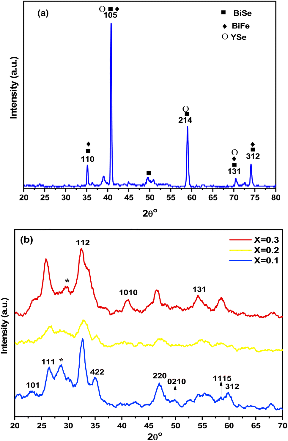 | ||
| Fig. 1 XRD patterns of (a) Bi0.6Fe1.4Se2.5Y0.5, and (b) Bi0.6Fe1.4Y0.5Se2.5−xDyx (x = 0.1, 0.2 and 0.3%) nanoceramics. | ||
The Dy atoms prove a progressive change in the local structure of Bi0.6Fe1.4Se2.5Y0.5 as the concentration of Dy3+ increases. These changes may result from modifications in the coordination of the Bi0.6Fe1.4Se2.5Y0.5 chains. Also, the topological units of Bi0.6Fe1.4Se2.5Y0.5, which play an essential role in generating the network, enable the incorporation of Dy oxide with higher concentrations. This, sequentially, leads to an increased propensity for crystallization. Furthermore, the separation and dispersion of Dy atoms to the grain boundaries enhance the formation of this novel phase. The crystal size (D) of the nanocrystalline samples was calculated using Scherrer's equation. For the undoped sample, the crystal size was found to be 33 nm, while for the sample, it was doped with 0.3 mol% Dy, it reduced to 3.42 nm. This decrease in crystal size is attributed to the larger ionic radius of Dy. The calculated phases and their corresponding Miller indices, along with the lattice parameters, are discussed in the findings section. The samples' crystallite sizes range from 34 nm to 37 nm. The doping of Fe ions caused a slight increase in crystallite size due to changes in ionic radii.
3.2. FE-SEM-EDX/TEM analysis
The surface morphology and grain size of Bi0.6Fe1.4Se2.5Y0.5 and Bi0.6Fe1.4Y0.5Se2.5−xDyx (x = 0.1, and 0.3 mol%) nano-powders were analyzed using scanning electron microscopy (SEM). High-resolution SEM images, shown in Fig. 2(a–c), were captured for the samples. The images reveal the high crystallinity of all samples, a result attributed to the sol–gel technique employed in their synthesis. Surface morphology analysis showed a high degree of nanoparticle agglomeration, with non-uniform shapes and larger voids segregated from the heterostructure surfaces. The rod-like morphology observed refers to elongated nanoparticle shapes (nano-rods) that appear in the SEM images. During the calcination, the sol–gel process tends to favor certain crystalline directions, leading to anisotropic growth and the formation of rod-like structures.32,53 Nanorods were observed across all diffused surfaces. Using the linear intercept technique (LIT) in SEM, the grain size was determined to be 15 nm for Bi0.6Fe1.4Se2.5Y0.5 and 25–27 nm for Bi0.6Fe1.4Y0.5Se2.5−xDyx (x = 0.1, and 0.3 mol%) nano-powders. The grain size increased with the addition of Dy, with higher Dy3+ concentrations resulting in larger grain sizes. | ||
| Fig. 2 SEM pictures (a) for Bi0.6Fe1.4Se2.5Y0.5, (b) for Bi0.6Fe1.4Y0.5Se2.4Dy0.1 and (c) for Bi0.6Fe1.4Y0.5Se2.2Dy0.3. | ||
Energy-dispersive X-ray spectroscopy (EDX) analysis was conducted to confirm the elemental composition of the nanoceramics. Fig. 3(a and b) present the EDX spectra for Bi0.6Fe1.4Se2.5Y0.5 and Bi0.6Fe1.4Y0.5Se2.2Dy0.3. The spectrum in Fig. 3(a) verifies the presence of Bi, Se, Fe, and Y in the undoped sample, while Fig. 3(b) confirms the inclusion of Dy alongside the original elements in the Dy-doped sample.
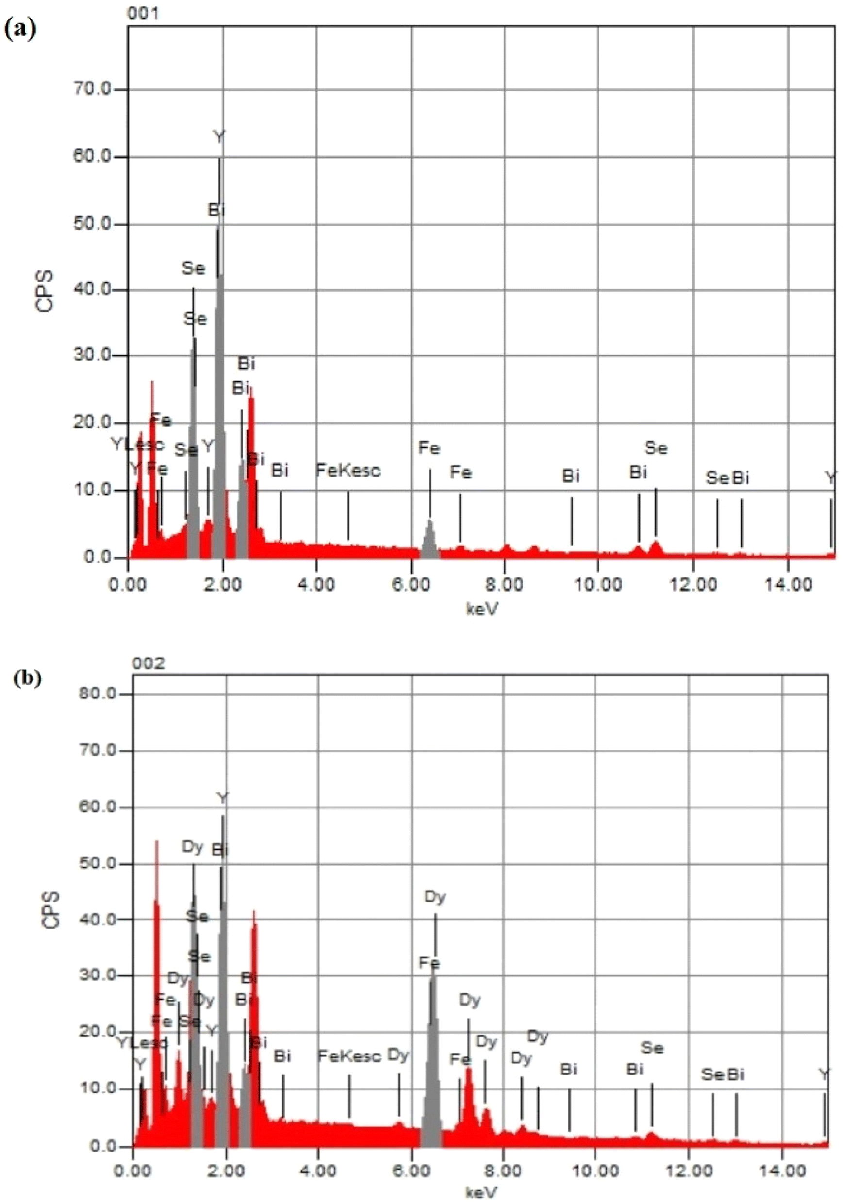 | ||
| Fig. 3 EDX pictures (a) for Bi0.6Fe1.4Se2.5Y0.5 and (b) for Bi0.6Fe1.4Y0.5Se2.2Dy0.3 samples. | ||
High-resolution transmission electron microscopy (TEM) images of Bi0.6Fe1.4Se2.5Y0.5 and Dy-doped nano-powders are displayed in Fig. 4(a–d). The TEM analysis highlights agglomerations of nanoscale particles with varying sizes, nano-spheres, and nano-rods in the undoped Bi0.6Fe1.4Se2.5Y0.5 sample (Fig. 4(a and b)). The average size of these nanoparticles ranges from 27 to 39 nm, while the nano-rods exhibit widths between 5 and 11 nm and lengths from 11 to 90 nm. The strong crystallinity of the sample is evident in Fig. 4(b), aligning with the XRD results discussed earlier. Doping 2 mol% Dy into Bi0.6Fe1.4Se2.5Y0.5 led to denser agglomerations, as shown in Fig. 4(c and d). These agglomerations include nano-spheres, nano-rods, and newly formed irregular-shaped nanoparticles, which confirm the successful incorporation of Dy into the structure. The presence of Dy is consistent with the appearance of a new phase observed in the XRD pattern. The estimated interplanar spacing for the Dy-doped sample is approximately 0.41 nm, as depicted in Fig. 4(c).
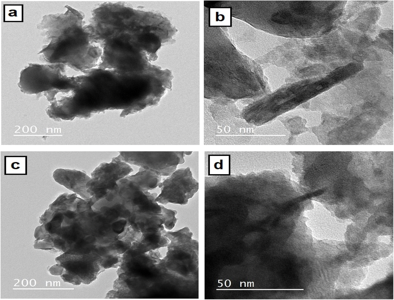 | ||
| Fig. 4 High-resolution TEM photographs for (a and b) Bi0.6Fe1.4Se2.5Y0.5 and (c and d) for Bi0.6Fe1.4Y0.5Se2.3Dy0.2 nano-powders. | ||
Overall, the particle distribution in the TEM images indicates an irregular size distribution among the prepared samples. The observed nanorod layer is believed to contribute to the enhanced crystallinity of the nanoceramics.
3.3. FT-IR analysis
Fig. 5(a–d) presents the infrared transmittance spectra of Bi0.6Fe1.4Se2.5Y0.5 and doped Bi0.6Fe1.4Y0.5Se2.5−xDyx (x = 0.1, 0.2 and 0.3 mol%) nanoparticles. A broadband observed in the range of 3600–2900 cm−1 and at 1631 cm−1 in all samples was ascribed to O–H stretching and bending vibrations, respectively, attributed to moisture absorbed from the atmosphere and chemicals used during the synthesis process.54,55 Additionally, peaks in the range of 1580–1350 cm−1 were assigned to carboxyl groups, likely due to CO2 absorption from the environment during synthesis56,57 | ||
| Fig. 5 FTIR spectrum for (a) Bi0.6Fe1.4Se2.5Y0.5, (b) Bi0.6Fe1.4Y0.5Se2.4Dy0.1, (c) Bi0.6Fe1.4Y0.5Se2.3Dy0.2, and (d) Bi0.6Fe1.4Y0.5Se2.2Dy0.3 samples. | ||
By comparing the spectra, it was found that the Bi0.6Fe1.4Se2.5Y0.5 sample (curve (a)) exhibited a broad peak at 1110 cm−1, attributed to Bi–O–metal vibrations.55 This peak's intensity decreased in the doped samples (curves (b, c, and d)), and the deformation was attributed to Dy incorporation, resulting in a Bi–O–Y vibration. Another prominent peak at 890 cm−1, observed in the Bi0.6Fe1.4Se2.5Y0.5 spectrum, was also attributed to Bi–O–metal vibrations, likely corresponding to Bi–O–Y.55,58 This peak disappeared upon Dy3+ ion doping in the Bi0.6Fe1.4Y0.5Se2.5−xDyx (x = 0.1, 0.2 and 0.3 mol%) samples, confirming structural disruption due to Dy incorporation. The spectral range of 800–400 cm−1 was dominated by metal–oxygen and metal–oxygen–metal vibrations.55,59 Enlarging this region and comparing patterns revealed significant deviations in Dy-doped samples from the undoped sample (Bi0.6Fe1.4Se2.5Y0.5), further indicating structural disruption.60,61 Peaks at 770 cm−1 and 700 cm−1 in Bi0.6Fe1.4Se2.5Y0.5 and Bi0.6Fe1.4Y0.5Se2.4Dy0.1 corresponded to Y–O–Bi/Fe and Y–O vibrations, respectively.54,62 In samples with x = 0.2 and x = 0.3, these peaks merged and shifted slightly to lower wavenumbers, confirming Dy3+ induced structural changes. Low-intensity peaks in the 580–535 cm−1 region appeared in the doped samples, attributed to Dy–O–metal vibrations, possibly representing Fe–O–Dy vibrations.59,63 These peaks confirmed the presence of a new phase (DyFeO3), consistent with the XRD results in Fig. 5(b). A peak at 530 cm−1, attributed to Fe–O vibrations, was observed in all samples. Upon doping with 0.1 mol% Dy, two additional peaks emerged at 514 cm−1 and 484 cm−1, assigned to Bi–O–Dy vibrations.59–61 These peaks shifted to lower wavenumbers with increasing Dy3+ concentration.63 Another new peak, at 457 cm−1, was observed in the doped samples but not in the undoped Bi0.6Fe1.4Se2.5Y0.5 sample, likely corresponding to Y–O–Fe vibrations. The peak at 449 cm−1, attributed to Fe–O vibrations in the undoped sample, was also detected in the doped samples.59 Peaks in the 400–470 cm−1 range in all spectra were ascribed to Y–O and Y–O–metal vibrations, likely corresponding to Y–O–Bi/Fe vibrations.64,65
3.4. Thermal analysis (DSC)
Differential scanning calorimetry (DSC) encompasses techniques designed to monitor changes in a sample's properties over a predetermined time or temperature in a specific environment. These techniques go beyond simple property tracking, as they analyze changes occurring during programmed temperature variations. Notably, the programmed temperature refers to the ambient (furnace) temperature, not the specimen's actual temperature.66 A wide range of methods are employed in DSC due to the diversity of properties that can be evaluated. Further heating up to 600 °C caused a gradual and minor mass decrease, linked to the release of residual moisture and solvents used during synthesis. The total weight loss did not exceed 9.5% across all samples, confirming their thermal stability up to 600 °C.67,68 Differential scanning calorimetry (DSC) was employed to examine phase transitions in the prepared samples. The resulting DSC thermograms are shown in Fig. (6). A peak around 43 °C was observed in all samples except for x = 0.1, where a peak appeared at approximately 27 °C. These peaks were attributed to the evaporation of humidity trapped in the samples during preparation. As the material was heated further, crystallization processes occurred around 164 °C, where molecules rearranged into more stable structures.69 Beyond these transitions, no further changes were observed up to 600 °C, indicating high thermal stability within the experimental range.70 | ||
| Fig. 6 DSC curves for Bi0.6Fe1.4Y0.5Se2.5−xDyx (x = 0.0, 0.1, 0.2 and 0.3 mol%) nanocrystallites as a function of temperatures. | ||
3.5. Magnetization (M–H) curves
Fig. 7(a–d) presents the magnetic hysteresis (M–H) loops of Bi0.6Fe1.4Y0.5Se2.5−xDyx (x = 0.0, 0.1, 0.2 and 0.3 mol%) nanocrystals measured at ambient temperature. These measurements were performed using a vibrating sample magnetometer (VSM) under an applied magnetic field of ±20 kOe. The observations and interpretations of the curves as flowing; the hysteresis loop of the undoped sample (x = 0.0, Fig. 7(a)) displays an S-like shape for undoped sample Bi0.6Fe1.4Se2.5Y0, characteristic of a material with a ferromagnetic nature. The ferromagnetic behavior can be attributed to the presence of Fe ions, which exhibit spontaneous magnetization due to strong exchange interactions between Fe3+ ions within the host matrix. Upon doping with Dy ions (x = 0.1, 0.2, and 0.3) (Fig. 7(b–d)), the hysteresis loops narrow significantly and lack moment saturation, signaling a transition from ferromagnetic to superparamagnetic behavior with increasing Dy content. The Dy-doped samples exhibit a superparamagnetic trend, as evidenced by the diminishing hysteresis and reduced remanent magnetization. This behavior suggests weaker magnetic ordering due to the presence of Dy ions. In the undoped sample, Fe ions exhibit ferromagnetic states due to their interaction and alignment of magnetic moments. However, in the presence of Dy ions, which have a larger ionic radius, this alignment is hindered. The presence of these larger ions can distort the crystal lattice, which in turn modifies the local environment around the Fe ions. However, after introducing Dy ions, the coupling between Y3+ and Dy3+ ions disrupt these interactions. The experimental data suggest that the interaction between Fe ions and rare-earth ions is inhibited by the coupling effects of yttrium and dysprosium ions, resulting in a shift to superparamagnetic behavior. Fe ions, though capable of forming ferromagnetic states, are unable to do so in the Dy-doped samples because the larger ionic radii of Dy3+ ions and the associated lattice distortions alter the magnetic interactions. The addition of Dy ions to Bi0.6Fe1.4Y0.5Se2.5−xDyx resulted in significant magnetic changes to the properties of the Bi0.6Fe1.4Se2.5Y0.5 nanocrystalline. The increasing Dy content induces the transition from ferromagnetic to superparamagnetic behavior, reflecting the complex interplay between Fe, Dy, and Y ions. The observed superparamagnetic tendency in Dy-doped samples further underscores the disrupted magnetic ordering in these nanocrystals.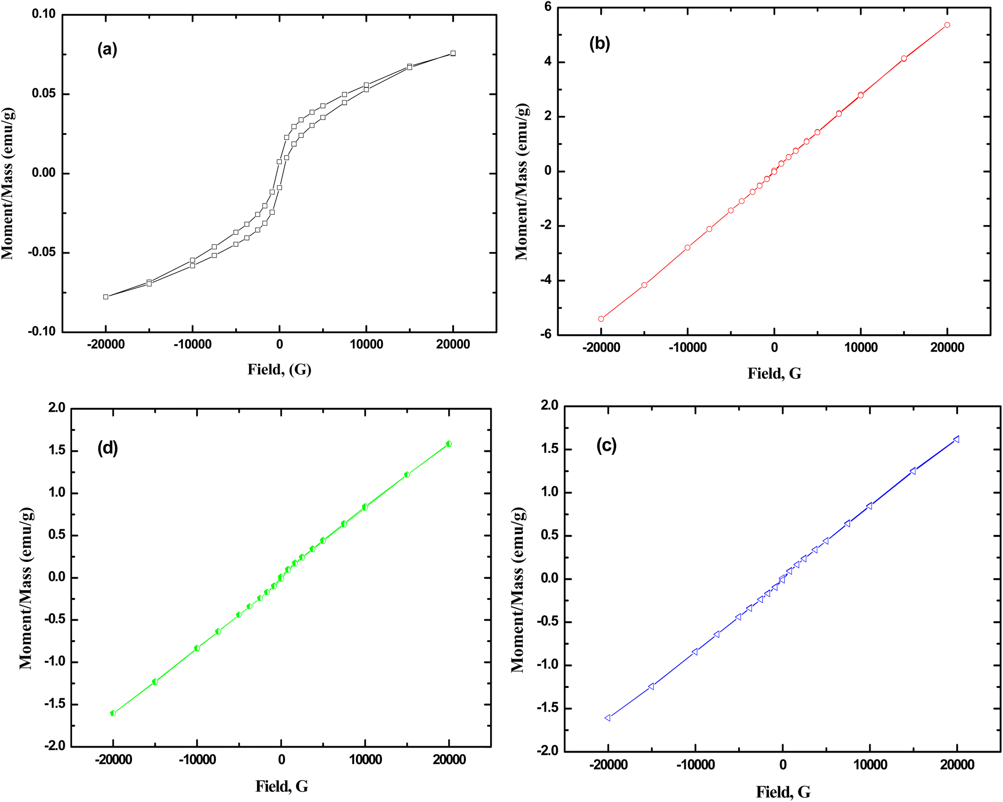 | ||
| Fig. 7 Magnetic moment as function of applied magnetic field of (a) Bi0.6Fe1.4Se2.5Y0.5, (b) Bi0.6Fe1.4Y0.5Se2.4Dy0.1, (c) Bi0.6Fe1.4Y0.5Se2.3Dy0.2 and (d) Bi0.6Fe1.4Y 0.5Se2.2Dy0.3 samples. | ||
3.6. Electrical conductivity
The AC electrical conductivity of samples is presented in Fig. (8). The experimental results display the frequency-dependent conductivity (ln σ) versus frequency (ln ω) for Bi0.6Fe1.4Se2.5−xY0.5Dyx nanocrystals (x = 0.0 x = 0.0 x = 0.0, 0.1, 0.2, and 0.3) at various temperatures ranging from 313 K to 473 K. The plots (a–d) correspond to the undoped and Dy-doped samples. All samples exhibit an increase in conductivity with increasing frequency and temperature, indicating thermally activated conduction mechanisms. The curves show non-linear behavior, suggesting the dominance of hopping or localized charge carriers at lower frequencies and a transition to band conduction at higher frequencies. As the Dy content increases (from x = 0.0 to x = 0.3), a noticeable shift in the conductivity trend is observed. The doped samples display slightly reduced conductivity at higher Dy concentrations, likely due to structural changes and increased scattering caused by Dy substitution. Additionally, the frequency-dependent behavior becomes more pronounced, reflecting the impact of Dy on charge carrier dynamics and the material's electronic structure. This behavior supports the idea that Dy doping modifies the electrical transport properties by disrupting the crystallinity and increasing defect density. | ||
| Fig. 8 Frequency and temperature dependence of total electrical conductivity (σtot) for (a) Bi0.6Fe1.4Se2.5Y0.5, (b) Bi0.6Fe1.4Y0.5Se2.4Dy0.1, (c) Bi0.6Fe1.4Y0.5Se2.3Dy0.2 and (d) Bi0.6Fe1.4Y0.5Se2.2Dy0.3 samples. | ||
Fig. 9(a–d) shows the total electrical conductivity (σtot) of Bi0.6Fe1.4Y0.5Se2.5−xDyx (x = 0.0, 0.1, 0.2, and 0.3 mol%) nanoceramics as a function of frequency at various temperatures. As can be seen from the figures, overall conductivity is frequency-dependent on high frequencies but frequency-independent (remains constant) at low frequencies for all samples. The overall conductivity of Dy-doped samples is lower than that of Bi0.6Fe1.4Se2.5Y0.5 samples in this group, which could be attributed to unbalanced ion substitution due to the ionic radius discrepancy.
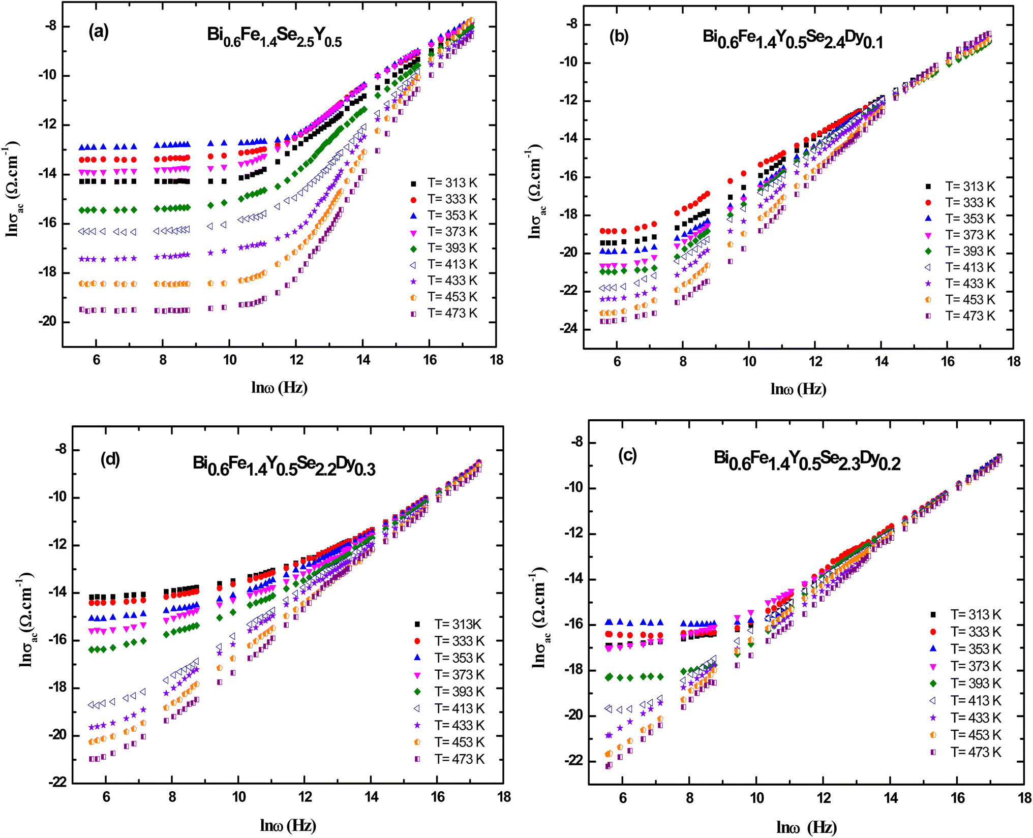 | ||
| Fig. 9 Frequency and temperature dependence of ac electrical conductivity (σac) for (a) Bi0.6Fe1.4Se2.5Y0.5, (b) Bi0.6Fe1.4Y0.5Se2.4Dy0.1, (c) Bi0.6Fe1.4Y0.5Se2.3Dy0.2 and (d) Bi0.6Fe1.4Y0.5Se2.2Dy0.3 samples. | ||
The ac conductivity is frequency independent for all samples in the low-frequency zone, which could be attributed to the dc conductivity contribution to the total conductivity, but frequency dependent in the high-frequency region, as seen in the figure. Furthermore, as the frequency was raised, the ac conductivities showed a change in slope to greater values. Hopping conduction was postulated to be dominated as a result of increased ac with increasing frequency because the hopping of charge carriers between defect sites is enhanced as the applied frequency increases.71
The values of the exponent (s) were derived from the slopes of the lines in Fig. 10(a–d) at various temperatures. Fig. 10(a–d) depicts the temperature dependence of (s) for Bi0.6Fe1.4Y0.5Se2.5−xDyx (x = 0.0, 0.1, 0.2, and 0.3 mol%) produced samples. For Bi0.6Fe1.4Se2.5Y0.5 and Bi0.6Fe1.4Y0.5Se2.4Dy0.1 samples, values of (s) declined with increasing temperature, reaching a minimum at T = 353 K for Bi0.6Fe1.4Se2.5Y0.5 and Bi0.6Fe1.4Y0.5Se2.4Dy0.1 samples, and T = 373 K for Bi0.6Fe1.4Y0.5Se2.3Dy0.2 and T = 373 and 393 K for Bi0.6Fe1.4Y0.5Se2.2Dy0.3. After reaching these low temperatures, (s) began to rise again. The model matched with this finding is the overlap large polaron (OLP) model.72 Fig. 11(a–d) shows the variation of ac conductivity (ln σac) with temperature reciprocal (1000/T) at different frequencies for the prepared Bi0.6Fe1.4Y0.5Se2.5−xDyx (x = 0.0, 0.1, 0.2, and 0.3 mol%) samples. The results in this figure show that the metallic behavior of ac conductivity (σac) with temperature is exhibited at low frequencies and high temperatures (where σac decreases with rising temperature). Conductivity σac transitions from semiconducting to metallic as the temperature rises, even at low temperatures. Conductivity σac becomes temperature independent at high frequency regimes (500 kHz and 1000 kHz). This low-temperature dependency of σac shows that dc conductivity is a thermally triggered process.
 | ||
| Fig. 10 Temperature dependence of the frequency exponent (s) for (a) Bi0.6Fe1.4Y0.5Se2.5, (b) Bi0.6Fe1.4Y0.5Se2.4Dy0.1, (c) Bi0.6Fe1.4Y0.5Se2.3Dy0.2 and (d) Bi0.6Fe1.4Y0.5Se2.2Dy0.3 samples. | ||
 | ||
| Fig. 11 The variation of ln σac with the reciprocal of temperature 1000/T at different frequencies for (a) Bi0.6Fe1.4Se2.5Y0.5, (b) Bi0.6Fe1.4Y0.5Se2.4Dy0.1, (c) Bi0.6Fe1.4Y0.5Se2.3Dy0.2 and (d) Bi0.6Fe1.4Y0.5Se2.2Dy0.3 samples. | ||
4 Conclusion
Magnetic topological insulator samples of Bi0.6Fe1.4Y0.5Se2.5−xDyx (x = 0.0, 0.1, 0.2, and 0.3) were prepared using the sol–gel method. The XRD patterns confirmed the crystal structure of Bi2Se3 and ensured the influence of (Dy-ions) on the pure sample. SEM and TEM microscopies confirmed the existence of a combination of nanorods and nanospheres in the soft accumulation of the samples with an average particle nano-size of nearly 15 for Bi0.6Fe1.4Se2.5Y0.5 nanoparticles and (25–27 nm) for Bi0.6Fe1.4Y0.5Se2.5−xDyx (x = 0.1, 0.2 and 0.3 mol%) nanoparticles. FT-IR spectra for all samples showed the existence of characterized functional groups of all added ions with the pure Bi2Se3 sample. The magnetic properties of all prepared samples confirmed that adding Dy-ions to Bi0.6Fe1.4Se2.5Y0.5 converted the ferromagnetic behavior state to the super-paramagnetic behavior state. The thermal analysis during the entire heating range to 600 °C shows there is a weight loss for all samples due to the crystallization and confirms the thermal stability for all samples. The electrical conductivity of all prepared samples was measured and discussed with the physics of the nanoceramics. The experimental data showed that the Bi0.6Fe1.4Y0.5Se2.5−xDyx (x = 0.0, 0.1, 0.2, and 0.3) sample can be a good candidate for applications of electronic devices such as spintronics with low energy consumption, topological quantum computation, and dissipation less topological electronics as it has the best-measured results by comparison with other concentration. The advantages of the samples doped with (Dy-ions): high crystallinity, decreasing of the crystal size, thermal stability, converting from anti-ferromagnetic to paramagnetic behavior state, and transition from semiconducting-to-metallic behavior data show improvement of the engineering properties of all samples for microelectronics applications.Data availability
The datasets used and/or analyzed during the current study are available from the corresponding author upon reasonable request.Author contributions
This work was done through the contributions of all authors.Conflicts of interest
The authors declare that they have no known competing financial interests or personal relationships that could have appeared to influence the work reported in this paper.References
- R. Gühne, J. Phys. Chem. Solids, 2020, 109752 Search PubMed.
- Y. Lee, J. Kim, S. Rho, S. B. Hong, H. Kim, J. Park, D. Kim, C. Kang, M. H. Bae and M. H. Cho, Applied Surface Science Advances, 2025, 25, 100693 CrossRef.
- R. Guehne and V. Chlan, Phys. Rev. Res., 2024, 6, 013214 CrossRef CAS.
- A. I. Goldman and R. F. Kelton, Rev. Mod. Phys., 1993, 65, 213–230 CrossRef.
- V. S. Sudavtsova, L. A. Romanova, N. V. Kotova and T. N. Zinevich, Russ. J. Phys. Chem. A, 2007, 81, 1565–1570 CrossRef CAS.
- D. S. Kanibolotsky, O. A. Bieloborodova, N. V. Kotova and V. V. Lisnyaka, Thermochim. Acta, 2003, 408, 1–7 CrossRef CAS.
- S. Khan, J. Lal and A. Ghamdi, Opt. Laser Technol., 2010, 42, 839–844 CrossRef CAS.
- T. Chen, W. Liu, F. Zheng, M. Gao, X. Pan, G. Van Der Laan, X. Wang, Q. Zhang, F. Song, B. Wang, B. Wang, Y. Xu, G. Wang and R. Zhang, Adv. Mater., 2015, 27, 4823–4829 CrossRef CAS PubMed.
- P. P. J. Haazen, J. B. Laloë, T. J. Nummy, H. J. M. Swagten, P. Jarillo-Herrero, D. Heiman and J. S. Moodera, Appl. Phys. Lett., 2012, 100, 082404 CrossRef.
- L. Zhang, D. Zhao, Y. Zang, Y. Yuan, G. Jiang, M. Liao, D. Zhang, K. He, X. Ma and Q. Xue, APL Mater., 2017, 5, 076106 CrossRef.
- S. Qi, H. Yang, J. Chen, X. Zhang, Y. Yang and X. Xu, Sci. Rep., 2016, 6, 1–7 CrossRef PubMed.
- M. Zhang, L. Lü, Z. T. Wei, X. S. Yang and Y. Zhao, Chin. Phys., 2014, 23, 027803 CrossRef.
- R. Srinivasan, R. Yogamalar and A. Chandra Bose, Mater. Res. Bull., 2010, 45, 1165–1170 CrossRef CAS.
- T. Kimura, T. Goto, H. Shintani, K. Ishizaka, T. Arima and Y. Tokura, Nature, 2003, 426, 55–58 CrossRef CAS PubMed.
- J. Ma, J. Hu, Z. Li and C. W. Nan, Adv. Mater., 2011, 23, 1062–1087 CrossRef CAS PubMed.
- W. Eerenstein, N. D. Mathur and J. F. Scott, Nature, 2006, 442, 759–765 CrossRef CAS PubMed.
- N. A. Spaldin and M. Fiebig, Science, 2005, 309, 391–392 CrossRef CAS PubMed.
- Y. Wang, D. Gray, D. Berry, J. Gao, M. Li, J. Li and D. Viehland, Adv. Mater., 2011, 23, 4111–4114 CrossRef CAS PubMed.
- N. Okasha, M. Mohsen and A. I. Ali, J. Alloys Compd., 2018, 739, 577–585 CrossRef CAS.
- A. E.-R. T. AboZied, A. A. E. - Ghani, A. I. Ali and T. S. El-Din, IOSR J. Appl. Phys., 2017, 09, 42–45 CrossRef.
- A. I. Ali, M. M. Ahmed and A. Hassen, Philos. Mag., 2017, 97, 95–107 CrossRef CAS.
- J. Zhai, S. Dong, Z. Xing, J. Li and D. Viehland, Appl. Phys. Lett., 2006, 89, 10–13 CrossRef.
- A. B. Abou Hammad, B. A. Hemdan and A. M. El Nahrawy, J. Environ. Manage., 2020, 270, 110816 CrossRef CAS PubMed.
- A. M. El Nahrawy, A. Elzwawy, A. B. Abou Hammad and A. M. Mansour, Solid State Sci., 2020, 108, 106454 CrossRef CAS.
- T. P. Comyn, D. F. Kanguwe, J. He and A. P. Brown, J. Eur. Ceram. Soc., 2008, 28, 2233–2238 CrossRef CAS.
- A. A. Moez, H. A. Elmeleegi and A. I. Ali, Mater. Technol., 2022, 37, 1450–1458 CrossRef CAS.
- Y. Zhao and J. Su, Chin. J. Phys., 2019, 57, 14–20 CrossRef CAS.
- A. Shokri, Results Phys., 2021, 22, 103924 CrossRef.
- A. M. El Nahrawy, A. M. Mansour, A. B. Abou Hammad, R. S. Ibrahim, A. M. Abouelnaga and M. S. Abdel-Aziz, J. Inorg. Organomet. Polym. Mater., 2020, 30, 3084–3094 CrossRef CAS.
- E. Fiume, J. Massera, D. D'Ambrosio, E. Verné and F. Baino, Ceram. Int., 2022, 48, 35209–35216 CrossRef CAS.
- R. Lambert, O. Oŕ and L. Vasconcelos, J. Sol-Gel Sci. Technol., 1997, 9, 239–249 Search PubMed.
- A. T. Talha, T. M. Meaz and A. M. El Nahrawy, ECS J. Solid State Sci. Technol., 2024, 13, 023001 CrossRef CAS.
- R. V. Kumar, A. V. Anupama, R. Kumar, H. K. Choudhary, V. B. Khopkar, G. Aravind and B. Sahoo, Ceram. Int., 2018, 44, 20708–20715 CrossRef CAS.
- C. J. Brinker and G. W. Scherer, Sol-Gel Science: The Physics and Chemistry of Sol-Gel Processing, 2013, pp. 1–908 Search PubMed.
- A. M. El Nahrawy, A. B. Abou Hammad and A. M. Mansour, Silicon, 2021, 13, 3733–3739 CrossRef CAS.
- A. B. Abou Hammad, B. A. Hemdan and A. M. El Nahrawy, J. Environ. Manage., 2020, 270, 110816 CrossRef CAS PubMed.
- A. M. Mansour, M. Morsy, A. M. El Nahrawy and A. B. Abou Hammad, Sci. Rep., 2024, 14, 1–17 CrossRef PubMed.
- S. Hindawey, H. Zayed, A. Ali and A. M. El Nahrawy, Int. J. Mater. Eng. Innovat., 2021, 12, 325 CrossRef.
- N. S. Kander, S. Guchhait, S. Biswas and A. K. Das, Mater. Chem. Phys., 2024, 312, 128653 CrossRef CAS.
- D. M. Choi, K. W. Lee, Y. J. Lee and C. E. Lee, Phys. E, 2020, 124, 114293 CrossRef CAS.
- S. E. Harrison, L. J. Collins-Mcintyre, S. L. Zhang, A. A. Baker, A. I. Figueroa, A. J. Kellock, A. Pushp, S. S. P. Parkin, J. S. Harris, G. Van Der Laan and T. Hesjedal, J. Phys.:Condens. Matter, 2015, 27, 245602 CrossRef CAS PubMed.
- H. Zhang and S. C. Zhang, Phys. Status Solidi RRL, 2013, 7, 72–81 CrossRef CAS.
- A. Jana and J. Datta, J. Electroanal. Chem., 2013, 689, 31–41 CrossRef CAS.
- A. Sadeghzadeh Attar, E. Salehi Sichani and S. Sharafi, J. Mater. Res. Technol., 2017, 6, 108–115 CrossRef CAS.
- A. M. Mansour, A. B. Abou Hammad and A. M. El Nahrawy, Nano-Struct. Nano-Objects, 2021, 25, 100646 CrossRef CAS.
- A. B. Abou Hammad, A. M. Mansour and A. M. El Nahrawy, Phys. Scr., 2021, 96, 125821 CrossRef.
- A. B. Abou Hammad, A. G. Darwish and A. M. El Nahrawy, Appl. Phys. A, 2020, 126, 504 CrossRef CAS.
- A. M. Mansour, M. Morsy, A. M. El Nahrawy and A. B. Abou Hammad, Sci. Rep., 2024, 14, 562 CrossRef CAS PubMed.
- Y. R. Zhang, J. F. Li, B. P. Zhang and C. E. Peng, J. Appl. Phys., 2008, 103, 074109 CrossRef.
- T. Soltani and M. H. Entezari, Chem. Eng. J., 2013, 223, 145–154 CrossRef CAS.
- M. Valian, M. Masjedi-Arani and M. Salavati-Niasari, Fuel, 2021, 306, 121638 CrossRef CAS.
- T. Soltani and M. H. Entezari, Chem. Eng. J., 2013, 223, 145–154 CrossRef CAS.
- A. M. Abouelnaga, T. M. Meaz and A. M. El Nahrawy, ECS Journal of Solid State Science and Technology, 2021, 10, 121003 CrossRef CAS.
- R. Srinivasan, R. Yogamalar and A. C. Bose, Mater. Res. Bull., 2010, 45, 1165–1170 CrossRef CAS.
- A. A. Agarwal, P. Aghamkar and B. Lal, J. Magn. Magn. Mater., 2017, 426, 800–805 CrossRef.
- M. Hajizadeh-Oghaz, R. S. Razavi, M. Barekat, M. Naderi, S. Malekzadeh and M. Rezazadeh, J. Sol. Gel Sci. Technol., 2016, 78, 682–691 CrossRef CAS.
- A. J. Abdulghani and W. M. Al-Ogedy, Iraqi J. Sci., 2015, 56, 1572–1587 Search PubMed.
- S. R. Dhanya, S. G. Nair, J. Satapathy and N. P. Kumar, AIP Conf. Proc., 2019, 2166, 020017 CrossRef CAS.
- S. Iqbal, H. Khatoon, R. K. Kotnala and S. Ahmad, J. Mater. Sci., 2020, 55, 15894–15907 CrossRef CAS.
- J. L. Rehspringer, J. Bursik, D. Niznansky and A. Klarikova, J. Magn. Magn. Mater., 2000, 211, 291–295 CrossRef CAS.
- H. Xu and H. Yang, Phys. Status Solidi A, 2007, 204, 1203–1209 CrossRef CAS.
- S. Ranjitha, G. Rajarajan, J. Marimuthu, S. Natarajan and S. Vadivel, Int. J. Sci. Res., 2014, 9–12 Search PubMed.
- H. Mohammad Shiri, A. Ehsani and R. Behjatmanesh-Ardakani, J. Taiwan Inst. Chem. Eng., 2018, 93, 632–643 CrossRef CAS.
- I. Hamadneh, H. Alhayek, A. Al-Mobydeen, A. A. Jaber, R. Albuqain, S. Alsotari and A. Al-Dujaili, Egypt. J. Chem., 2019, 62, 973–981 Search PubMed.
- R. Ahlawat and P. Aghamkar, Acta Phys. Pol., A, 2014, 126, 736–739 CrossRef.
- A. B. A. Hammad, H. S. Magar, A. M. Mansour, R. Y. A. Hassan and A. M. El Nahrawy, Sci. Rep., 2023, 13, 9048 CrossRef CAS PubMed.
- R. S. Ibrahim, A. A. Azab and A. M. Mansour, J. Mater. Sci.: Mater. Electron., 2021, 32, 19980–19990 CrossRef CAS.
- A. A. M. Farag, A. M. Mansour, A. H. Ammar, M. A. Rafea and A. M. Farid, J. Alloys Compd., 2012, 513, 404–413 CrossRef CAS.
- A. M. EL Nahrawy, Egypt. J. Chem., 2022, 65(11), 115–139 Search PubMed.
- J. Wang, J. T. Greenfield and K. Kovnir, J. Solid State Chem., 2016, 242, 22–27 CrossRef CAS.
- H. Zayed, M. Sayed, M. Elokr and L. Soliman, J. Sci. Res., 2018, 35, 417–438 Search PubMed.
- S. R. Elliott, Adv. Phys., 1987, 36, 135–217 CrossRef CAS.
| This journal is © The Royal Society of Chemistry 2025 |