DOI:
10.1039/D5RA00150A
(Paper)
RSC Adv., 2025,
15, 11881-11892
Mitigating interfacial reactions in Li4Ti5O12 anodes through carbon shells synthesized by spray granulation†
Received
7th January 2025
, Accepted 30th March 2025
First published on 15th April 2025
Abstract
Recently, Li4Ti5O12 has emerged as a potential alternative to graphite for automotive battery anodes. However, gas production in LTO batteries, which results in battery expansion, is a significant concern. This study employed sucrose as the carbon source. The methodology involved coating sucrose onto LTO through spray granulation, followed by reduction to create a uniform carbon layer of 2–3 nm thickness onto the LTO surface. Analysis of the material properties and electrochemical behavior demonstrated that a more stable solid electrolyte interphase (SEI) layer was formed on the surface of the LTO@C samples. This robust SEI layer functioned as the most effective barrier and enhanced the Li-ion diffusion coefficient. Cells fabricated with LTO@C sucrose 5% electrodes exhibited exceptional capacity retention (∼97%) and a specific discharge capacity of 161 mAh g−1 after 200 cycles at 1C in a 1–2 V voltage range. Furthermore, linear sweep voltammetry (LSV) measurements revealed a higher overpotential for the hydrogen evolution reaction at ∼2.25 V (Li/Li+), indicating that the surface activity of LTO was successfully regulated. Our results show that spray granulation can not only quickly and effectively coat uniformly but also efficiently suppress gas production, thus enhancing the potential of LTO@C as an automotive battery anode material.
Introduction
Sustainable energy has become a pressing concern, leading to significant advancements in the development of lithium-ion batteries (LIBs). LIBs have a wide range of applications, including in smartphones, electric cars, and stationary energy storage stations. Research on LIBs with higher energy densities, stable cycling lifetimes, safety, and eco-friendly recycling is urgently required.1–3 Currently, various types of carbon are used as the primary anode materials in LIBs. However, carbon presents several significant challenges, such as the formation of a solid electrolyte interface (SEI) after the initial charge/discharge cycle, poor rate performance during charge/discharge, and cell contraction and expansion from structural instability due to lithium-ion extraction and insertion. These factors can lead to the formation of lithium dendrites over extended cycling periods, thereby affecting the cycling lifespan and safety of the battery.4,5 In recent years, negative electrode materials with stable structures and safety have been actively pursued as replacements for carbon-based materials. One of the most promising alternatives is Li4Ti5O12 (LTO). LTO is a spinel material with zero-strain characteristics, resulting in minimal volume changes during the lithium insertion/extraction processes, thereby ensuring an excellent cycling lifespan in the battery. LTO operates at a voltage range of 2.5 V to 1.0 V, exhibiting a long and flat voltage plateau at ∼1.5 V (vs. Li/Li+) during the charging and discharging processes. It has a theoretical capacity of 175 mAh g−1 and other advantages, such as high thermal stability, low cost, and excellent safety.6–8 Despite the various benefits of LTO, its commercialization is hindered by two major issues. First, LTO has relatively poor electronic conductivity, which results in poor high-rate charge/discharge capability. Second, prolonged cycling can lead to gas production, raising safety concerns. To address this poor conductivity, numerous advanced technologies have been developed, including micro–nano structures,9–12 surface modification coatings,13–16 and doping with trace metals,17,18 all of which effectively overcome the issue of poor conductivity. The focus on gas production is currently the most challenging problem in LTO.19,20 The exact mechanisms remain widely debated. Some studies have suggested that gas production stems from the decomposition of LiPF6 in the electrolyte at higher temperatures, thereby producing CO and CO2.21,22 Additionally, the generation of H2 may originate from trace amounts of H2O, which originates from the LTO surface.23,24 However, other studies indicate that gas production is due to catalytic reactions between the LTO surface and the electrolyte in the dehydrogenation and decarboxylation decomposition of alkoxides in the electrolyte, thereby producing gases.23–26 Electrochemical analysis to better understand the reactions at the interface has been reported. As shown in Fig. 1(a), when the LTO anode contacts the electrolyte without any charge/discharge cycles, a catalytic reaction occurs, producing CO2 gas and forming an SEI layer on the surface.21,22,24 During charging and discharging, electrochemical reactions between the LTO surface and electrolyte generate gases such as H2, CO2, and CO,25,26 as shown in Fig. 1(b). Therefore, applying a uniform coating to the LTO surface can effectively reduce the direct contact between the LTO material and electrolyte, thereby preventing the catalytic production of additional gases,23,27–31 as shown in Fig. 1(c).
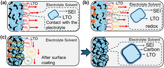 |
| | Fig. 1 Schematic of the LTO electrode during electrochemical cycling. (a) Contact with the electrolyte. (b) Gas generation by LTO during redox reactions. (c) Suppression of gas generation after surface coating with LTO. | |
Based on previous studies, the commonly used coating materials for LTO include carbon, Al2O3, and TiO2, all of which require distinct deposition techniques. Carbon and TiO2 coatings can be applied via conventional pyrolysis; however, as reported by Lv et al.,32 this method often leads to non-uniform coatings and particle agglomeration. However, Al2O3 is typically deposited using ALD,33,34 which ensures excellent uniformity but is costly and difficult to scale for mass production. Although Al2O3 and TiO2 coatings are effective in stabilizing the SEI by suppressing side reactions, their high cost and complex processing steps limit their feasibility for commercial applications. Carbon coatings, in contrast, provide a more cost-effective and scalable alternative while enhancing electrical conductivity and mitigating gas evolution. Various techniques are available for applying carbon coatings, with pyrolysis, ball milling, and spray granulation being the most commonly used methods. Pyrolysis is generally considered the most cost-effective approach; however, the method can be hampered by uneven carbon thickness and particle agglomeration.35 Ball milling, when not requiring high temperatures for coating, can suffer from poor dispersion affecting carbon layer uniformity.36 Spray granulation offers several advantages for large-scale production. This method enhances carbon layer uniformity, improves particle dispersion, and provides greater scalability, making it a more suitable choice for industrial applications. In this study, we chose carbon as the coating material owing to its availability and low cost, and previous studies have shown that carbon coatings can effectively suppress gas generation and significantly enhance cycling life.37,38 However, the reported synthesis processes are often complex and time-consuming, limiting their feasibility for large-scale industrial manufacturing and practical applications. To address this issue, we utilized a large-scale rapid spray granulation technique to form a protective carbon layer on the LTO surface.39–47 This coating is found to improve conductivity and reduce interfacial gas production. Electrochemical analysis techniques were employed to investigate interfacial electrochemical changes and determine the optimal conditions for minimizing gas generation.
Experimental section
Synthesis of LTO@C
First, pre-sintered spinel-type LTO (from Xingxin Chemical, Japan) was evenly dispersed in pure DI water, referred to as solution ‘A’. Sucrose was then dissolved and dispersed in DI water at weight percentages of 5%, 7.5%, and 10%, referred to as solution ‘B’. Subsequently, solutions A and B were thoroughly mixed and continuously fed into a spray dryer (CNK SDDNH-3, GUS Technology Co., Ltd, Taipei, Taiwan) using a peristaltic pump. Gas was used to atomize the mixture through a nozzle into a preheated tubular furnace for drying. During the spray drying process, a gas pressure of 0.2 MPa is maintained as it enters the tubular furnace at a temperature of 200 °C. As the sprayed droplets undergo rapid drying, capillary contraction encapsulates sucrose onto the surface of the LTO. The product collected in a collection bin through the cyclone separator-driven flow constitutes the precursor material. The obtained products were then sent into a box furnace under a nitrogen atmosphere and calcined at 600 °C for 5 h, transforming into LTO@C composite material. Note that the pristine sample and the sucrose-added powders were named LC0, LC5, LC7.5, and LC10.
Material characterization
The crystal structure was characterized using X-ray diffraction (XRD, Empyrean) with a Cu Kα radiation source ranging from 10° to 90° in 2θ. Raman spectroscopy (Horiba, iHR550) was employed to detect the LTO@C composite material. The surface elemental characteristics of the LTO@C samples before and after cycling were analyzed using high-energy X-ray photoelectron spectroscopy (XPS, ULVAC-PHI (Quantes)). Field Emission Scanning Electron Microscopy (FE-SEM, FEI Inspect-F SEM) and high-resolution transmission electron microscope (HR-TEM, JEOL) operated at 200 kV were used to examine the morphology and microstructure of the carbon-coated LTO@C samples.
Electrochemical measurements
Electrochemical measurements were performed using CR2032 button cells, with each half-cell assembly consisting of a 13 mm diameter working electrode, a 15 mm diameter lithium metal anode serving as both the counter and reference electrodes, and a polypropylene separator from Asashi. The working electrode was prepared by creating a uniform slurry from 91 wt% active material, 5 wt% PVDF binder, and 4 wt% super P in N-methyl pyrrolidone (NMP) through continuous stirring for one hour. This slurry was then cast onto aluminum foil and dried at 110 °C overnight. Before assembly, the working electrode was pre-wetted with a standard electrolyte solution, which consisted of a 1 M LiPF6 solution mixed with ethylene carbonate (EC) and dimethyl carbonate (DEC) in a 1![[thin space (1/6-em)]](https://www.rsc.org/images/entities/char_2009.gif) :1 weight ratio, both purchased from Formosa Co., Taiwan. All cells were assembled in an argon-filled glove box (Vigor).
:1 weight ratio, both purchased from Formosa Co., Taiwan. All cells were assembled in an argon-filled glove box (Vigor).
The galvanostatic charge–discharge process was performed between 1 and 3 V (vs. Li/Li+) at a current rate of 0.1C (1C = 170 mAh g−1) with a ThinkLab cycler (TPT-B1HCL010A, Think Power Technology Co., Ltd, Taipei, Taiwan). Cyclic voltammetry was performed in a potential window ranging from 1 to 2 V at a scan rate of 0.1 mV s−1 using a PARSTAT MC 200 electrochemical workstation at room temperature. Electrochemical impedance spectroscopy was performed using the same workstation with an AC amplitude of 10 mV between 200 kHz and 0.1 Hz.
Results and discussion
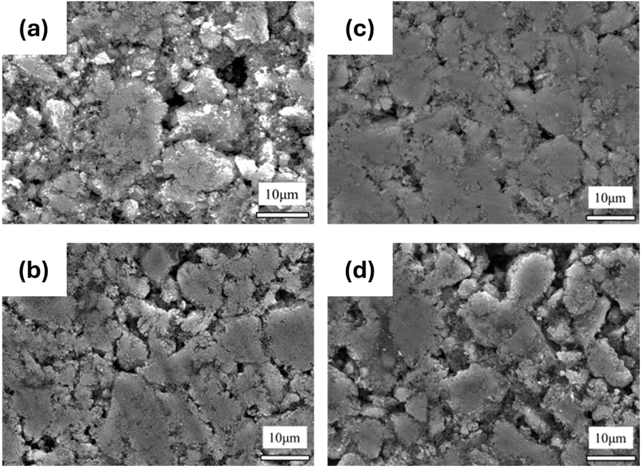
Fig. 2(a)–(d) shows the XRD patterns and Rietveld refinement data of samples LC0, LC5, LC7.5, and LC10. The refinement results for LTO in Table S1† (spinel structure, space group Fd![[3 with combining macron]](https://www.rsc.org/images/entities/char_0033_0304.gif) m, ICSD Pattern 98-003-5273) demonstrate a consistent LTO single phase for all samples. The a-axis of all samples was ∼8.358 Å, as displayed in Table S1,† which is consistent with the reported results.48–50 Furthermore, no carbon signals were observed in the XRD patterns of LC5, LC7.5, and LC10, indicating that the carbon coating was amorphous and did not affect the LTO matrix. To deeply investigate the structural changes induced by the carbon coating on LTO, Raman spectroscopy measurements were performed on the materials, as shown in Fig. 3. The results for all samples revealed characteristic peaks of F2g at 230, 262, and 350 cm−1, along with peaks of Eg and A1g at 425 and 671 cm−1, respectively.51–53 The lower frequency F2g peak corresponds to the bending vibration of the O–Ti–O bond. The Eg peak, observed at an intermediate frequency, is associated with the stretching vibration of the Li–O bond within the LiO4 polyhedron. The higher frequency A1g Raman peak refers to the tensile vibration of the Ti–O bond in the TiO6 octahedron. As shown in Fig. 3(a), these peaks in LTO@C samples are noticeably weaker and broader than in LTO, indicating a potential enhancement in electronic conductivity in the former.54 According to the findings of Zhang et al.,55 enhanced electronic conductivity can reduce the skin depth of incident photons, which in turn affects the intensity of the Raman spectra, reflecting this phenomenon. However, the characteristic peaks around 1300 and 1600 cm−1 shown in Fig. 3(b)–(e), corresponding to the carbon D-band (disordered carbon) and G-band (graphitic carbon), respectively, confirm the presence of the carbon coating on LTO. The intensity ratio of the D to G bands (ID/IG) can be utilized to estimate the degree of graphitization. The highest ID/IG ratio of 0.8 is found in the LC5 sample, suggesting that the LC5 sample exhibits better electrical conductivity.56–58 Additionally, measurements from a laser particle size analyzer revealed that increasing the carbon content led to an increase in the particle size, as detailed in Table S2.† Notably, sample LC5 had a D90 of 12.93 μm, which was smaller than those of the non-coated and other coated samples. This reduction in particle size not only contributes to enhanced ion transport59,60 but also makes the electrode surface smooth and dense, as observed in the SEM images shown in Fig. 4(a)–(b). Furthermore, Table S2† presents the surface charge of all samples, revealing a clear shift to negative values after carbon coating. This negative surface charge facilitates interactions with positively charged particles or molecules, which, in turn, enhances Li-ion transport.61,62
m, ICSD Pattern 98-003-5273) demonstrate a consistent LTO single phase for all samples. The a-axis of all samples was ∼8.358 Å, as displayed in Table S1,† which is consistent with the reported results.48–50 Furthermore, no carbon signals were observed in the XRD patterns of LC5, LC7.5, and LC10, indicating that the carbon coating was amorphous and did not affect the LTO matrix. To deeply investigate the structural changes induced by the carbon coating on LTO, Raman spectroscopy measurements were performed on the materials, as shown in Fig. 3. The results for all samples revealed characteristic peaks of F2g at 230, 262, and 350 cm−1, along with peaks of Eg and A1g at 425 and 671 cm−1, respectively.51–53 The lower frequency F2g peak corresponds to the bending vibration of the O–Ti–O bond. The Eg peak, observed at an intermediate frequency, is associated with the stretching vibration of the Li–O bond within the LiO4 polyhedron. The higher frequency A1g Raman peak refers to the tensile vibration of the Ti–O bond in the TiO6 octahedron. As shown in Fig. 3(a), these peaks in LTO@C samples are noticeably weaker and broader than in LTO, indicating a potential enhancement in electronic conductivity in the former.54 According to the findings of Zhang et al.,55 enhanced electronic conductivity can reduce the skin depth of incident photons, which in turn affects the intensity of the Raman spectra, reflecting this phenomenon. However, the characteristic peaks around 1300 and 1600 cm−1 shown in Fig. 3(b)–(e), corresponding to the carbon D-band (disordered carbon) and G-band (graphitic carbon), respectively, confirm the presence of the carbon coating on LTO. The intensity ratio of the D to G bands (ID/IG) can be utilized to estimate the degree of graphitization. The highest ID/IG ratio of 0.8 is found in the LC5 sample, suggesting that the LC5 sample exhibits better electrical conductivity.56–58 Additionally, measurements from a laser particle size analyzer revealed that increasing the carbon content led to an increase in the particle size, as detailed in Table S2.† Notably, sample LC5 had a D90 of 12.93 μm, which was smaller than those of the non-coated and other coated samples. This reduction in particle size not only contributes to enhanced ion transport59,60 but also makes the electrode surface smooth and dense, as observed in the SEM images shown in Fig. 4(a)–(b). Furthermore, Table S2† presents the surface charge of all samples, revealing a clear shift to negative values after carbon coating. This negative surface charge facilitates interactions with positively charged particles or molecules, which, in turn, enhances Li-ion transport.61,62
 |
| | Fig. 2 XRD patterns and Rietveld refinements for samples (a) LC0, (b) LC5, (c) LC7.5, and (d) LC10. | |
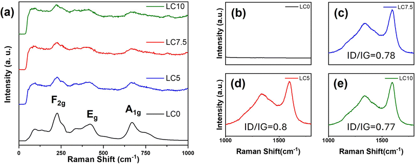 |
| | Fig. 3 (a) Raman spectra of LC0, LC5, LC7.5, and LC10, covering the 0–1000 cm−1 range. (b–d) Zoomed-in view of the 1000–1800 cm−1 region, showing the D-band and G-band characteristics of all samples. | |
 |
| | Fig. 4 Top-view SEM images for samples (a) LC0, (b) LC5, (c) LC7.5, and (d) LC10. | |
To further investigate the microstructure and elemental composition of LC0 and LC5, HR-TEM and EDX mappings were employed, as shown in Fig. 5(a)–(d). Lattice fringes of 0.25 nm, corresponding to the (311) crystal plane of the LTO spinel phase, are observed in Fig. 5(c). In contrast, the HR-TEM images of LC5 revealed two different lattice fringes of 0.478 and 0.251 nm, corresponding to the (111) and (311) planes of the LTO, respectively, as shown in Fig. 5(d). Moreover, the thickness of the amorphous carbon layer is estimated to be ∼2–3 nm. This indicates that the spray granulation process can effectively and uniformly coat the LTO surface with a carbon layer, preventing a direct reaction between the internal LTO and the electrolyte, thus reducing gas production. Additionally, the elemental mappings presented in Fig. 5(e)–(h) show that the distribution area of carbon (red dots) coincides with oxygen (cyan-blue dots) and titanium (green dots), indicating that amorphous carbon uniformly covers the LTO. This further confirms the uniformity of the carbon coating achieved by the spray granulation process.
 |
| | Fig. 5 TEM images of LC0 (a and c) and LC5 (b and d). (e–h) EDX mapping photographs for C, Si, and O in sample LC5. | |
The electrochemical performance shown in Fig. 6 (a) reveals that all carbon-coated LTO samples exhibit superior cycling stability compared to pristine LTO during a 200-cycle test at a 1C charge–discharge rate in a potential range of 1–2 V. Though all carbon-coated LTO samples exhibit excellent capacity retention, voltage degradation was observed during extended cycling, depending on the thickness of the carbon coating (see Fig. S3 in the ESI†). Among these, the LC5 sample exhibited the best stability, highlighting that an excessively thick carbon layer is detrimental. These findings suggest that surface coating significantly influences the chemical properties of the material, thereby impacting its performance. Importantly, our samples achieved enhanced electrochemical performance, representing a substantial improvement over previously reported LTO@C samples, as shown in Fig. 6(b).63–67
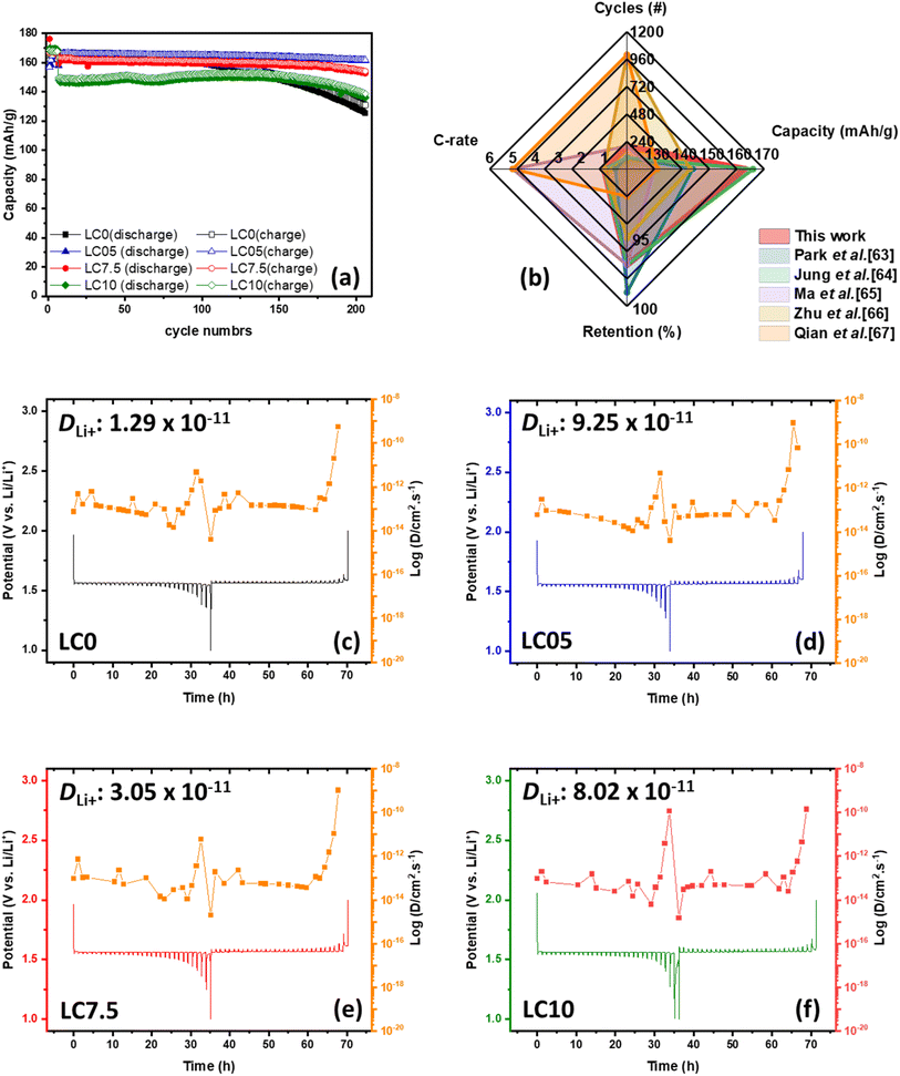 |
| | Fig. 6 (a) Comparative cycling performance of all the samples. (b) Performance comparison of this work and other reported studies. (c–f) GITT profiles were measured at 0.05C for each sample, and the corresponding diffusion coefficients were derived from these profiles. | |
We further used the galvanostatic intermittent titration technique (GITT) to estimate the Li-ion diffusion coefficients of all samples. In the GITT experiments, a 0.05C current pulse was applied for 10 minute, followed by a 10 minute relaxation period in an open-circuit state. We recorded the initial non-equilibrium voltage and the final equilibrium open-circuit voltage and then calculated the Li-ion diffusion coefficient using eqn (1):68,69
| |
 | (1) |
where
DLi+ is the lithium-ion diffusion coefficient;
τ is the constant current pulse time;
mB is the mass of the active material on the electrode;
Vm is the molar volume of the electrode material, which can be calculated from the electrode sheet volume, molecular weight of the active material, and the mass of the active material in the electrode sheet;
MB is the molar mass of the electrode material (459.1448 g mol
−1);
S is the contact area between the electrode and the electrolyte (1.53938 cm
2); Δ
Es is the difference in potential after stabilization; and Δ
Et is the voltage change of the battery during constant current charge and discharge over time
τ. After performing the calculations and plotting the data, as shown in
Fig. 6(c), we found that the average
DLi+ values for LC0, LC5, LC7, and LC10 were 1.29 × 10
−11, 9.25 × 10
−11, 3.05 × 10
−11, and 8.02 × 10
−12 cm
2 s
−1, respectively. The LC5 electrode exhibited the highest values, indicating a significant enhancement in Li-ion intercalation and deintercalation. Additionally, calculations of the lithium-ion diffusion coefficient revealed that a thicker carbon layer results in lower ion diffusion efficiency. These findings suggest that excessive carbon coating hinders charge transport
via two primary mechanisms. First, the increased carbon thickness elevates the internal resistance likely owing to the reduced electronic conductivity of thicker carbon coatings compared to the LTO substrate.
70,71 Second, a thicker carbon layer impedes lithium-ion transport by creating a longer and less conductive pathway, thereby reducing the diffusion kinetics.
72 Moreover, an excessively thick carbon coating may alter solid electrolyte interphase (SEI) formation, potentially introducing additional interfacial resistance.
The stability of the LTO/electrolyte interface is a key factor influencing LTO battery performance. In the early stages of SEI formation, the decomposition of LTO and electrolyte molecules generates CO2, Li2CO3, and Li2O. The interaction between Li2CO3 and LTO facilitates the formation of over-lithiated phases, such as Li2O and lithium carbides (LiCx), on the LTO surface. This continuous SEI growth accelerates capacity degradation and shortens the cycle life. To understand these effects, XPS analysis was conducted on all samples both before and after 200 cycles, as shown in Fig. S2† and 7. Compared with the XPS spectrum of Ti 2p of all samples before cycling, a small negative shift can be observed in the XPS spectrum following carbon coating, indicating the Ti(III) modification on the outer surface. As reported by Colbow et al.,73 surface Ti3+ significantly enhances the electronic conductivity of carbon-coated LTO. Unlike Ti4+, Ti3+ possesses an electron in the Ti:t2 band, contributing to improved conductivity. This conclusion is further supported by thermogravimetric analysis (TGA) in Fig. S4(a),† where a slight weight increase in carbon-coated LTO between 120 °C and 300 °C is likely due to the oxidation of Ti3+,74 confirming its presence in the as-prepared material. It should be mentioned that oxygen vacancies are known to reduce the band gap of bulk LTO, thereby improving conductivity and electrochemical performance. However, our O 1s spectra (Fig. S2(e–h)†) did not show the characteristic oxygen vacancy peak. This suggests that oxygen vacancies are unlikely to contribute to the improvement of the conductivity in our system, which is consistent with the band gap values of 3.88, 3.87, 3.88 and 3.89 eV from our Tauc plots (Fig. S4(b)†) for samples LC0, LC5, LC7.5 and LC10, respectively. However, the Ti 2p spectra for all electrodes showed no detectable Ti signals after 200 cycles, suggesting that a thick SEI layer was formed on the surface after long-term cycling. This result is consistent with observations reported by Ma et al.75 However, interesting differences were observed in the C 1s, O 1s, and F 1s spectra, as shown in Fig. 7(a–h) and (m–p). The C 1s spectra reveal that the SEI is composed of signals at 286.2 (C–O), 286.6 (ROLi), 288.7 (C![[double bond, length as m-dash]](https://www.rsc.org/images/entities/char_e001.gif) O), and 290.1 (ROCO2Li, Li2CO3) eV. The O 1s spectra show signals at 528.5 (Li2O), 530.4 (ROLi), 531.4 (CO3), and 290.1 (C–O) eV. Additionally, the F 1s spectra exhibit signals at 685 (LiF) and 687.2 (CF2) eV, consistent with previous findings from other groups.75–78 The analysis indicates that the SEI is mainly composed of Li2CO3 and Li2O. From the C 1s and O 1s spectra, Li2O was the primary component in the SEI of pristine LTO, with only trace amounts of Li2CO3. Previous studies have shown that Li2CO3 in the SEI continuously reacts with the electrolyte, degrading cycling performance.79,80 In uncoated LTO, this reaction consumes Li2CO3, resulting in a weak signal. Thus, the carbon coating serves as a protective barrier, minimizing direct contact between the LTO and the electrolyte. This allows both Li2CO3 and Li2O to contribute to SEI stabilization, thereby enhancing cycling stability. Furthermore, the results suggest that without a carbon coating, a stable Li2CO3 layer cannot be maintained to support a robust SEI. Consequently, the unstable Li2CO3 layer continues to react with LTO, leading to the formation of Li2O and CO2 on the LTO surface, which subsequently contributes to gas generation. However, as the carbon content increases, the signal weakens, suggesting that excessive carbon may accelerate SEI formation and electrolyte consumption. Therefore, a moderate carbon coating is the most effective for SEI stabilization.
O), and 290.1 (ROCO2Li, Li2CO3) eV. The O 1s spectra show signals at 528.5 (Li2O), 530.4 (ROLi), 531.4 (CO3), and 290.1 (C–O) eV. Additionally, the F 1s spectra exhibit signals at 685 (LiF) and 687.2 (CF2) eV, consistent with previous findings from other groups.75–78 The analysis indicates that the SEI is mainly composed of Li2CO3 and Li2O. From the C 1s and O 1s spectra, Li2O was the primary component in the SEI of pristine LTO, with only trace amounts of Li2CO3. Previous studies have shown that Li2CO3 in the SEI continuously reacts with the electrolyte, degrading cycling performance.79,80 In uncoated LTO, this reaction consumes Li2CO3, resulting in a weak signal. Thus, the carbon coating serves as a protective barrier, minimizing direct contact between the LTO and the electrolyte. This allows both Li2CO3 and Li2O to contribute to SEI stabilization, thereby enhancing cycling stability. Furthermore, the results suggest that without a carbon coating, a stable Li2CO3 layer cannot be maintained to support a robust SEI. Consequently, the unstable Li2CO3 layer continues to react with LTO, leading to the formation of Li2O and CO2 on the LTO surface, which subsequently contributes to gas generation. However, as the carbon content increases, the signal weakens, suggesting that excessive carbon may accelerate SEI formation and electrolyte consumption. Therefore, a moderate carbon coating is the most effective for SEI stabilization.
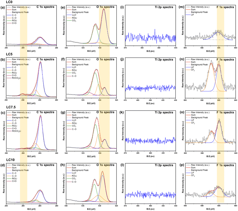 |
| | Fig. 7 XPS spectra of all samples, showing (a–d) C 1s, (e–h) O 1s, (i–l) Ti 2p, and (m–p) F 1s regions after 200 cycles. | |
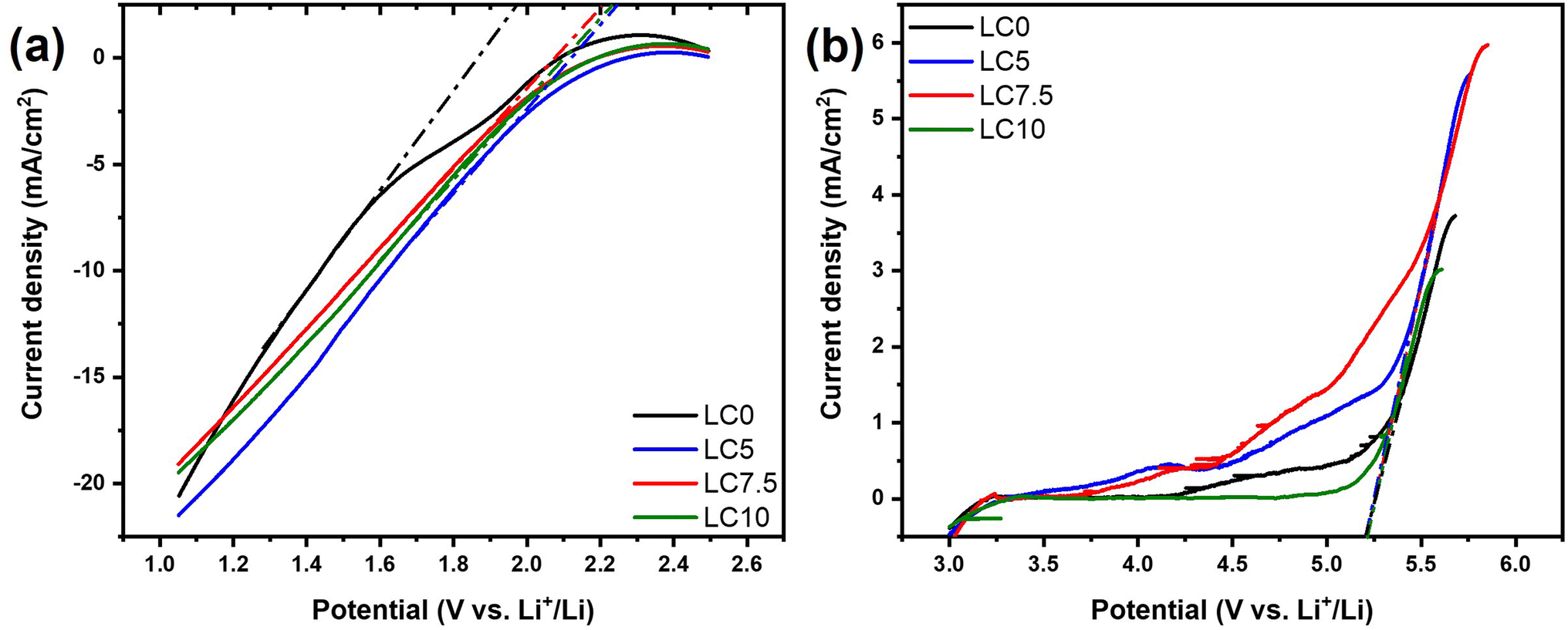
Thus far, the electrochemical performance of LTO has been understood to be highly dependent on the stability of the LTO/electrolyte interface, which can be quantitatively assessed through SEI formation kinetics. Consequently, it is important to investigate the interactions between the carbon coating layer and LTO within the electrode. As suggested by Yi et al.,23 the gas release of LTO in aqueous electrolytes is easily observable, with voltages during catalysis tests converted to Li+/Li potentials. To further evaluate the interfacial reactions in all samples, linear sweeping voltammetry (LSV) was conducted in a three-electrode electrochemical cell at room temperature. A graphite rod served as the counter electrode for the hydrogen evolution reaction (HER) tests, and Pt foil (1 cm2) was used for the oxygen evolution reaction (OER) tests. An Ag/AgCl/KCl (3 M) electrode was chosen as the reference electrode. All recorded voltages were carried out in 0.1 M Na2SO4 aqueous electrolyte (pH = 7) at a sweep rate of 5 mV s−1 and converted against the redox potential of lithium using the relationship VLi+/Li = 3.045 V + Vx + 0.197 V + 0.059 pH, where VLi is the voltage vs. Li+/Li and Vx is the voltage measured during catalytic experiments. During the HER, as shown in Fig. 8, the LC5 electrode exhibited the highest overpotential of around 2.25 V vs. Li+/Li. This value is slightly higher than the overpotential of ∼1.98 V observed for pristine LTO, indicating a weaker catalytic capability for the LC5 electrode. However, Fig. 8 demonstrates that oxygen evolution for all samples initiates only at an overpotential exceeding 5.18 V vs. Li+/Li according to the OER findings. This potential is significantly beyond the typical operational range (0.8 to 3 V vs. Li+/Li) of LTO in battery applications. Therefore, the OER is unlikely to occur during normal battery operation. The HER/OER tests demonstrate that the carbon coating layers alter the surface characteristics of the LTO electrode, effectively regulating its surface activity and possibly leading to less gas production during cell operation.
 |
| | Fig. 8 Catalytic performances of LC0, LC5, LC7.5, and LC10. (a) HER and (b) OER polarization curves measured in 0.1 M Na2SO4 aqueous solution for different samples. All measured voltages were converted to values vs. Li+/Li. | |
To further investigate the surface activities of LC0, LC5, LC7, and LC10 at the electrolyte interface, a distribution of relaxation time (DRT) analysis was carried out. This analysis was used to assess the impedance responses of all the samples recorded at various voltages during Li-ion intercalation and deintercalation at the electrode interface. The results, combined with electrochemical impedance spectroscopy (EIS), generated a 2D color map, providing a detailed examination of interfacial changes. As shown in Fig. 9, different frequency phenomena are represented: P1 corresponds to the surface film resistance, P2 represents the charge transfer resistance at the electrode/electrolyte interface, and P3 indicates the solid-state diffusion of the active material.81–83 In the 2D color maps for LC0 during charge and discharge (Fig. 9(a)), there are no signs of increased resistance at P1 or P2 during lithium-ion intercalation. However, during lithium-ion deintercalation at 1.6 V (Fig. 9(e)), there is an increase in resistance at P1, which is attributed to SEI formation on the surface. For LC5, LC7, and LC10 (Fig. 9(b)–(d)), after carbon coating, increased resistance signals were observed at both P1 and P2 during lithium-ion intercalation. Specifically, at 1.4 V, a notable increase in surface film resistance (P1) and a rise in the charge transfer resistance (P2) at 1.5 V were observed. During lithium-ion deintercalation (Fig. 9(f)–(h)), a stronger resistance signal at P1 between 1.6 and 1.5 V was observed compared to uncoated LTO. Additionally, P2 showed increased resistance at 1.8 V, emphasizing the impact of carbon coating on interfacial properties. This suggests that the carbon coating affected the resistance signals during the lithium-ion insertion process. The results of the charge and discharge analyses indicate that the increased resistance response signals for P1 and P2 are likely due to the protective amorphous carbon layer on the surface of the LTO@C material. Similar findings were reported in our previous studies.84–86 Furthermore, the XPS data from the 200-cycle experiment shown in Fig. 7 suggest that the carbon layer on LTO@C stabilized the formation of the SEI layer, whereas the SEI formed on non-coated LTO was less stable. Consequently, the surface film resistance and charge transfer resistance at the electrode/electrolyte interface during Li-ion intercalation and deintercalation did not exhibit significant changes in resistance for the non-coated LTO. Based on the XPS and DRT results, it is evident that the carbon coating on LTO regulated its surface activity and facilitated the formation of a stable SEI layer. A stable SEI layer is beneficial for Li-ion diffusion.87,88
 |
| | Fig. 9 Color-mapped DRT plots showing Li transition paths for the LC0, LC5, LC7.5, and LC10 electrodes during (a–d) lithiation and (e–h) delithiation. | |
Conclusion
In summary, the above analysis provides insights into how the spray granulation coating of a carbon layer affects the material properties and surface morphology of LTO, as well as the electrochemical behavior at the interface between the electrode and the electrolyte. Spray granulation allows for the rapid coating of the material with a carbon layer. The XRD results indicate that this process does not affect the material structure, as the spinel structure of LTO is maintained after granulation, and Raman spectroscopy clearly shows signals for both LTO and amorphous carbon. SEM analysis reveals that with a 5% sucrose weight percentage coating, LTO@C achieves a uniform surface coating, and TEM confirms that the carbon is uniformly coated on the outer layer of LTO with a thickness of 2–3 nm. After these modifications, the LTO@C electrode was tested over 200 battery cycles. The XPS data show that the LTO@C sample forms a stable SEI layer made up of Li2CO3 and Li2O. This stable SEI layer prevented the loose SEI on the LTO surface from reacting directly with the electrolyte to produce gas, indicating that the coating effectively suppressed gas production. Further analysis showed that the carbon coating formed a stable SEI, affecting the impedance response in the DRT analysis. The LTO@C sample exhibited increased resistance owing to the carbon layer and SEI on the surface. The lithium-ion diffusion coefficient, estimated using the GITT, is higher for LTO@C with 5% sucrose (9.25 × 10⁻¹¹ cm2 s−1), demonstrating significant improvement in the electrochemical performance of the LTO@C electrode. After 200 cycles at 1C, the LTO@C with 5% sucrose maintained a capacity of 161 mAh g−1 with a 97% capacity retention rate. Moreover, during the measurement of the HER using LSV, the LTO@C electrode with 5% sucrose shows a slightly higher overpotential of approximately 2.25 V vs. Li+/Li, indicating its ability to effectively suppress gas generation. These findings demonstrate that spray granulation is a rapid and efficient technique for uniformly coating LTO surfaces with a carbon layer. This modification results in a stable SEI layer on the electrode surface, which improves the cycling stability of the battery and effectively addresses the issue of gas production.
Data availability
The data supporting the findings of this article have been included as part of the ESI.†
Author contributions
P. M. Wu, Y. C. Chiu, P. W. Chi, and M. K. Wu conceptualized the study, designed the framework, and conducted the final review of this document. D. Z. Wu, W. C. Hsu, and H. E. Lin carried out the experiments. Data analysis was performed by D. Z. Wu, C. H. Chung, H. Y. Hsieh, W. M. Chen, F. Y. Wu, and Y. H. Su. D. Z. Wu, Y. C. Chiu, P. W. Chi, P. M. Wu, and M. K. Wu collaborated on drafting the manuscript and preparing the figures. P. M. Wu, Y. C. Chiu, and P. W. Chi coordinated the teamwork. All authors thoroughly reviewed and revised the manuscript.
Conflicts of interest
The authors have no conflicts of interest to declare.
Acknowledgements
The authors greatly appreciate the financial support from the Executive Yuan via its Forward-Looking Research Grant Number AS-FLI-110-LI and the Ministry of Education of Taiwan (the Sustainable Electrochemical Energy Development Center (SEED Center)). Additional support was provided by the National Science and Technology Council of Taiwan (NSTC 113-2112-M-001-046). Phillip M. Wu further acknowledges the support from the “Innovative Center on Sustainable Negative-Carbon Resources” from the Featured Areas Research Center Program within the framework of the Higher Education Sprout Project by the Ministry of Education (MOE) in Taiwan.
References
- I. Hannula, et al., Near-Term Potential of Biofuels, Electrofuels, and Battery Electric Vehicles in Decarbonizing Road Transport, Joule, 2019, 3, 2390–2402 CrossRef CAS.
- M. Wolinetz, et al., Simulating the Value of Electric-Vehicle–Grid Integration Using a Behaviourally Realistic Model, Nat. Energy, 2018, 3, 132–139 CrossRef.
- H. Rezaei, et al., Energy Management Strategies of Battery-Ultracapacitor Hybrid Storage Systems for Electric Vehicles: Review, Challenges, and Future Trends, J. Energy Storage, 2022, 53, 105045 CrossRef.
- M. Ko, et al., Scalable Synthesis of Silicon-Nanolayer-Embedded Graphite for High-Energy Lithium-Ion Batteries, Nat. Energy, 2016, 1, 16113 CrossRef CAS.
- Y. Cao, et al., Multi-Scale Swelling Behaviors and Mechanisms of Graphite Electrode-Based Lithium-Ion Battery at Various Charging Rates, J. Power Sources, 2024, 606, 234504 CrossRef CAS.
- C. M. Julien, et al., Fabrication of Li4Ti5O12 (LTO) as Anode Material for Li-Ion Batteries, Micromachines, 2024, 15(3), 310 CrossRef PubMed.
- H. Zhang, et al., Li4Ti5O12 Spinel Anode: Fundamentals and Advances in Rechargeable Batteries, InfoMat, 2022, 4(4), e12228 CrossRef CAS.
- M. Thackeray, et al., Li4Ti5O12 Spinel Anodes, Nat. Energy, 2021, 6, 683 CrossRef CAS.
- J. Wang, et al., Enhancing the Kinetic Lithium Insertion in Li4Ti5O12 by Introducing Anatase TiO2, J. Electroanal. Chem., 2024, 957, 118107 CrossRef CAS.
- G. Zhu, et al., Nano/Micrometer Porous Conductive Network Structure Li4Ti5O12@C/CNT Microspheres with Enhanced Sodium-Storage Capability as an Anode Material, RSC Adv., 2022, 12(41), 26782–26788 RSC.
- Y. Jiang, et al., Hierarchical Li4Ti5O12/TiO2 Composite Tubes with Regular Structural Imperfection for Lithium Ion Storage, Sci. Rep., 2013, 3, 3490 CrossRef PubMed.
- Z. Yang, et al., Highly Reversible Lithium Storage in Uniform Li4Ti5O12/Carbon Hybrid Nanowebs as Anode Material for Lithium-Ion Batteries, Energy, 2013, 55, 925–932 CrossRef CAS.
- Y. Hu, et al., Carbon-Coated Li4Ti5O12 Nanoflakes for Ultra-Fast Charging of Lithium-Ion Batteries, Appl. Surf. Sci., 2024, 656, 159619 CrossRef CAS.
- L. Wang, et al., Synthesis and Assessment of the Electrochemical Performance of Micro-Nano-Spherical Li4Ti5O12-LiAlO2 Composites, J. Alloys Compd., 2023, 966, 171574 CrossRef CAS.
- J. Han, et al., Li4Ti5O12 Composited with Li2ZrO3 Revealing Simultaneously Meliorated Ionic and Electronic Conductivities as High Performance Anode Materials for Li-Ion Batteries, J. Power Sources, 2017, 354, 16–25 CrossRef CAS.
- H. Luo, et al., Carbon Coated Li4Ti5O12 Nanorods as Superior Anode Material for High Rate Lithium Ion Batteries, J. Alloys Compd., 2013, 572, 37–42 CrossRef CAS.
- E. Nezamzadeh, et al., Review on Doping Strategy in Li4Ti5O12 as an Anode Material for Lithium-Ion Batteries, Ceram. Int., 2023, 49(5), 7105–7141 CrossRef.
- P. Tsai, et al., Ab Initio Phase Stability and Electronic Conductivity of the Doped-Li4Ti5O12 Anode for Li-Ion Batteries, Acta Mater., 2019, 175, 196–205 CrossRef CAS.
- N. Gauthier, et al., Impact of the Cycling Temperature on Electrode/Electrolyte Interfaces within Li4Ti5O12 vs LiMn2O4 Cells, J. Power Sources, 2020, 448, 227573 CrossRef CAS.
- C. Han, et al., A Review of Gassing Behavior in Li4Ti5O12-Based Lithium Ion Batteries, J. Mater. Chem. A, 2017, 5, 6368–6381 RSC.
- K. Xu, Nonaqueous Liquid Electrolytes for Lithium-Based Rechargeable Batteries, Chem. Rev., 2004, 104(10), 4303–4418 CrossRef CAS PubMed.
- M. D. S. Lekgoathi, et al., Decomposition Kinetics of Anhydrous and Moisture Exposed LiPF6 Salts by Thermogravimetry, J. Fluorine Chem., 2013, 149, 53–56 CrossRef CAS.
- H. Yi, et al., Synergetic Charge Transfer from Ti–O2-Basic Centers at Li4Ti5O12 Spinel Surface, Solid State Ionics, 2022, 375, 115852 CrossRef CAS.
- Y. He, et al., Gassing in Li4Ti5O12-Based Batteries and Its Remedy, Sci. Rep., 2012, 2, 913 CrossRef PubMed.
- J. Hoffmann, et al., Investigation of Gas Evolution from Li4Ti5O12 Anode for Lithium Ion Batteries, J. Electrochem. Soc., 2018, 165(13), A3108–A3113 CrossRef CAS.
- I. Belharouak, et al., Performance Degradation and
Gassing of Li4Ti5O12/LiMn2O4 Lithium-Ion Cells, J. Electrochem. Soc., 2012, 159(8), A1165–A1170 CrossRef CAS.
- J. Zhang, et al., Assembly of Multifunctional Li4Ti5O12@Co3O4 Heterostructures for High-Performance Li-Ion Half/Full Batteries, J. Alloys Compd., 2021, 856, 158110 CrossRef CAS.
- W. Li, et al., The Role of ‘ZrF4-Modification’ on the Structure and Electrochemical Performance of Li4Ti5O12 Anode Material, J. Alloys Compd., 2018, 745, 659–668 CrossRef CAS.
- Y. Wang, et al., Investigation into the Surface Chemistry of Li4Ti5O12 Nanoparticles for Lithium Ion Batteries, ACS Appl. Mater. Interfaces, 2016, 8(39), 26008–26012 CrossRef CAS PubMed.
- W. Li, et al., AlF3 Modification to Suppress the Gas Generation of Li4Ti5O12 Anode Battery, Electrochim. Acta, 2014, 139, 104–110 CrossRef CAS.
- L. Wen, et al., Effect of Formation Potentials on Gassing of LiMn2O4//Li4Ti5O12/C Batteries, J. Electrochem. Soc., 2019, 166(3), A5033–A5037 CrossRef CAS.
- S. Lv, et al., One-step synthesis of a double conductive layer C-SiOx-TiO2 co-coated Li4Ti5O12 anode material toward a high-rate and large-capacity lithium-ion battery, Appl. Surf. Sci., 2021, 555, 149637 CrossRef CAS.
- D. Ahn, et al., Enhanced rate capability of oxide coated lithium titanate within extended voltage ranges, Front. Energy Res., 2015, 3, 21 Search PubMed.
- J. K. Yoo, et al., Highly-Stable Li4Ti5O12 Anodes Obtained by Atomic-Layer-Deposited Al2O3, Materials, 2018, 11, 803 CrossRef PubMed.
- B. Tang, et al., Carbon-coated Li4Ti5O12 tablets derived from metal-organic frameworks as anode material for lithium-ion batteries, J. Alloys Compd., 2017, 708, 6–13 CrossRef CAS.
- Y. R. Jhan, et al., Synthesis of entanglement structure in nanosized Li4Ti5O12/multi-walled carbon nanotubes composite anode material for Li-ion batteries by ball-milling-assisted solid-state reaction, J. Power Sources, 2012, 198, 294–297 CrossRef CAS.
- X. Li, et al., In-Situ Carbon Coating to Enhance the Rate Capability of the Li4Ti5O12 Anode Material and Suppress the Electrolyte Reduction Decomposition on the Electrode, Electrochim. Acta, 2016, 190, 69–75 CrossRef CAS.
- Y. He, et al., Carbon Coating to Suppress the Reduction Decomposition of Electrolyte on the Li4Ti5O12 Electrode, J. Power Sources, 2012, 202, 253–261 CrossRef CAS.
- H. Roh, et al., Polyol-Mediated Carbon-Coated Li4Ti5O12 Nanoparticle/Graphene Composites with Long-Term Cycling Stability for Lithium and Sodium Ion Storages, Chem. Eng. J., 2020, 385, 123984 CrossRef.
- J. Liu, et al., Spherical Li4Ti5O12/NiO Composite with Enhanced Capacity and Rate Performance as Anode Material for Lithium-Ion Batteries, Front. Chem., 2020, 8, 626388 CrossRef CAS PubMed.
- C. Chang-Jian, et al., Spray-Drying Synthesis of Li4Ti5O12 Microspheres in Pilot Scale Using TiO2 Nanosheets as Starting Materials and Their Application in High-Rate Lithium Ion Battery, J. Alloys Compd., 2019, 773, 376–386 CrossRef CAS.
- G. Park, et al., Mesoporous Graphitic Carbon-TiO2 Composite Microspheres Produced by a Pilot-Scale Spray-Drying Process as an Efficient Sulfur Host Material for Li-S Batteries, Chem. Eng. J., 2018, 335, 600–611 CrossRef CAS.
- J. Park, et al., Spray-Drying Assisted Synthesis of a Li4Ti5O12/C Composite for High Rate Performance Lithium Ion Batteries, Ceram. Int., 2018, 44, 2683–2690 CrossRef CAS.
- G. Xu, et al., Facile Spray Drying Route for Large Scale Nitrogen-Doped Carbon-Coated Li4Ti5O12 Anode Material in Lithium-Ion Batteries, Solid State Ionics, 2017, 304, 40–45 CrossRef CAS.
- L. Wen, et al., Dual Functions of Carbon in Li4Ti5O12/C Microspheres, J. Electrochem. Soc., 2015, 162(2), A3038–A3044 CrossRef CAS.
- S. Han, et al., Solid-State Synthesis of Li4Ti5O12 for High Power Lithium Ion Battery Application, J. Alloys Compd., 2013, 570, 144–149 CrossRef CAS.
- H. Jung, et al., Micron-Sized, Carbon-Coated Li4Ti5O12 as High Power Anode Material for Advanced Lithium Batteries, J. Power Sources, 2011, 196, 7763–7766 CrossRef CAS.
- X. Guo, et al., Morphologies and Structures of Carbon Coated on Li4Ti5O12 and Their Effects on Lithium Storage Performance, Electrochim. Acta, 2014, 130, 470–476 CrossRef CAS.
- Y. He, et al., Carbon Coating to Suppress the Reduction Decomposition of Electrolyte on the Li4Ti5O12 Electrode, J. Power Sources, 2012, 202, 253–261 CrossRef CAS.
- G. J. Wang, et al., Preparation and Characteristic of Carbon-Coated Li4Ti5O12 Anode Material, J. Power Sources, 2007, 174, 1109–1112 CrossRef CAS.
- Z. Zhu, et al., Investigation of Effects of Carbon Coating on the Electrochemical Performance of Li4Ti5O12/C Nanocomposites, J. Mater. Chem. A, 2013, 1, 9484–9490 RSC.
- C. Kim, et al., Mechanism of Phase Propagation During Lithiation in Carbon-Free Li4Ti5O12 Battery Electrodes, Adv. Funct. Mater., 2013, 23, 1214–1222 CrossRef CAS.
- Y. Wang, et al., Solid-State Synthesis of Graphite Carbon-Coated Li4Ti5O12 Anode for Lithium Ion Batteries, Ionics, 2014, 20, 1377–1383 CrossRef CAS.
- Z. Wang, et al., Tuning fermi level and band gap in Li4Ti5O12 by doping and vacancy for ultrafast Li+ insertion/extraction, J. Am. Ceram. Soc., 2021, 104, 5934–5945 CrossRef CAS.
- Y. Zhang, et al., Oxygen Vacancies Evoked Blue TiO2(B) Nanobelts with Efficiency Enhancement in Sodium Storage Behaviors, Adv. Funct. Mater., 2017, 27(27), 1700856 CrossRef.
- G. Zhu, et al., A Comprehensive Study of Effects of Carbon Coating on Li4Ti5O12 Anode Material for Lithium-Ion Batteries, J. Electrochem. Soc., 2011, 158(2), A102–A109 CrossRef CAS.
- C. M. Julien, et al., Electrochemistry and Local Structure of Nano-Sized Li4/3Me5/3O4 (Me=Mn, Ti) Spinels, Electrochim. Acta, 2004, 50, 411–416 CrossRef CAS.
- E. Pohjalainen, et al., Effect of Li4Ti5O12 Particle Size on the Performance of Lithium Ion Battery Electrodes at High C-Rates and Low Temperatures, J. Phys. Chem. C, 2015, 119, 2277–2283 CrossRef CAS.
- H. Yao, et al., Size Effects in Lithium Ion Batteries, Chin. Phys. B, 2016, 25(1), 018203 CrossRef.
- M. Michalska, et al., The Effect of MWCNT Modification on Structural and Morphological Properties of Li4Ti5O12, Diam. Relat. Mater., 2021, 113, 108276 CrossRef CAS.
- H. Dai, et al., Stabilizing lithium metal anode by octaphenyl polyoxyethylene-lithium complexation, Nat. Commun., 2020, 11, 643 CrossRef CAS PubMed.
- G. Li, et al., Electrokinetic Phenomena Enhanced Lithium-Ion Transport in Leaky Film for Stable Lithium Metal Anodes, Adv. Energy Mater., 2019, 9, 1900704 CrossRef.
- J. Park, et al., Spray-drying assisted synthesis of a Li4Ti5O12/C composite for high rate performance lithium-ion batteries, Ceram. Int., 2018, 44(3), 2683–2690 CrossRef CAS.
- H. Jung, et al., Micron-sized, carbon-coated Li4Ti5O12 as high power anode material for advanced lithium batteries, J. Power Sources, 2011, 196(18), 7763–7766 CrossRef CAS.
- G. Ma, et al., Carbon-coated Li4Ti5O12 microspheres synthesized through solid-state reaction in a carbon reduction atmosphere for high-rate lithium-ion batteries, J. Solid State Electrochem., 2022, 26(12), 2893–2905 CrossRef CAS.
- G. Zhu, et al., Carbon-coated nano-sized Li4Ti5O12 nanoporous microsphere as anode material for high-rate lithium-ion batteries, Energy Environ. Sci., 2011, 4(10), 4016–4022 RSC.
- D. Qian, et al., Preparation of Li4Ti5O12/C–C with super long high-rate cycle properties using glucose and polyurethane as double carbon sources for lithium-ion batteries, J. Appl. Electrochem., 2019, 49, 341–351 CrossRef CAS.
- K. M. Shaju, et al., Li Ion Kinetic Studies on Spinel Cathodes, Li(M1/6Mn11/6)O4 (M = Mn, Co, CoAl) by GITT and EIS, J. Mater. Chem., 2003, 13, 106–113 RSC.
- W. Weppner, et al., Determination of the Kinetic Parameters of Mixed-Conducting Electrodes and Application to the System Li3Sb, J. Electrochem. Soc., 1977, 124, 1569 CrossRef CAS.
- J. Zhang, et al., Conformal carbon coating on WS2 nanotubes for excellent electrochemical performance of lithium-ion batteries, Nanotechnology, 2018, 30(3), 035401 CrossRef PubMed.
- J. H. Wang, et al., Si@C Core-Shell Nanostructure-Based Anode for Li-Ion Transport, ACS Appl. Nano Mater., 2023, 6(13), 12578–12587 CrossRef CAS.
- M. Abdollahifar, et al., Enabling Long-Cycling Life of Si-on-Graphite Composite Anodes via Fabrication of a Multifunctional Polymeric Artificial Solid–Electrolyte Interphase Protective Layer, ACS Appl. Mater. Interfaces, 2022, 14(34), 38824–38834 CrossRef CAS PubMed.
- K. M. Colbow, et al., Structure and electrochemistry of the spinel oxides LiTi2O4 and Li43Ti53O4, J. Power Sources, 1989, 26, 397–402 CrossRef CAS.
- B. Yan, et al., Novel understanding of carbothermal reduction enhancing
electronic and ionic conductivity of Li4Ti5O12 anode, J. Mater. Chem. A, 2015, 3, 11773–11781 RSC.
- M. Ma, et al., Characterization of Li Diffusion and Solid Electrolyte Interface for Li4Ti5O12 Electrode Cycled with an Organosilicon Additive Electrolyte, J. Electrochem. Soc., 2020, 167, 110549 CrossRef CAS.
- M. Song, et al., Is Li4Ti5O12 a Solid-Electrolyte-Interphase-Free Electrode Material in Li-Ion Batteries? Reactivity between the Li4Ti5O12 Electrode and Electrolyte, J. Mater. Chem. A, 2014, 2, 631 RSC.
- Y. He, et al., Effect of Solid Electrolyte Interface (SEI) Film on Cyclic Performance of Li4Ti5O12 Anodes for Li Ion Batteries, J. Power Sources, 2013, 239, 269–276 CrossRef CAS.
- R. Dedryvère, et al., Characterization of Lithium Alkyl Carbonates by X-Ray Photoelectron Spectroscopy: Experimental and Theoretical Study, J. Phys. Chem. B, 2005, 109, 15868–15875 CrossRef PubMed.
- B. Han, et al., Poor Stability of Li2CO3 in the Solid Electrolyte Interphase of a Lithium-Metal Anode Revealed by Cryo-Electron Microscopy, Adv. Mater., 2021, 33, 2100404 CrossRef CAS PubMed.
- S. K. Heiskanen, et al., Generation and Evolution of the Solid Electrolyte Interphase of Lithium-Ion Batteries, Joule, 2019, 3, 2322–2333 CrossRef CAS.
- Y. Zhao, et al., Investigation of the Distribution of Relaxation Times of a Porous Electrode Using a Physics-Based Impedance Model, J. Power Sources, 2022, 530, 231250 CrossRef CAS.
- P. Iurilli, et al., Detection of Lithium-Ion Cells' Degradation through Deconvolution of Electrochemical Impedance Spectroscopy with Distribution of Relaxation Time, Energy Technol., 2022, 10, 2200547 CrossRef CAS.
- T. Paul, et al., Computation of Distribution of Relaxation Times by Tikhonov Regularization for Li Ion Batteries: Usage of L-Curve Method, Sci. Rep., 2021, 11, 12624 CrossRef CAS PubMed.
- W. M. Chen, et al., Advanced TiO2/Al2O3 Bilayer ALD Coatings for Improved Lithium-Rich Layered Oxide Electrodes, ACS Appl. Mater. Interfaces, 2024, 16, 13029–13040 CrossRef CAS PubMed.
- Y. H. Su, et al., A Green Recyclable Li3VO4-Pectin Electrode Exhibiting Pseudocapacitive Effect as an Advanced Anode for Lithium-Ion Battery, J. Energy Storage, 2023, 72, 108454 CrossRef.
- P. W. Chi, et al., A Study on Ti-Doped Fe3O4 Anode for Li Ion Battery Using Machine Learning, Electrochemical and Distribution Function of Relaxation Times (DFRTs) Analyses, Sci. Rep., 2022, 12, 4851 CrossRef CAS PubMed.
- Q. Zhang, et al., Synergetic Effects of Inorganic Components in Solid Electrolyte Interphase on High Cycle Efficiency of Lithium Ion Batteries, Nano Lett., 2016, 16, 2011–2016 CrossRef CAS PubMed.
- S. Shi, et al., Defect Thermodynamics and Diffusion Mechanisms in Li2CO3 and Implications for the Solid Electrolyte Interphase in Li-Ion Batteries, J. Phys. Chem. C, 2013, 117(17), 8579–8593 CrossRef CAS.
|
| This journal is © The Royal Society of Chemistry 2025 |
Click here to see how this site uses Cookies. View our privacy policy here. 
 Open Access Article
 This Open Access Article is licensed under a Creative Commons Attribution-Non Commercial 3.0 Unported Licence
 *b,
Yu-Cheng Chiu
*b,
Yu-Cheng Chiu