
 Open Access Article
 This Open Access Article is licensed under a Creative Commons Attribution-Non Commercial 3.0 Unported Licence
Development of the all-solid-state flexible supercapacitor membranes via RAFT-mediated grafting and electrospun nanofiber modification of track-etched membranes
Nurgulim A. Aimanovaa,
Alimzhan A. Almanova,
Saeideh Alipoorib,
Murat Barsbay c,
Alisher M. Zhumabayevad,
Dinara T. Nurpeisovaad and
Anastassiya A. Mashentseva*ad
c,
Alisher M. Zhumabayevad,
Dinara T. Nurpeisovaad and
Anastassiya A. Mashentseva*ad
aThe Institute of Nuclear Physics of the Republic of Kazakhstan, 050032 Almaty, Kazakhstan. E-mail: a.mashentseva@inp.kz
bUNAM, Institute of Materials Science and Nanotechnology, Bilkent University, Ankara 06800, Turkey
cDepartment of Chemistry, Hacettepe University, 06800 Ankara, Turkey
dDepartment of Nuclear Physics, New Materials and Technologies, L. N. Gumilyov Eurasian National University, 010008 Astana, Kazakhstan
First published on 25th February 2025
Abstract
Developing novel membranes marks a significant advancement in flexible energy storage systems. In this work, a hybrid track-etched membrane (TeM) was synthesized through RAFT-mediated polymerization, where poly(acrylic acid) (PAA) was grafted onto both the nanopore walls and surface of PET-based TeMs (PET-g-PAA), creating a stable and functionalized matrix for further enhancements. The membrane was then modified by incorporating electrospun composite nanofibers made from poly(vinylidene fluoride-hexafluoropropylene) (PVDF-HFP) as the polymer matrix, ionic liquid (1-ethyl-3-methylimidazolium tetrafluoroborate, EM-IMBF4) as the supporting electrolyte, and graphene oxide (GO) as the ionic conductivity enhancer. The nanofibers (PVDF-HFP_GO) were deposited on either one or both surfaces of the grafted membrane. These modifications substantially improved the membrane's active surface area, porosity, and electrochemical performance, positioning it as a strong candidate for flexible energy storage applications. Comprehensive characterizations verified the successful modification and enhanced properties, including FTIR, SEM-EDX, XPS, TGA, porosity analysis, and contact angle measurements. Electrochemical performance was evaluated through cyclic voltammetry (CV), galvanostatic charge–discharge (GCD), and electrochemical impedance spectroscopy (EIS). Among the tested membranes, the one modified with 0.5% GO-containing nanofibers demonstrated the highest capacitance and coulombic efficiency. Although the membrane showed strong charge/discharge efficiency and high initial performance, performance degradation was observed after extended cycling, particularly at higher current densities. The ionic conductivity of the hybrid membranes (with a GO concentration of 0.5%) reaches 14.83 × 10⁻³ mS cm−1 for single-sided nanofiber-covered membranes and 39.08 × 10⁻³ mS cm−1 for double-sided nanofiber-covered membranes, while for similar samples without addition of GO this values were found to be of 1.42 × 10⁻³ mS cm−1, which is significantly higher than conventional polymer-based electrolyte membranes (∼10−4 to 10−2 mS cm−1), and comparable to advanced ionic gel-based systems (∼10−2 to 10−1 mS cm−1). The synergistic effects of PAA grafting and PVDF-HFP_GO fibers delivered competitive charge/discharge efficiency when compared to similar systems, though further optimization of current density and cycling stability is required. This study highlights the potential of combining the RAFT-mediated grafting technique with electrospun composite nanofibers in modifying TeMs to develop durable and flexible supercapacitor membranes with promising electrochemical performance.
1 Introduction
Over the past decade, there has been a significant surge in research focused on energy storage systems, driven by the escalating demand for electronic devices, electric vehicles, and renewable energy technologies.1,2 Among the various energy storage solutions, supercapacitors have emerged as highly attractive devices due to their ability to bridge the gap between batteries and conventional capacitors.3 Supercapacitors are particularly notable for their superior power densities, approximately ten times higher than those of Li-ion batteries, although they possess lower energy densities. This unique characteristic enables supercapacitors to be used in conjunction with batteries to meet peak power demands or with energy-harvesting systems to store intermittently generated electricity from renewable sources over short periods.A typical supercapacitor consists of a separator, two electrodes, and an electrolyte. Most commercially available supercapacitors utilize liquid organic electrolytes, such as tetraethylammonium-tetrafluoroborate in acetonitrile.4 While these electrolytes provide relatively high ionic mobility and fast charge/discharge kinetics, their use poses significant safety and environmental risks due to the potential for electrolyte leakage, necessitating the development of supercapacitors with rigid and robust packaging to contain the liquid electrolytes. The packaging reduces energy density because the materials used for encapsulation increase the proportion of non-active components in the device. In addition, these liquid electrolytes are less suitable for emerging applications in wearable, stretchable, or flexible electronics, where thinness and flexibility are paramount. These limitations underscore the need for advanced supercapacitors capable of meeting the more rigorous requirements of next-generation electronic devices.
Solid electrolytes offer enhanced safety due to the elimination of leakage risks and flammability issues associated with liquids. However, they suffer from drawbacks such as lack of flexibility, lower ionic conductivity at room temperature, and interface issues between the electrolyte and electrodes, which limit their application in wearable electronics.5,6 To address these limitations, gel polymer electrolytes (GPEs) have emerged as a promising alternative, combining the safety and stability of solid electrolytes with the flexibility and higher ionic conductivity of liquids.7–10 GPEs can be categorized into heterogeneous (phase-separated) and homogeneous (uniform) gels, with heterogeneous GPEs being the most common. These consist of a polymer network with interconnected pores filled with an electrolyte, where ion transport primarily occurs in the swollen gel or liquid phase. Many GPEs exhibit ionic conductivities of around 10−3 S cm−1 at ambient temperature, significantly improving the electrochemical performance of supercapacitors.11
Common polymer matrices for GPEs include polyvinyl alcohol (PVA), polyacrylonitrile (PAN), poly(methyl methacrylate) (PMMA), polyethylene oxide (PEO), and poly(vinylidene fluoride-hexafluoropropylene) (PVDF-HFP). Recent advancements have also explored environmentally friendly GPEs using biodegradable polymers such as cellulose,12,13 lamellar agarose,14 lignin 15, and starch-based composites.16 Despite being widely used,17–20 water-based gel electrolytes suffer from a narrow electrochemical stability window (0–1.0 V), limiting cell voltage and, consequently, energy and power densities. Additionally, water evaporation under varying temperatures negatively impacts their performance and long-term stability.21–23 In contrast, ionic gels (polymers coordinated with ionic liquids) offer a broader electrochemical stability window (0–3.5 V), excellent thermal stability, non-volatility, non-flammability, and non-toxicity.24 However, their ionic conductivity still needs improvement.25 Recent studies have shown that doping ionic gels with carbon-based nanoparticles like graphene oxide (GO) can significantly enhance ionic conductivity. For instance, Yang et al. achieved high ionic conductivity by incorporating GO into a PVDF-HFP matrix with an ionic liquid (EMIMBF4), demonstrating the potential of GO-doped ionic gels for high-performance supercapacitors.2 The addition of just 1 wt% GO increased ionic conductivity by ∼260%, attributed to GO's homogeneous 3D network facilitating ion transport. Similar improvements have been reported with other carbon nanofillers like graphene.26–30
Electrospun nanofibers have shown great promise for improving electrochemical performance in energy storage devices due to their unique morphology, uniform porosity, high surface area, and flexibility.31–35 Graphene, in particular, has garnered significant attention due to its high strength, flexibility, and conductivity. However, achieving homogeneous dispersions of graphene in electrospinning processes can be challenging. A two-step approach is often employed, where GO sheets are first incorporated into a polymer solution, followed by reduction to form reduced graphene oxide (rGO) nanofibers.31,36,37 Even without reduction, GO has been reported to significantly enhance ionic conductivity in ion gels, where its homogeneous 3D distribution creates continuous, interconnected channels that facilitate ion transport.2
Track-etched membranes (TeMs) are a special class of porous membranes known for their controlled porosity, uniform pore size, and mechanical stability. These properties make them suitable for various applications, including filtration and energy storage.38,39 However, the application of TeMs in supercapacitors is limited by several inherent challenges. Specifically, the polymeric substrates traditionally used to produce TeMs exhibit inherently low ionic conductivity, which hinders efficient charge transport, and lack intrinsic electrochemical activity. These limitations necessitate functionalization with conductive or ion-conductive materials. Additionally, their limited compatibility with electrode materials further restricts their performance in energy storage applications.39 To address similar challenges, surface modifications such as polymer grafting or the incorporation of functional nanomaterials like GO have been proposed as potential solutions in other material systems to enhance electrochemical performance.27,40–43 However, their application in combination with TeMs for supercapacitors remains largely unexplored.
Our research group has extensive experience in modifying PET-based TeMs.44,45 To impart ion conductivity to PET TeMs, we employed a strategy of grafting poly(acrylic acid) (PAA) onto PET, which created ion-conductive nanochannels throughout the membrane due to the ionic conductive nature of the acrylic acid moieties. This grafting process extended across the membrane surface, resulting in a fully ion-conductive membrane through the combined use of track-etching technology and grafting. Building on previous studies,2 we further enhanced conductivity by incorporating GO-doped ion gel fibers containing EMIMBF4 as the ionic liquid onto the membrane surface. For this, a fluoropolymer, PVDF-HFP, was composited with GO and added to the TeMs structure via electrospinning (Fig. 1).
 | ||
| Fig. 1 General scheme of PVDF-HFP_GO@PET-g-PAA hybrid TeM synthesis. | ||
This combined hybrid structure represents a significant advancement in the field, as it integrates multiple synthetic innovations: track etching, grafting, electrospun nanofiber incorporation, and GO doping. These novel approaches collectively enable the functionalization of TeMs for supercapacitor applications. The track-etching process provides a precisely controlled porous structure, while grafting poly(acrylic acid) (PAA) introduces ion-conductive nanochannels. The addition of electrospun nanofibers, composed of PVDF-HFP and GO, further enhances ionic conductivity and mechanical flexibility. The incorporation of GO as a dopant creates a 3D network that facilitates ion transport, significantly improving electrochemical performance. The novelty of this work lies in the synergistic combination of these techniques, which has not been previously reported. The resulting membrane demonstrates enhanced ionic conductivity, durability, and flexibility, offering a new perspective for next-generation energy storage devices.
2 Materials and methods
2.1. Materials
Poly(vinylidene fluoride-co-hexafluoropropylene) (PVDF-HFP, Mw ∼400![[thin space (1/6-em)]](https://www.rsc.org/images/entities/char_2009.gif) 000; Mn ∼130000), dimethylformamide (DMF), ethanol alcohol, PET films, sodium hydroxide (NaOH), hydrogen peroxide (H2O2), hydrochloric acid (HCl), toluidine blue O (TBO), acrylic acid (AA, anhydrous), benzophenone (BP), N-methyl-2-pyrrolidone (NMP), 1-ethyl-3-methylimidazolium tetrafluoroborate (EMIMBF4) were purchased from Sigma-Aldrich Chemicals, USA. Hostaphan® RNK film (film thickness is 12.0 microns) was used as a substrate to be grafted. Graphene oxide (GO, 2–5 layer) and conductive carbon black (TIMCAL Super P) were purchased from Nanography (Ankara, Turkey).
000; Mn ∼130000), dimethylformamide (DMF), ethanol alcohol, PET films, sodium hydroxide (NaOH), hydrogen peroxide (H2O2), hydrochloric acid (HCl), toluidine blue O (TBO), acrylic acid (AA, anhydrous), benzophenone (BP), N-methyl-2-pyrrolidone (NMP), 1-ethyl-3-methylimidazolium tetrafluoroborate (EMIMBF4) were purchased from Sigma-Aldrich Chemicals, USA. Hostaphan® RNK film (film thickness is 12.0 microns) was used as a substrate to be grafted. Graphene oxide (GO, 2–5 layer) and conductive carbon black (TIMCAL Super P) were purchased from Nanography (Ankara, Turkey).
2.2. Preparation of modified track-etched membranes
PET films with a thickness of 12.0 microns were subjected to irradiation with 84Kr15+ ions at the DC-60 accelerator (Astana Branch of the Institute of Nuclear Physics of the Republic of Kazakhstan), utilizing an energy of 1.75 MeV per nucleon and an ion fluence of 4.2 × 10⁷ ion per cm2. Following 30 minutes of photosensitization on both sides, the membranes underwent chemical treatment in a 2.2 M NaOH solution for 3.5 minutes. The subsequent chemical etching process in a 2.2 M NaOH solution at 85 ± 1 °C resulted in membranes with an average pore diameter of 385 ± 9 nm.In order to increase the concentration of carboxylic groups, the etched PET TeMs were oxidized in a 0.3 M H2O2 solution at pH = 3, following a previously reported method.46 Oxidation was performed under 190 W UV lamps (15 W, 295 nm, Ultra-Vitalux 300 W, Osram, Augsburg, Germany) for 180 min. Post-oxidation, the samples were thoroughly rinsed with deionized water and dried.
For the subsequent photoinduced graft polymerization of AA, the oxidized PET TeMs were immersed in a 5% (w/v) solution of BP in DMF and agitated at room temperature for 24 h in a water bath set to 100 rpm. Membranes with physically attached BP were then rinsed with water and ethanol, dried, and immediately used for grafting experiments. Graft copolymerization of AA was conducted under UV irradiation at 298 K with a monomer concentration of 10% (v/v) in ethanol, varying the polymerization time from 30 to 180 min. Prior to grafting, the AA solution was passed through the nanoporous membranes for two hours. Following irradiation, samples were immersed in water for 24 h at 60 °C and subsequently dried under vacuum until a constant weight was achieved. The degree of grafting (DG) was determined gravimetrically using eqn (1):
 | (1) |
2.3. Preparation of electrospun nanofibrous membranes
For nanofiber fabrication, PVDF-HFP plates were dissolved in DMF to create a 15% (w/w) solution. This solution was stirred continuously at 150 rpm using an IKA KS 3000i shaker (Konigswinter, Germany) at 30 °C for 48 h to achieve a viscous and homogeneous mixture. Subsequently, varying concentrations of GO ranging from 0.1% to 1.0% were evenly dispersed into the PVDF-HFP solution using an ultrasonic probe (Scientz JY92-IIDN, Ningbo Xinzhi Biological Technology Co, Ningbo, Zhejiang, China) set at 50% amplitude for 30 minutes.2The PVDF-HFP_GO solution was then electrospun onto PAA-grafted PET TeMs utilizing an electrospinning setup (CY-ES30K-H, Zhengzhou CY Scientific Instrument Co., Zhengzhou, China). The membranes were coated on either one or both sides under identical conditions. The solution was dispensed through a plastic 10 mL syringe equipped with a 0.4 mm inner diameter steel needle, maintaining a feed rate of 0.8 mL h−1 and applying a voltage of 15 kV over a coating time of 5 to 15 minutes. The needle-to-collector distance was kept constant at 7 cm. The voltage power supply was managed with an automatic voltage regulator (T@SLAMAN TCM6000, China), and the flow rate was regulated by a syringe pump (Lab Syringe Pump, China). All experiments were conducted in an environment with a temperature of 25–30 °C and a relative humidity of 20–22%. The resulting nanofibers were dried in a vacuum oven at 60 °C for 12 hours to eliminate any remaining solvents.
2.4. Material characterization
The morphology and dimensions of the grafted TeMs and electrospun nanofibers were examined using scanning electron microscopy (Phenom ProX Desktop, Thermo Scientific, MA, USA) at an accelerating voltage of 20 kV, with magnifications ranging from 10000× to 50000×. Nanofiber size was measured at a magnification of 50000× using a vernier, with the diameter distribution being evaluated based on 80–90 measurements. For elemental analysis, a Hitachi TM3030 SEM (Hitachi Ltd, Chiyaoda, Tokyo, Japan) equipped with a Bruker XFlash MIN SVE microanalysis system was used at an accelerating voltage of 15 kV.
Thermal gravimetric analysis (TGA) of the samples was carried out using a Simultaneous Thermal Analyzer (Themys One Plus, Setaram Instrumentation (Caluire, France)) from 25 °C to 600 °C under a nitrogen atmosphere with a flow rate of 20 mL min−1, maintaining a heating rate of 10 °C min−1.
Specific surface area and pore volume measurements were obtained through nitrogen adsorption and desorption isotherms (V-Sorb 2800P, Gold APP Instrument, Xi'an, China), while the pore size distribution was determined using the Brunauer–Emmett–Teller (BET) method. Fiber diameter measurements were conducted using Phenom Image Viewer software, analyzing 50 fibers from different regions of the SEM images. The data were processed using OriginPro 2018 software (OriginLab, USA), and fiber size distributions were reported to provide a comprehensive overview of size variations across the samples.
XPS measurements were carried out using a Thermo Scientific K-Alpha spectrometer (Waltham, MA, USA) with a monochromatized Al Kα X-ray source (1486.6 eV photons) at a constant dwell time of 100 ms, pass energy of 30 eV with a step of 0.1 eV for core-level spectra and 200 eV with a step of 1.0 eV for survey spectra. The pressure in the analysis chamber was maintained at 2 × 10⁻⁹ torr or lower. All samples were analyzed at a take-off angle of 90°. Surface elemental composition was determined using an X-ray spot size of 400 μm by varying the energy between 0 and 1000 eV.
The pore size of the pristine and PAA-grafted TeMs, as well as the structural parameters of the grafted composite membranes, were determined by porometery using the Hagen–Poiseuille equation.47
Water contact angle (CA) measurements on the TeMs surfaces were performed at ambient temperature using a DSA-100 goniometer system (Krüss Company, Hamburg, Germany). The average CA was calculated from at least three measurements with 10 μL DI water, utilizing the Young–Laplace method in the Drop Shape Analysis program (Krüss Company, Hamburg, Germany).
Carboxyl group quantification on the PET surface post-grafting was carried out using toluidine blue dye complexation, following a procedure described previously.46 The degree of grafting (grafting yield) was determined gravimetrically by comparing the weights of the PET membranes before and after PAA grafting.
Fourier-transform infrared (FTIR) spectra were recorded using an Infra LUM FT-08 spectrometer, focusing on the functional groups before and after modification. The measurements were carried out in the range of 400–4000 cm−1, with spectra taken over 20 scans at a resolution of 2 cm−1 using an ATR accessory (GladiATR, PIKE).
2.5. Electrochemical measurements
Supercapacitors were constructed using electrodes made of carbon material sandwiched with a gel polymer membrane (PVDF-HFP_GO@PET-g-PAA hybrid TeM). The hybrid TeM membranes, grafted with PAA and covered with electrospun nanofibers consisting of PVDF-HFP doped with GO, served as both the electrolyte and separator. Before assembly, the hybrid TeM was soaked in 1-ethyl-3-methylimidazolium tetrafluoroborate (EMIMBF4) ionic liquid for 24 hours and then dried.For the construction of electrodes, a mixture of 90 wt% carbon black and 10 wt% PVDF powder was prepared and uniformly mixed in an agate mortar. N-Methyl-2-pyrrolidone was gradually added to achieve the desired viscosity. The mixture was then spread onto conductive carbon-coated aluminum foil to form sheets approximately 25 microns thick, which were subsequently dried in a vacuum oven at 180 °C overnight to ensure complete moisture removal.
The supercapacitors were assembled within an argon-filled glove box, utilizing coin cell components (case, spring, spacer, gasket) made from 304 stainless steel (Xiamen Tob New Energy Technology Co., Ltd, Xiamen, PRC). Electrochemical measurements, including cyclic voltammetry (CV) and galvanostatic charge–discharge (GCD), were carried out at room temperature using a VersaSTAT3 potentiostat (AMETEK Scientific Instruments, Oak Ridge, TN, USA). The CV tests were conducted with an AC amplitude of 3–10 m, with the initial potential (Ei) set to 0.000 V depending on the open circuit potential (Eoc) and a scan rate ranging from 3 to 100 mV s−1.
The specific capacitance (Cs, in F g−1) was calculated from CV data using the equation:
 | (2) |
The ionic conductivity and electrical conductivity of the films (16 mm diameter, round punched) were measured by electrochemical impedance spectroscopy (EIS) of 2032 coin cells. The conductivity (σ, S cm−1) was determined using:
 | (3) |
3 Results and discussions
3.1 GPE TeMs fabrication and characterization
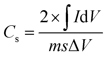
The modification of PET-g-PAA and PVDF-HFP_GO@PET-g-PAA samples is crucial for optimizing their performance in supercapacitor applications. One critical aspect to assess during this modification process is the constriction of pore diameter. This metric directly impacts ion conductivity and overall device efficiency, making it essential to monitor how grafting influences the pore structure. Scanning Electron Microscopy (SEM) was employed to study changes in pore diameter during the grafting process. The SEM micrographs presented in Fig. 2 reveal a slight narrowing of channels post-grafting with acrylic acid, indicating successful surface modification while maintaining open pores—a key feature for ion transport in supercapacitor applications which directly impacts ion conductivity and overall electrochemical performance. Further SEM analysis of the grafted surfaces (Fig. 2c and d) revealed significant morphological changes, with the surface becoming rougher and exhibiting small polymer clusters. This increased roughness suggests the formation of PAA chains on the surface, resulting from the RAFT-mediated grafting process. The whole coverage of the surface can enhance interaction with electrospun fibers in subsequent modifications and provide better ion transport and charge storage capabilities. The increased presence of carboxyl (–COOH) groups on the grafted copolymers was quantified using colorimetric analysis with Toluidine Blue O (TBO) dye, confirming the successful grafting process.48,49 The results depicted in Fig. 2a (red line) demonstrate a clear increase in PAA chain concentration as the polymerization time increases, a trend that is crucial for enhancing the functional properties of the membrane, particularly in terms of ion exchange capacity and hydrophilicity. | ||
| Fig. 2 The effect of irradiation time on the degree of grafting measured gravimetrically, black line, and the concentration of carboxyl groups, quantified by colorimetric analysis, red line (a). SEM images of the pristine PET TeM (b), PAA-grafted PET TeM (PET-g-PAA) (c), and a cross-sectional view of the PET-g-PAA membrane (d). | ||
To further validate the successful grafting of acrylic acid onto PET, Fourier Transform Infrared (FTIR) spectroscopy was conducted, with results presented in Fig. 3a and b. The FTIR spectra of modified PET films with a grafting degree (GD) of 17.84% show new peaks corresponding to O–H (centered at 2965 cm−1), C![[double bond, length as m-dash]](https://www.rsc.org/images/entities/char_e001.gif) O (1710 cm−1), and C–H (1260 cm−1) vibrations, all attributable to PAA. The significant increase in absorption at 1710 cm−1, associated with carboxyl groups, underscores the successful surface functionalization and correlates with the colorimetric analysis discussed earlier. The grafting step plays a pivotal role in enhancing the surface properties of the membrane, particularly its hydrophilicity and ion conductivity, which is vital for ensuring effective electrolyte interaction in supercapacitor applications. Additionally, FTIR analysis of the PVDF-HFP_GO nanofibers (Fig. 3c) identified characteristic peaks at 486 cm−1 and 861 cm−1 (α phase) and at 1395 cm−1 (C–F stretching), confirming the presence of the PVDF-HFP copolymer.50 The peaks at 1592 cm−1 (CO stretching), 3640 cm−1 (O–H stretching), 1399 cm−1 (O–H bending), and 3852 cm−1 (CH2 stretching) belong to the GO structure.51,52 The slight appearance of these peaks in the composite nanofiber spectrum verifies the successful incorporation of GO into the PVDF-HFP matrix.
O (1710 cm−1), and C–H (1260 cm−1) vibrations, all attributable to PAA. The significant increase in absorption at 1710 cm−1, associated with carboxyl groups, underscores the successful surface functionalization and correlates with the colorimetric analysis discussed earlier. The grafting step plays a pivotal role in enhancing the surface properties of the membrane, particularly its hydrophilicity and ion conductivity, which is vital for ensuring effective electrolyte interaction in supercapacitor applications. Additionally, FTIR analysis of the PVDF-HFP_GO nanofibers (Fig. 3c) identified characteristic peaks at 486 cm−1 and 861 cm−1 (α phase) and at 1395 cm−1 (C–F stretching), confirming the presence of the PVDF-HFP copolymer.50 The peaks at 1592 cm−1 (CO stretching), 3640 cm−1 (O–H stretching), 1399 cm−1 (O–H bending), and 3852 cm−1 (CH2 stretching) belong to the GO structure.51,52 The slight appearance of these peaks in the composite nanofiber spectrum verifies the successful incorporation of GO into the PVDF-HFP matrix.
 | ||
| Fig. 3 FTIR spectra of PET-g-PAA in the range of 4000–500 cm−1 (a) and 4000–2000 cm−1 (b), FTIR spectra of PVDF-HFP_GO nanofibers (c) and C1s core level XPS spectra of pristine PET TeM, PAA grafted membrane and PVDF-HFP_GO@PET-g-PAA membranes (d). | ||
The analysis of the C1s XPS core-level spectra (Fig. 3d) provides detailed insights into the chemical structure and surface modifications of the PET TeMs throughout the different stages of modification. In the case of the pristine TeMs, three primary components are observed in the C1s spectrum, each corresponding to distinct carbon environments. The dominant peak around 284.8 eV can be attributed to carbon–carbon (C–C) bonds, which represent the backbone structure of the PET polymer. Additionally, two notable peaks emerge at approximately 286.5 eV and 288.9 eV, corresponding to oxygenated carbon species, specifically carbonyl (CO) and ester (OC–O) functionalities, respectively, which are characteristic of the PET structure.53
Upon grafting PAA onto the membrane, an increase in oxygenated carbon species is observed. The increased signal intensity at these binding energies strongly suggests that the grafting process successfully modified the PET surface, increasing the density of oxygen-containing groups and altering the overall surface chemistry of the membrane. When further modifications were introduced by the incorporation of electrospun composite nanofibers composed of PVDF-HFP and GO, the presence of PVDF-HFP is demonstrated by the emergence of a distinct peak at approximately 292 eV, which corresponds to the carbon atoms bonded to fluorine (C–F).54.
This peak is a strong indication that the electrospun nanofibers have successfully adhered to the surface of the PAA-grafted membrane, confirming the effective deposition of the fluorinated nanofibers on the membrane. Moreover, the addition of GO is further corroborated by the observed increase in the intensity of the oxygenated carbon species, particularly the C–O peak around 286 eV. This increase is likely due to the rich oxygen-containing functional groups present on the GO nanosheets, such as hydroxyl (C–OH) and epoxy (C–O–C) groups. The changes in the C1s spectra, particularly the increased intensity of the C–O peak, align with the known structure of GO, suggesting that the GO is well integrated into the electrospun fiber matrix and contributes to the overall chemical composition of the surface.
Hydrophilicity is a crucial factor for membrane performance, as it directly influences wettability and electrolyte absorption. Dynamic water contact angle measurements, summarized in Fig. 4, revealed a substantial decrease in contact angle with increasing degrees of acrylic acid grafting. For instance, PET-g-PAA with a grafting degree of 17.84% exhibited a contact angle of 21.29 ± 1.91°, a significant reduction from 83.3° observed for pristine PET. This enhanced hydrophilicity is directly linked to the increased presence of –COOH groups, making the membrane more suitable for applications requiring efficient ion transport, such as supercapacitors.
 | ||
| Fig. 4 Water contact angle of pristine PET TeMs (a) and PAA grafted PET TeMs for 45 min (grafting degree: 6.35%) (b) and 90 min (grafting degree: 17.84%) (c). | ||
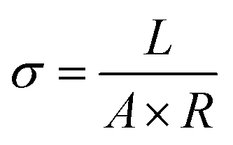
The morphological and elemental composition of the modified membranes was further characterized using SEM coupled with energy-dispersive X-ray spectroscopy (EDS), as shown in Fig. 5. The SEM analysis revealed uniform fiber diameters in the nano range from 40 to 180 nm, which is crucial for maintaining high porosity and surface area—both essential parameters for optimizing supercapacitor performance. The absence of GO agglomeration or irregular droplet-like formations within the fibers demonstrates that the fabrication process was well-controlled and critical for achieving consistent membrane performance.55 The EDS mapping identified carbon and fluorine within the nanofibers (Fig. 5c), consistent with the known chemical structure of PVDF-HFP. Additionally, the detection of significant oxygen content, an element absent in PVDF-HFP, confirms the successful incorporation of GO into the composite. This incorporation is critical for enhancing both the conductivity and mechanical strength of the material. Importantly, the pores of the underlying PAA-grafted membrane remained accessible, as shown in Fig. 5a, which supports efficient ion transport across the membrane structure and contributes to its enhanced electrochemical properties.
 | ||
| Fig. 5 SEM images of PVDF-HFP_GO@PET-g-PAA (a) 5 min, (b) 10 min, (c) 15 min; the corresponding size distributions and elemental mappings of composite nanofibers. | ||
Thermal stability is another crucial factor in assessing membrane performance for supercapacitor applications, as it dictates the membrane's durability under operating conditions. The thermogravimetric (TGA) analysis and differential thermogravimetric (DTG) curves, depicted in Fig. 6, shed light on the thermal behavior of the modified membranes. A slight weight increase observed in the early stage of degradation (25–300 °C) can be attributed to the buoyancy effect of the TGA equipment.56 This buoyancy effect, which results in an apparent mass gain during the initial heating stage, is caused by the aerodynamic drag of gas flow through the furnace, as detailed in previous studies.57 The high residual weights at 600 °C can be explained by the presence of thermally stable components, such as GO58 and the fluorinated polymer PVDF-HFP,59 which do not fully degrade at this temperature. The TGA thermogram for PET TeM-g-PAA reveals a maximum decomposition temperature of around 430.8 °C, accompanied by a weight loss of 47.96%. This behavior aligns with known PET thermal degradation mechanisms, which involve random scission of ester linkages and oligomer formation.60
 | ||
| Fig. 6 TGA curves of the composites: (a) thermogram of weight loss percentage in the temperature range of 25 to 600 °C; (b) derivative of weight loss depending on the temperature. | ||
Typically, PET degradation is marked by a sharp weight loss beyond 400 °C, though this can vary depending on the sample's background, such as its morphology and the thermal or mechanical processing conditions.53,61 In our case, PET samples were subjected to heavy ion irradiation, leading to degradation along the membrane, which consequently reduced the thermal stability of the material, resulting in a slightly lower maximum thermal degradation temperature than generally reported for PET. Notably, the PAA-grafted membrane with electrospun PVDF-HFP nanofibers exhibited a second degradation pattern shoulder around 470 °C, closely matching the decomposition profile of pure PVDF-HFP, which is reported to occur at approximately 475 °C.62 This finding confirms the presence and contribution of PVDF-HFP in the composite membrane.
Finally, the porosity and pore size distribution were assessed using Brunauer–Emmett–Teller (BET) analyses, with results indicating a type IV isotherm according to IUPAC classification.63 The hysteresis loop observed in the adsorption/desorption isotherm (Fig. 7) suggests the presence of mesopores,63 which are critical for facilitating ion transport in supercapacitor applications. The gradual increase in adsorption at low relative pressures (P/P0 = 0.01) further supports the presence of mesoporous interiors, which are beneficial for achieving high ion exchange rates and improved electrochemical performance.64 The quantitative BET analysis, summarized in Table 1, demonstrates the effective optimization of surface area, pore size, and volume in the composite membranes, directly contributing to their enhanced supercapacitor performance.
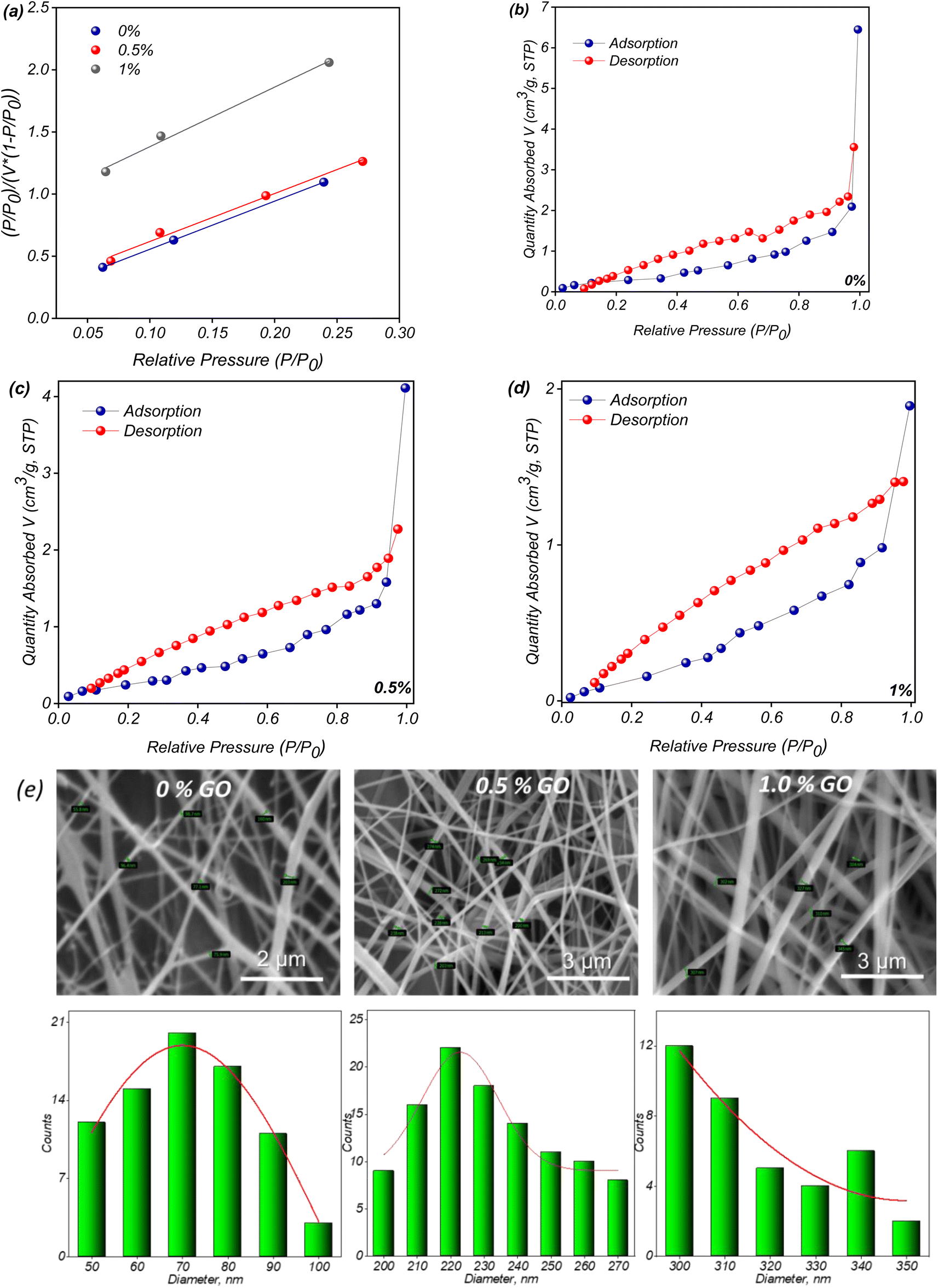 | ||
| Fig. 7 BET-adsorption plot (a) and N2 adsorption–desorption isotherm of PVDF-HFP_GO@PET-g-PAA membranes with different GO content of (b) 0%, (c) 0.5%, (d) 1%, the SEM images and corresponding size distributions composite nanofibers with different amount of GO (e). | ||
| GO content | 0% | 0.5% | 1% |
| BET surface area, m2 g−1 | 1.0779 | 1.0642 | 0.7644 |
| Langmuir surface area, m2 g−1 | 1.5897 | 1.6453 | 1.2918 |
| Total pore volume, cm3 g−1 | 0.0099 | 0.0063 | 0.0029 |
| Average pore width, nm | 37.0013 | 23.9000 | 15.3066 |
Decreasing in BET surface area with addition of GO to the nanofiber composition is caused be changing of fiber diameters during electrospinning stage. It was confirmed by analysis of the PVDF-GFP-OG nanofibers SEM images presented on the Fig. 8e. Using Phenom Image Viewer software the fibers diameters were examined and corresponding size distribution was calculated to be around 70 ± 10 nm for fibers without addition of GO, 220 ± 20 and 310 ± 10 nm for nanofibers with the GO content of 0.5 and 1.0% respectively.
 | ||
| Fig. 8 Cyclic voltammetry (CV) curves of pristine PET film (scan rate 3 mV s−1) (a), PAA-grafted TeM (scan rate 3 mV s−1) (b), and solid-state polymer supercapacitors based on varying GO content at different scan rates: 0% GO (c), 0.1% GO (d), 0.5% GO, (e) 1% GO (f). | ||
3.2 Electrochemical performance
For the electrochemical performance tests, materials at each functionalization step were evaluated. As shown in Fig. 8a, the cyclic voltammetry (CV) curve of the pristine PET track-etched membrane (TeM) without any grafting or electrospun fiber modification displays a highly underwhelming performance, as expected.The CV profile is nearly linear, with small current responses, indicating poor electrochemical activity and the absence of capacitive behavior. This is characteristic of unmodified PET TeMs, which lack the ionic conductive pathways necessary for efficient charge storage and ion transport, leading to negligible capacitance. Furthermore, the minimal slope of the current response in the CV curve shows that PET's inherent structure lacks electrochemically active sites, essential for supporting charge accumulation. Pristine PET, known for its insulating properties and lack of surface functional groups, is thus unsuitable for applications requiring significant energy storage or efficient ion diffusion. However, after grafting poly(acrylic acid) (PAA) onto the membrane, an improvement in electrochemical performance is observed (Fig. 8b). The PAA grafts, which are anchored throughout the nanopores and along the entire surface of the membrane, introduce ionic conductive groups. These carboxylic acid moieties impart enhanced ion conduction to the PET TeMs. Despite this improvement, the performance remains below the desired threshold for supercapacitor applications, which typically require specific capacitances above 100 F g−1 and energy densities exceeding 1 W h kg−1 for practical implementation.65,66 The observed performance is limited due to incomplete ionic transport pathways and suboptimal electrode/electrolyte interactions, as discussed in previous studies.67–69 To further enhance performance, we electrospun ionic gel fibers onto either one or both sides of the PAA-grafted PET TeMs under identical experimental conditions. Fig. 8c–f presents the CV curves of supercapacitors fabricated from PAA-grafted PET TeMs, where only one side was modified with ionic gel fibers. The curves, measured across a range of scan rates (from 1 mV s−1 to 100 mV s−1), demonstrate a significant increase in electrochemical performance. The nearly rectangular shape of these CV curves is indicative of excellent capacitive behavior, and the larger areas under the curves correspond to higher capacitance values, a hallmark of efficient ion transport and charge storage. At the lowest GO concentration (0.1 wt%), the electrochemical performance of the membrane slightly enhanced as seen in Fig. 8d, indicating that the added amount of GO is insufficient to establish a continuous conductive pathway, leading to inefficient charge storage.
Fig. 8e shows that the membrane modified with 0.5% GO-modified membrane displayed the highest electrochemical performance. The enhanced specific capacitance at 0.5 wt% GO could be due to an optimal balance between GO dispersion and conductive network formation. At this concentration, GO may provide sufficient conductive sites within the PVDF-HFP matrix while maintaining interconnectivity that promotes efficient ion transport. The partial deviation from an ideal rectangular CV profile suggests that 0.5 wt% GO creates a microstructure that maximizes accessible surface area for charge storage but also induces some degree of resistance due to mild aggregation. This slight aggregation might lead to localized regions of higher conductivity, effectively increasing the specific capacitance by allowing more ions to interact with the surface without significantly impeding overall charge transport. At this concentration, GO may form an optimal structure where both double-layer capacitance and limited pseudocapacitive reactions occur simultaneously. The slight aggregation at 0.5 wt% could lead to more interaction points, thereby facilitating limited redox activity while still maintaining efficient ion transport. Conversely, at 1 wt% GO, while the CV profile remains rectangular, the high loading may cause over-saturation of GO, reducing the electroactive surface area as GO sheets overlap or stack. This excessive overlap limits the available surface for ion adsorption, which may explain why the capacitance does not reach the level observed at 0.5 wt%. At 1 wt% GO, the nearly rectangular CV curves suggest dominant electrical double-layer capacitance (EDLC). This behavior typically arises in materials like graphene oxide, where the energy storage is primarily through the adsorption and desorption of ions at the electrode surface without faradaic (redox) reactions.70 Similar behavior highlighting the importance of optimizing GO loading to balance ionic conductivity with structural integrity has been observed in other GO-polymer composites.71 Fig. 8a–d further illustrate that as the scan rate increases, the CV areas expand, signifying enhanced ion transport within the polymer matrix. Even at higher scan rates, most of the curves maintain a nearly rectangular shape, reaffirming the robust capacitive nature of the modified membranes across various GO concentrations and scan rates. This consistent performance at different scan rates highlights the stability and efficiency of the system in fast charge–discharge cycles, which is critical for high-performance supercapacitors. The CV analysis emphasizes the critical role of both PAA grafting and the modification with electrospun ionic gel fibers in achieving promising electrochemical performance in PET TeM-based supercapacitors.
The relationship between capacitance and scan rate is depicted in Fig. 9, showing a downward trend with increasing scan rate.
 | ||
| Fig. 9 Dependence of the specific capacitance on the scan rate for PVDF-HFP_GO@PET-g-PAA with the different concentrations of GO. | ||
The concentration of GO had a notable effect on the specific capacitance of the supercapacitors. At a scan rate of 3 mV s−1, the specific capacitances for PVDF-HFP_GO@PET-g-PAA membrane supercapacitors, modified with nanofibers containing GO concentrations of 0.1%, 0.5%, and 1.0 were 4.3 ± 0.3 F g−1, 10.3 ± 0.5 F g−1, and 8.4 ± 0.6 F g−1, respectively. This indicates that 0.5% GO was the optimal concentration, consistent with the earlier discussion of the CV curves. Additionally, as the scan rate increased, the specific capacitance decreased. This behavior can be attributed to the fact that lower scan rates provide more time for ions to diffuse deeply into the electrode structure, enhancing the capacitive properties.72 The specific capacitance of the grafted film without nanofibers (PAA-g-PET) was significantly lower, reaching only 0.048 F g−1 at 3 mV s−1 and decreasing to 0.001 F g−1 at a scan rate of 100 mV s−1. In contrast, the pristine PET TeMs exhibited an extremely low specific capacitance of 0.004 F g−1 at 3 mV s−1. This data emphasizes the considerable improvement in electrochemical performance achieved in two stages: first, through the grafting process, and more notably, with the incorporation of GO nanofibers into the membranes, which had a particularly pronounced effect.
To further assess the performance of the PVDF-HFP_GO@PET-g-PAA supercapacitors, galvanostatic charge–discharge (GCD) tests were conducted (Fig. 10). The results indicate that the membranes modified with 0.5% and 1.0% GO-containing nanofibers exhibited significantly longer charge–discharge times compared to other samples, highlighting their superior capacitance performance.73 The longer charge–discharge times observed for samples with 0.5% and 1.0% GO are indicative of higher specific capacitance. At these concentrations, the presence of GO likely enhances the electrode's surface area and introduces additional pathways for ion transport and charge storage, especially through both double-layer formation and possibly some pseudocapacitive reactions, thanks to the oxygenated functional groups in GO. The longer charge–discharge duration suggests that these samples can store and release more energy compared to the samples with lower GO content.74 The highest performance at 0.5% GO is significant. At this concentration, GO likely achieves an optimal distribution within the PVDF-HFP matrix, balancing surface area, conductivity, and accessibility for electrolyte ions. This optimal dispersion can facilitate ion transport while minimizing agglomeration effects that might limit performance. This contrasts with 1.0% GO, where excessive GO may begin to reduce effective surface area due to partial aggregation, thus slightly lowering the overall capacitance despite maintaining a relatively high charge–discharge time.75 This observation aligns with previous studies demonstrating that aggregated GO particles have fewer available active sites and a lower surface-area-to-volume ratio compared to well-dispersed GO, thereby reducing reactivity and performance.71,76–78 All GCD curves display an isosceles triangular shape, indicative of high coulombic efficiency and typical capacitor behavior, suggesting minimal energy loss during charge–discharge cycles. This shape, along with consistent discharge patterns, points to stable capacitive behavior across the samples, reinforcing that the system behaves as an ideal capacitor with efficient charge storage and release. The GCD profiles also demonstrate consistent discharge patterns, with most samples achieving stable coulombic activity across different GO concentrations, indicating that the supercapacitors retain good energy storage efficiency, with minimal degradation or faradaic side reactions that could otherwise affect cycle life and stability.79
 | ||
| Fig. 10 Galvanostatic charge–discharge (GCD) curves of SSC with varying GO content at two different current densities of 0.5 and 1.0 A g−1: 0% GO (a), 0.1% GO (b), 0.5% GO (c), 1% GO (d) and specific capacity vs. cycle number for the different compositions (e). | ||
As illustrated in Fig. 10e the capacitive behavior shows a common trend across the different GO percentages, with discharge capacity stabilizing early on and reaching a maximum of around 200–300 cycles. This consistent performance across multiple cycles suggests that the GO incorporated in the matrix plays a crucial role in sustaining conductivity. Among the tested samples, the SSC with 0.5% GO exhibited the highest capacity, solidifying its status as the optimal composition for maximizing electrochemical performance.
The impedance behaviour of the samples was also evaluated through electrochemical impedance spectroscopy (EIS) (Fig. 11). The real part of the impedance (Z′) decreases as frequency increases, stabilizing around 2 kHz and becoming frequency-independent thereafter. This reduction in impedance with increasing frequency suggests enhanced conductivity, while the higher Z′ values at lower frequencies are indicative of greater polarization within the hybrid TeM structure, as all types of polarization are active at lower frequencies. The convergence of Z′ values at higher frequencies reflects the potential release of space charge polarization, a typical feature in such materials.80 Additionally, the low-frequency region with higher Z′ values indicates significant interfacial polarization, suggesting that ion mobility is restricted at low frequencies due to the structural complexity of the membrane. This phenomenon is typically associated with the presence of GO, which introduces additional interfaces that can hinder ionic transport, especially at low frequencies where polarization effects dominate.81
 | ||
| Fig. 11 Variation of the real part of impedance (Z′) as a function of frequency for solid-state supercapacitors with different GO content (a), coulombic efficiency of supercapacitors with different GO contents (0.5% and 1%) over cycling (b), and Nyquist plot of the EIS tests (c). | ||
The coulombic efficiency of the supercapacitors containing 0.5% and 1% GO (Fig. 11b) was evaluated over multiple charge–discharge cycles. Both systems initially demonstrated efficiencies above 75%. However, significant degradation in performance was observed after around 500 cycles. The supercapacitor with 0.5% GO exhibited a more gradual decline in efficiency, though the decrease began at an earlier stage compared to the 1% GO sample. In contrast, the supercapacitor with 1% GO maintained higher efficiency for a longer period but then experienced a sharp and rapid decline after about 500 cycles. This degradation in performance for both supercapacitors suggests that, although the inclusion of GO enhances the capacitive behavior, long-term cycling stability is still a challenge. The sharp drop in efficiency observed in the 1% GO system is likely due to factors such as increased internal resistance or the agglomeration of GO particles at higher concentrations. Such agglomeration could hinder ion diffusion within the electrode structure, disrupting charge transfer and ultimately leading to poor charge retention over extended cycles.
These findings emphasize the importance of optimizing the GO content to balance initial performance with long-term stability, as excessive GO can introduce structural limitations that impair cycling durability. For instance, after 550 cycles, a more than 90% reduction in efficiency was observed in the membrane with 1% GO containing nanofibers, indicating destructive phenomena within the membrane structure. To investigate this further, SEM analysis was conducted to examine the surface morphology of the samples (see Fig. 12), revealing a significant deterioration in the homogeneity of PVDF-HFP_GO fibers following electrochemical testing, which contributed to the decrease in long-term stability. Moreover, the observed structural breakdown in the 1% GO sample suggests that high GO concentrations may accelerate mechanical fatigue within the fiber matrix, leading to localized disruptions in fiber integrity and, consequently, greater impedance. This mechanical degradation is likely exacerbated by repeated ion intercalation and deintercalation cycles, particularly at interfaces where GO is less evenly dispersed. These findings highlight the need for further modifications, such as surface treatments or optimized GO dispersion techniques, to ensure better long-term performance.82
 | ||
| Fig. 12 SEM images of the single-side covered with 0.5% GO nanofibers GPE TeM after 600 cycles of testing at the different magnifications. | ||
The total ionic conductivity of the GPE TeMs was evaluated using electrochemical impedance spectroscopy (EIS). The Nyquist plot of PVDF-HFP_GO with varying GO concentrations, presented in Fig. 11c, shows typical GPE behavior. The impedance plot comprises a single semi-circle for all the measured samples, indicating that the resistances are primarily due to the grain properties of the GPE TeMs. Notably, the PVDF-HFP_GO sample with 0.5% GO exhibited a smaller semicircular diameter, signifying that GO plays a key role in improving the conductivity of the supercapacitors. The ionic conductivity, a crucial parameter that reflects the ionic transport capacity of electrolytes83 was calculated from the Nyquist plot and is presented in Table 2. Ionic conductivity increased with the addition of GO in the GPE TeM composition up to a concentration of 0.5%, after which it decreased when the GO concentration reached 1.0%. This behavior aligns with the above results and can be explained by the uniform distribution of graphene oxide up to a critical concentration of 0.5%. Beyond this concentration, agglomeration of GO occurs, leading to reduced ionic transport. It is well-documented that non-agglomerated graphene oxide sheets possess lower bulk resistance due to their mobility within the gel, resulting in improved ionic conductivity.17,84 The ionic conductivity of the hybrid membranes with 0.5% GO reached 14.83 × 10⁻³ mS cm−1 for single-sided nanofiber-covered membranes and 39.08 × 10⁻³ mS cm−1 for double-sided configurations. These values are significantly higher than those of conventional polymer-based electrolyte membranes (∼10−4 to 10−2 mS cm−1)85,86 and comparable to advanced ionic gel-based systems (∼10−2 to 10−1 mS cm−1).87–89
| GO content in PVDF-HFP_GO@PET-g-PAA (%) | Ionic conductivity, σ × 10−3 (mS cm−1) |
|---|---|
| 0 | 1.42 |
| 0.1 | 1.95 |
| 0.5 | 14.83 |
| 1.0 | 5.37 |
The results of electrical conductivity are given in Table 3. For the sample without GO, the conductivity supplied by grafted PAA chains is relatively low, indicating that the grafted polymer matrix alone has limited electrical conductivity. Adding a small amount of GO (0.1%) slightly increases the conductivity. This improvement can be attributed to the introduction of conductive pathways due to GO, even at a low concentration. GO has conductive properties, so even a small addition can help create paths for electron movement within the composite.
| GO content in PVDF-HFP_GO@PET-g-PAA (%) | Charge transfer resistance (ohm) | Thickness (cm) | Contact area (cm2) | Electrical conductivity (mS cm−1) |
|---|---|---|---|---|
| 0 | 2827.48 | 0.0015 | 2.0106 | 0.26 × 10⁻³ |
| 0.1 | 2320.18 | 0.0017 | 2.0106 | 0.36 × 10⁻³ |
| 0.5 | 733.50 | 0.0017 | 2.0106 | 1.15 × 10⁻³ |
| 1.0 | 1837.34 | 0.0019 | 2.0106 | 0.50 × 10⁻³ |
At 0.5% GO, there's a substantial increase in conductivity, suggesting that the network of GO within the polymer matrix has become more interconnected, enhancing the overall electrical conductivity of the composite. This could indicate a threshold concentration, where a percolating network of GO forms, allowing a continuous conductive path throughout the material. At 1% GO, the conductivity decreases to 0.5 S m−1, lower than that at 0.5% GO. This decrease could result from excessive GO aggregation, which disrupts the conductive pathways. High concentrations of GO can sometimes lead to particle clustering, reducing the effective contact between GO particles and disrupting the formation of a consistent conductive network. The results suggest that there is an optimal concentration of GO in the polymer matrix for maximizing electrical conductivity. In this case, 0.5% GO appears to be close to the optimal concentration, where the GO particles form a well-connected network, enhancing conductivity. Adding too much GO (e.g., 1%) may lead to agglomeration, which can disrupt conductivity by decreasing the uniform distribution of GO throughout the polymer.90,91 Bode plots typically illustrate the relationship between impedance magnitude (|Z|) and phase angle (θ) as a function of frequency, providing insights into the frequency response and behavior of each supercapacitor configuration (Fig. 13).92,93 The Bode plot of the supercapacitor without GO typically shows relatively high impedance across a wide frequency range, indicating a limited conductivity and ion mobility within the structure. The phase angle remains close to 0° at low frequencies, pointing to resistive behavior and minimal capacitive response, likely due to the absence of GO's conductive pathways. At higher frequencies, the impedance magnitude may start to decrease, but overall, the lack of GO limits charge transfer and overall electrochemical activity.94,95 With 0.1% GO (Fig. 13b), a slight improvement in impedance response emerges as conductive pathways begin forming within the PVDF-HFP matrix. The phase angle shift suggests a modest increase in capacitive behavior, though still below optimal performance. At low frequencies, the phase angle might indicate both resistive and capacitive characteristics due to insufficient GO to fully establish effective charge pathways and ion movement.96 At 0.5% GO concentration (Fig. 13c), the Bode plot typically shows a significant decrease in impedance at both low and intermediate frequencies, reflecting improved conductivity due to optimized GO dispersion within the matrix. The phase angle may approach −45° at certain frequencies, indicating a more balanced capacitive behavior that suggests enhanced charge storage and transfer properties. This configuration likely achieves the best compromise between resistive and capacitive performance, explaining why the 0.5% GO content often yields the highest specific capacitance, as evidenced by earlier electrochemical tests.97 With further increased GO (1% wt – Fig. 13d), impedance reduction at high frequencies is seen, but low-frequency impedance may increase slightly due to potential GO agglomeration. This phase angle fluctuation suggests inconsistent capacitive behavior, likely due to ion movement hindrance from agglomerated GO. Although conductivity may initially seem high, the agglomeration can lead to non-uniform charge distribution and ion blocking, reducing effective capacitance and efficiency over time.98
 | ||
| Fig. 13 Bode plot as a function of frequency for PVDF-HFP_GO@PET-g-PAA solid-state supercapacitors with various GO content: 0% GO (a), 0.1% GO (b), 0.5% (c), 1% GO (d). | ||
The leakage current test results in Fig. 14 reveal varied behaviors across different graphene oxide (GO) concentrations, highlighting the influence of GO content on the PVDF-HFP_GO@PET-g-PAA membrane. For the sample without GO, the leakage current shows a steady reduction over time, indicating a low-leakage profile due to the absence of additional conductive pathways, which likely stabilizes the membrane structure. The low leakage in this sample aligns with the absence of conductive additives. At 0.1% GO, leakage current decreases further, suggesting even lower initial leakage compared to the 0% GO sample. This could be attributed to the sparse dispersion of GO, which may not form significant conductive paths and therefore limits ion migration. For the 0.5% GO sample, the leakage current reduction from over 300 seconds indicates a balance between conductive pathways and minimal charge loss, with a lower ending leakage current implying effective charge retention. This result aligns well with the EIS and CV data, suggesting 0.5% GO as an optimal concentration for balancing capacitance and leakage control. The 1% GO sample shows an initially high leakage current (∼12 mA), which decreases over time but remains relatively elevated, indicating significant charge loss. This high initial leakage could result from excess GO, potentially creating undesirable conductive pathways that increase leakage.99–101 These findings emphasize that GO content needs to be carefully optimized to enhance conductivity and capacitance without introducing excessive leakage. 0.5% GO appears to be the ideal concentration, achieving stable capacitive behavior as indicated by EIS (low impedance but high leakage resistance), CV (high current with distorted shape), and leakage current results.
 | ||
| Fig. 14 Leakage current as a function of time for PVDF-HFP_GO@PET-g-PAA solid-state supercapacitors with various GO content: 0% GO (a), 0.1% GO (b), 0.5% (c), 1% GO (d). | ||
The previously discussed results pertain to membranes with composite nanofibers applied to only one side of the surface. To further enhance the supercapacitor's capacity, PVDF-HFP_GO fibers containing 0.5% GO were spun onto both sides of the membrane. The advantages of this dual-sided fiber coating approach were highlighted in earlier studies,102 where it was shown to significantly improve surface area and electrochemical performance. As illustrated in Fig. 15, applying fibers on both sides of the grafted TeMs resulted in a marked improvement in electrochemical behavior. Specifically, Fig. 15a shows a 20% increase in capacitance, rising from 0.25 to 0.30. Additionally, Fig. 15b demonstrates that the operational lifetime of the supercapacitor extended from 600 to 980 cycles. This dual-sided fiber coating enhances ion accessibility and charge transfer efficiency, leading to superior energy storage and stability.
 | ||
| Fig. 15 GCD curves of SSC whose single-side and double-side covered with 0.5% GO containing nanofibers at a current density of 0.5 A g−1 (a), and specific capacity vs. cycle number for these two compositions (b). | ||
Consequently, ionic conductivity increased about 2.5 times, reaching 39.08 × 10⁻³ mS cm−1 after double-sided coating of the PAA-grafted PET TeM. By increasing the surface area for electrochemical reactions and improving the structural integrity of the membrane, this approach offers a significant step forward in optimizing supercapacitor performance.
Table 4 summarizes the performance of various GO-based GPE electrolytes. It can be observed that the PVDF-HFP_GO nanofiber-containing membranes developed in this study show performance levels comparable to those reported in previous studies. Although our results do not surpass the highest-performing examples in the literature, the flexibility and material stability of the PET substrate offer a significant advantage. These properties make the PVDF-HFP_GO@PET-g-PAA membranes a promising alternative for supercapacitor applications, with the potential for further optimization and enhancement.
| GO-based GPE | Ionic conductivity (mS cm−1) | Ref. |
|---|---|---|
| PVDF-HFP/PANI_GO ternary membrane | 6.64 × 10⁻⁴ | 51 |
| PVDF-HFP-PEO_GO | 2.1 | 79 |
| PVDF-HFP_GO (1.0% GO) | 1.90 × 10⁻⁴ | 52 |
| PVDF-HFP_GO (2.5% GO) | 4.23 × 10⁻⁴ | |
| PVDF-HFP_GO (5% GO) | 3.01 × 10⁻⁴ | |
| PVDF-HFP_5EMIMBF4_GO (1.0% GO) | 25.0 | 2 |
| PVDF-HFP_GO (0.2% GO) | 26.0 | 103 |
| PVDF-HFP_GO@PET-g-PAA (0.5% GO) | 39.08 × 10⁻³ | This study |
4 Conclusion
This study successfully developed a novel hybrid membrane by combining RAFT-mediated grafting of poly(acrylic acid) (PAA) onto PET track-etched membranes (TeMs) with the integration of electrospun composite nanofibers containing graphene oxide (GO) and poly(vinylidene fluoride-co-hexafluoropropylene) (PVDF-HFP). This two-stage modification process significantly enhanced the membrane's electrochemical performance while maintaining its inherent flexibility and mechanical stability, making it a promising candidate for flexible energy storage applications.The grafting of PAA onto the membrane surface and nanopore walls introduced ion-conductive pathways, while the incorporation of GO-doped nanofibers further improved surface area and ionic conductivity. The hybrid membrane with an optimal GO concentration of 0.5% demonstrated remarkable electrochemical properties, achieving a specific capacitance of 10.3 F g−1 at 3 mV s−1, a substantial improvement over the grafted membrane without nanofibers (0.05 F g−1) and the pristine TeM (0.004 F g−1). This highlights the synergistic effect of grafting and electrospinning, as well as the critical role of GO in enhancing ionic transport.
The ionic conductivity of the hybrid membranes reached 14.83 × 10⁻³ mS cm−1 for single-sided nanofiber-covered membranes and 39.08 × 10⁻³ mS cm−1 for double-sided configurations, significantly outperforming conventional polymer-based electrolyte membranes (∼10−4 to 10−2 mS cm−1). The optimal GO concentration also improved electronic conductivity, with Bode plots showing reduced impedance at low and intermediate frequencies, indicating enhanced ion transport due to well-dispersed GO within the polymer matrix. Additionally, the 0.5% GO sample exhibited reduced leakage current after 300 seconds, further confirming its stability.
Despite these advancements, performance degradation after 500 cycles and challenges at higher current densities highlight areas for future optimization. Key strategies include strengthening GO–polymer interactions, improving structural integrity under cycling stress, and exploring alternative polymer matrices or reinforcement techniques. These improvements will be crucial for enhancing durability and performance in practical applications. This study demonstrates the potential of combining RAFT-mediated grafting and electrospinning to develop advanced TeMs for energy storage. By refining polymer–fiber interactions and exploring new composite materials, future work can further enhance the performance and durability of these membranes, paving the way for next-generation flexible energy storage devices.
Abbreviations
| AA | Acrylic acid |
| ASSSCs | All-solid-state supercapacitors |
| BP | Benzophenone |
| CA | Contact angle |
| CV | Cyclic voltammogram |
| DMF | Dimethylformamide |
| EDX | Energy dispersive X-ray analysis |
| EIS | Electrochemical impedance spectroscopy |
| EMIMBF4 | 1-Ethyl-3-methylimidazolium tetrafluoroborate |
| GCD | Galvanostatic charge–discharge |
| GD | Grafting degree |
| GPE | Gel polymer electrolyte |
| FTIR | Fourier transform infrared spectroscopy |
| PET | Polyethylene terephthalate |
| PVDF-HFP | Poly(vinyledenefluoride) hexafluoropropylene |
| SEM | Scanning electron microscopy |
| XPS | X-ray photoelectron spectroscopy |
Data availability
The data presented in this study are available on request from the corresponding authors.Author contributions
Conceptualization, M. B., A. A. M.; methodology, A. A. M., and M. B.; validation, N. A. A., and Zh. A. M.; formal analysis, N. A. A., A. A. A., D. T. N., S. A. and Zh. A. M.; investigation, M. B., A. A. M., N. A. A., A. A. A., D. T. N., and Zh. A. M.; writing-original draft preparation, M. B., A. A. M., Zh. A. M., N. A. A. and S. A.; writing-review and editing, N. A. A., M. B. and A. A. M., S. A.; supervision, M. B., project administration, A. A. M.; funding acquisition, A. A. M. All authors have read and agreed to the published version of the manuscript.Conflicts of interest
The authors declare no conflicts of interest.Acknowledgements
This study was funded by the Ministry of Science and Higher Education of the Republic of Kazakhstan (Grant No. AP14869845). M. B. acknowledges Hacettepe University Scientific Research Projects Coordination Unit (FHD-2023-20201).References
- J. R. Miller and P. Simon, Electrochemical Capacitors for Energy Management, Science, 2008, 321(5889), 651–652 CrossRef CAS PubMed.
- X. Yang, et al., A high-performance graphene oxide-doped ion gel as gel polymer electrolyte for all-solid-state supercapacitor applications, Adv. Funct. Mater., 2013, 23(26), 3353–3360 CrossRef CAS.
- S. Sagadevan et al., Fundamental electrochemical energy storage systems, Advances in Supercapacitor and Supercapattery, Elsevier, 2021, pp. 27–43 Search PubMed.
- C. Huang, et al., Solid-state supercapacitors with rationally designed heterogeneous electrodes fabricated by large area spray processing for wearable energy storage applications, Sci. Rep., 2016, 6, 1–15 CrossRef PubMed.
- T. K. L. Nguyen and T.-N. Pham-Truong, Recent Advancements in Gel Polymer Electrolytes for Flexible Energy Storage Applications, Polymers, 2024, 16(17), 2506 CrossRef CAS PubMed.
- M. S. Ahmed, et al., A Comprehensive Review of Functional Gel Polymer Electrolytes and Applications in Lithium-Ion Battery, Gels, 2024, 10(9), 563 CrossRef CAS PubMed.
- X. Cheng, et al., Gel Polymer Electrolytes for Electrochemical Energy Storage, Adv. Energy Mater., 2018, 8(7), 1702184 CrossRef.
- W. Ren, et al., Advanced gel polymer electrolytes for safe and durable lithium metal batteries: Challenges, strategies, and perspectives, Energy Storage Mater., 2021, 34, 515–535 CrossRef.
- K. S. Ngai, et al., A review of polymer electrolytes: fundamental, approaches and applications, Ionics, 2016, 22(8), 1259–1279 CrossRef CAS.
- M. Zhu, et al., Recent advances in gel polymer electrolyte for high-performance lithium batteries, J. Energy Chem., 2019, 37, 126–142 CrossRef.
- J. Chattopadhyay, T. S. Pathak and D. M. F. Santos, Applications of Polymer Electrolytes in Lithium-Ion Batteries: A Review, Polymers, 2023, 15(19), 3907 CrossRef CAS PubMed.
- Y. Fang, et al., Synthesis and biological evaluation of 1,2,4,5-tetrasubstituted imidazoles, Res. Chem. Intermed., 2017, 43(8), 4413–4421 CrossRef CAS.
- G. A. Tafete, M. K. Abera and G. Thothadri, Review on nanocellulose-based materials for supercapacitors applications, J. Energy Storage, 2022, 48, 103938 CrossRef.
- L. Lv, et al., Lamellar agarose/graphene oxide gel polymer electrolyte network for all-solid-state supercapacitor, Chem. Eng. J., 2023, 452(P3), 139443 CrossRef CAS.
- B. Liu, et al., A high-performance and environment-friendly gel polymer electrolyte for lithium ion battery based on composited lignin membrane, J. Solid State Electrochem., 2018, 22(3), 807–816 CrossRef CAS.
- A. Song, et al., Gel polymer electrolyte with high performances based on pure natural polymer matrix of potato starch composite lignocellulose, Electrochim. Acta, 2017, 245, 981–992 CrossRef CAS.
- S. Alipoori, et al., Graphene oxide: An effective ionic conductivity promoter for phosphoric acid-doped poly (vinyl alcohol) gel electrolytes, Polymer, 2019, 184, 121908 CrossRef CAS.
- Y. Yang, A mini-review: Emerging all-solid-state energy storage electrode materials for flexible devices, Nanoscale, 2020, 12(6), 3560–3573 RSC.
- Y.-T. Tleukenov, et al., Polyacrylonitrile-Polyvinyl Alcohol-Based Composite Gel-Polymer Electrolyte for All-Solid-State Lithium-Ion Batteries, Polymers, 2022, 14(23), 5327 CrossRef CAS PubMed.
- J. Wang, et al., High Performance Poly(vinyl alcohol)-Based Li-Ion Conducting Gel Polymer Electrolyte Films for Electric Double-Layer Capacitors, Polymers, 2018, 10(11), 1179 CrossRef PubMed.
- G. Wang, L. Zhang and J. Zhang, A review of electrode materials for electrochemical supercapacitors, Chem. Soc. Rev., 2012, 41(2), 797–828 RSC.
- X. Hou, et al., “Water-in-Eutectogel” Electrolytes for Quasi-Solid-State Aqueous Lithium-Ion Batteries, Adv. Energy Mater., 2022, 12(23), 2200401 CrossRef CAS.
- S. Chen, et al., Perchlorate Based “Oversaturated Gel Electrolyte” for an Aqueous Rechargeable Hybrid Zn–Li Battery, ACS Appl. Energy Mater., 2020, 3(3), 2526–2536 CrossRef CAS.
- W. Lu, et al., Incorporating Ionic Liquid Electrolytes into Polymer Gels for Solid-State Ultracapacitors, J. Electrochem. Soc., 2008, 155(5), A361 CrossRef CAS.
- Q. Yang, et al., The recent research progress and prospect of gel polymer electrolytes in lithium-sulfur batteries, Chem. Eng. J., 2021, 413, 127427 CrossRef CAS.
- D. He, et al., Engineered Graphene Materials: Synthesis and Applications for Polymer Electrolyte Membrane Fuel Cells, Adv. Mater., 2017, 29(20), 1601741 CrossRef PubMed.
- J. R. M. Nauman, et al., Recent developments in graphene and graphene oxide materials for polymer electrolyte membrane fuel cells applications, Renewable Sustainable Energy Rev., 2022, 168, 112836 CrossRef.
- Z. Hu, X. Zhang and S. Chen, A graphene oxide and ionic liquid assisted anion-immobilized polymer electrolyte with high ionic conductivity for dendrite-free lithium metal batteries, J. Power Sources, 2020, 477, 228754 CrossRef CAS.
- M. M. Taufiq, N. Shaari and S. K. Kamarudin, Carbon nanotube, graphene oxide and montmorillonite as conductive fillers in polymer electrolyte membrane for fuel cell: an overview, Int. J. Energy Res., 2021, 45(2), 1309–1346 CrossRef.
- S. Gahlot and V. Kulshrestha, Graphene based polymer electrolyte membranes for electro-chemical energy applications, Int. J. Hydrogen Energy, 2020, 45(34), 17029–17056 CrossRef CAS.
- K. Javed, et al., A Review on Graphene-Based Electrospun Conductive Nanofibers, Supercapacitors, Anodes, and Cathodes for Lithium-Ion Batteries, Crit. Rev. Solid State Mater. Sci., 2019, 44(5), 427–443 CrossRef CAS.
- J. Liang, et al., Recent advances in electrospun nanofibers for supercapacitors, J. Mater. Chem. A, 2020, 8(33), 16747–16789 RSC.
- Q. Liu, et al., Recent advances in energy materials by electrospinning, Renewable Sustainable Energy Rev., 2018, 81, 1825–1858 CrossRef CAS.
- X. Li, et al., Electrospun carbon-based nanostructured electrodes for advanced energy storage – A review, Energy Storage Mater., 2016, 5, 58–92 CrossRef.
- M. Liu, et al., A Review: Electrospun Nanofiber Materials for Lithium-Sulfur Batteries, Adv. Funct. Mater., 2019, 29(49), 1905467 CrossRef CAS.
- Q. Dong, et al., Electrospun Composites Made of Reduced Graphene Oxide and Activated Carbon Nanofibers for Capacitive Deionization, Electrochim. Acta, 2014, 137, 388–394 CrossRef CAS.
- T. Lavanya, et al., Superior photocatalytic performance of reduced graphene oxide wrapped electrospun anatase mesoporous TiO 2 nanofibers, J. Alloys Compd., 2014, 615, 643–650 CrossRef CAS.
- J. Wan, et al., Ultrathin, flexible, solid polymer composite electrolyte enabled with aligned nanoporous host for lithium batteries, Nat. Nanotechnol., 2019, 14(7), 705–711 CrossRef CAS PubMed.
- A. A. Mashentseva, et al., Composite Track-Etched Membranes: Synthesis and Multifaced Applications, Polymers, 2024, 16(18), 2616 CrossRef CAS PubMed.
- N. A. Kumar, et al., Polyaniline-Grafted Reduced Graphene Oxide for Efficient Electrochemical Supercapacitors, ACS Nano, 2012, 6(2), 1715–1723 CrossRef CAS PubMed.
- H. J. Min, et al., Excellent film-forming, ion-conductive, zwitterionic graft copolymer electrolytes for solid-state supercapacitors, Chem. Eng. J., 2021, 412, 127500 CrossRef CAS.
- D. A. Kang, et al., High-performance solid-state bendable supercapacitors based on PEGBEM-g-PAEMA graft copolymer electrolyte, Chem. Eng. J., 2020, 384, 123308 CrossRef CAS.
- P. Su, et al., Graphene oxide membranes: controlling their transport pathways, J. Mater. Chem. A, 2020, 8(31), 15319–15340 RSC.
- I. V. Korolkov, et al., Enhancing hydrophilicity and water permeability of PET track-etched membranes by advanced oxidation process, Nucl. Instrum. Methods Phys. Res., Sect. B, 2015, 365, 651–655 CrossRef CAS.
- N. Parmanbek, et al., e-Beam and γ-rays Induced Synthesis and Catalytic Properties of Copper Nanoclusters-Deposited Composite Track-Etched Membranes, Membranes, 2023, 13(7), 659 CrossRef CAS PubMed.
- I. V. Korolkov, et al., UV-induced graft polymerization of acrylic acid in the sub-micronchannels of oxidized PET track-etched membrane, Nucl. Instrum. Methods Phys. Res., Sect. B, 2015, 365, 419–423 CrossRef CAS.
- L. Altynbaeva, et al., A Novel Cu2O/ZnO@PET Composite Membrane for the Photocatalytic Degradation of Carbendazim, Nanomaterials, 2022, 12(10), 1724 CrossRef CAS PubMed.
- J. Chen, et al., Biocompatibility studies of poly(ethylene glycol)-modified titanium for cardiovascular devices, J. Bioact. Compat. Polym., 2012, 27(6), 565–584 CrossRef.
- I. B. Muslimova, et al., Preparation and application of stimuli-responsive PET TeMs: RAFT graft block copolymerisation of styrene and acrylic acid for the separation of water-oil emulsions, RSC Adv., 2024, 14(20), 14425–14437 RSC.
- S. Shalu, V. K. Singh and R. K. Singh, Development of ion conducting polymer gel electrolyte membranes based on polymer PVdF-HFP, BMIMTFSI ionic liquid and the Li-salt with improved electrical, thermal and structural properties, J. Mater. Chem. C, 2015, 3(28), 7305–7318 RSC.
- A. L. Ahmad, U. R. Farooqui and N. A. Hamid, Porous (PVDF-HFP/PANI/GO) ternary hybrid polymer electrolyte membranes for lithium-ion batteries, RSC Adv., 2018, 8(45), 25725–25733 RSC.
- A. L. Ahmad, U. R. Farooqui and N. A. Hamid, Effect of graphene oxide (GO) on Poly(vinylidene fluoride-hexafluoropropylene) (PVDF- HFP) polymer electrolyte membrane, Polymer, 2018, 142, 330–336 CrossRef CAS.
- I. V. Korolkov, et al., The effect of oxidizing agents/systems on the properties of track-etched PET membranes, Polym. Degrad. Stab., 2014, 107, 150–157 CrossRef CAS.
- S. Subianto, N. Choudhury and N. Dutta, Composite Electrolyte Membranes from Partially Fluorinated Polymer and Hyperbranched, Sulfonated Polysulfone, Nanomaterials, 2013, 4(1), 1–18 CrossRef PubMed.
- S. M. Hosseini and A. A. Yousefi, Piezoelectric sensor based on electrospun PVDF-MWCNT-Cloisite 30B hybrid nanocomposites, Org. Electron., 2017, 50, 121–129 CrossRef CAS.
- C. Tsioptsias, On the latent limit of detection of thermogravimetric analysis, Measurement, 2022, 204, 112136 CrossRef.
- R. J. Crewe, J. E. J. Staggs and P. T. Williams, Drag-induced apparent mass gain in thermogravimetry, Polym. Degrad. Stab., 2007, 92(11), 2070–2075 CrossRef CAS.
- M. A. Pope, et al., Supercapacitor Electrodes Produced through Evaporative Consolidation of Graphene Oxide-Water-Ionic Liquid Gels, J. Electrochem. Soc., 2013, 160(10), A1653–A1660 CrossRef CAS.
- K. Polat, Energy harvesting from a thin polymeric film based on PVDF-HFP and PMMA blend, Appl. Phys. A, 2020, 126(7), 497 CrossRef CAS.
- P. Das and P. Tiwari, Thermal degradation study of waste polyethylene terephthalate (PET) under inert and oxidative environments, Thermochim. Acta, 2019, 679, 178340 CrossRef.
- N. Parmanbek, et al., Hybrid PET Track-Etched Membranes Grafted by Well-Defined Poly(2-(dimethylamino)ethyl methacrylate) Brushes and Loaded with Silver Nanoparticles for the Removal of As(III), Polymers, 2022, 14(19), 4026 CrossRef CAS PubMed.
- Shalu, et al., Thermal Stability, Complexing Behavior, and Ionic Transport of Polymeric Gel Membranes Based on Polymer PVdF-HFP and Ionic Liquid, [BMIM][BF 4 ], J. Phys. Chem. B, 2013, 117(3), 897–906 CrossRef CAS PubMed.
- Q. R. Fang, et al., Recent advances in the study of mesoporous metal-organic frameworks, Comments Inorg. Chem., 2010, 31(5), 165–195 CrossRef CAS.
- S. A. Hong, et al., Carbon coating on lithium iron phosphate (LiFePO4): Comparison between continuous supercritical hydrothermal method and solid-state method, Chem. Eng. J., 2012, 198–199, 318–326 CrossRef CAS.
- E. E. Miller, Y. Hua and F. H. Tezel, Materials for energy storage: Review of electrode materials and methods of increasing capacitance for supercapacitors, J. Energy Storage, 2018, 20, 30–40 CrossRef.
- Reenu, et al., Electrode materials for supercapacitors: A comprehensive review of advancements and performance, J. Energy Storage, 2024, 84, 110698 CrossRef.
- J. Zhao and A. F. Burke, Electrochemical Capacitors: Performance Metrics and Evaluation by Testing and Analysis, Adv. Energy Mater., 2021, 11(1), 2002192 CrossRef CAS.
- M. Şahin, F. Blaabjerg and A. Sangwongwanich, A Comprehensive Review on Supercapacitor Applications and Developments, Energies, 2022, 15(3), 674 CrossRef.
- A. B. Yeszhanov, et al., Effect of hydrophobized PET TeMs membrane pore-size on saline water treatment by direct contact membrane distillation, RSC Adv., 2024, 14(6), 4034–4042 RSC.
- M. A. Azam, et al., Cyclic Voltammetry and Galvanostatic Charge-Discharge Analyses of Polyaniline/Graphene Oxide Nanocomposite based Supercapacitor, Malaysian J. Compos. Sci. Manuf., 2020, 3(1), 14–26 Search PubMed.
- M. Wang, et al., The dispersion and aggregation of graphene oxide in aqueous media, Nanoscale, 2016, 8(30), 14587–14592 RSC.
- A. Tsyganov, et al., Effect of LiCl Electrolyte Concentration on Energy Storage of Supercapacitor with Multilayered Ti3C2Tx MXene Electrodes Synthesized by Hydrothermal Etching, Processes, 2023, 11(9), 2528 CrossRef CAS.
- H. Du, et al., Poly(3,4-ethylenedioxythiophene) Based Solid-State Polymer Supercapacitor with Ionic Liquid Gel Polymer Electrolyte, Polymers, 2020, 12(2), 297 CrossRef CAS PubMed.
- J. Fernández, et al., Study on the specific capacitance of an activated carbon cloth modified with reduced graphene oxide and polyaniline by cyclic voltammetry, Eur. Polym. J., 2017, 92, 194–203 CrossRef.
- A. L. Ahmad, U. R. Farooqui and N. A. Hamid, Synthesis and characterization of porous poly(vinylidene fluoride-co-hexafluoro propylene) (PVDF-co-HFP)/poly(aniline) (PANI)/graphene oxide (GO) ternary hybrid polymer electrolyte membrane, Electrochim. Acta, 2018, 283, 842–849 CrossRef CAS.
- J. Ali, et al., Aggregation of graphene oxide and its environmental implications in the aquatic environment, Chin. Chem. Lett., 2023, 34(2), 107327 CrossRef CAS.
- F. Chen, et al., Self-limiting selective phase separation of graphene oxide and polymer composite solution, Nanoscale, 2025, 17, 2793–2799 RSC.
- T. Szabo, P. Maroni and I. Szilagyi, Size-dependent aggregation of graphene oxide, Carbon, 2020, 160, 145–155 CrossRef CAS.
- G. Chen, et al., A Flexible Dual-Ion Battery Based on PVDF-HFP-Modified Gel Polymer Electrolyte with Excellent Cycling Performance and Superior Rate Capability, Adv. Energy Mater., 2018, 8(25), 1801219 CrossRef.
- M. J. Miah and A. K. M. A. Hossain, Magnetic, Dielectric and Complex Impedance Properties of xBa0.95Sr0.05TiO3–(1 −x)BiFe0.9Gd0.1O3 Multiferroic Ceramics, Acta Metall. Sin., 2016, 29(6), 505–517 CrossRef CAS.
- S. Arwish, et al., Nanocomposite Solid Polymer Electrolytes with Polymer Blend (PVDF-HFP/Pluronic) as Matrix and GO as Nanofiller: Preparation, Structural Characterization, and Lithium-Ion Conductivity Analysis, Macromol. Chem. Phys., 2023, 224(19), 2300169 CrossRef CAS.
- G. Xu, et al., Direct laser scribed graphene/PVDF-HFP composite electrodes with improved mechanical water wear and their electrochemistry, Appl. Mater. Today, 2017, 8, 35–43 CrossRef.
- H. Yang and N. Wu, Ionic conductivity and ion transport mechanisms of solid-state lithium-ion battery electrolytes: A review, Energy Sci. Eng., 2022, 10(5), 1643–1671 CrossRef CAS.
- K. Deshmukh, et al., Morphology, Ionic Conductivity, and Impedance Spectroscopy Studies of Graphene Oxide-Filled Polyvinylchloride Nanocomposites, Polym.-Plast. Technol. Eng., 2015, 54(16), 1743–1752 CrossRef CAS.
- W. Yao, et al., High performance gel polymer electrolyte based on P(MMA-co-Sty) and PVDF blend for fast-charging lithium metal batteries with extended cycle life, J. Power Sources, 2024, 614, 234999 CrossRef CAS.
- J. Liu, et al., A Microporous Gel Polymer Electrolyte with High Mg 2+ Ionic Conductivity at Room Temperature, Batteries Supercaps, 2024, 7(7), e202400052 CrossRef CAS.
- X. He, et al., PVDF–HFP@Nafion-based quasisolid polymer electrolyte for high migration number in working rechargeable Na–O 2 batteries, Proc. Natl. Acad. Sci. U. S. A., 2024, 121(23), e2320012121 CrossRef CAS PubMed.
- X. Hu, et al., A functional gel polymer electrolyte based on PVDF-HFP/gelatin toward dendrite-free lithium metal batteries, Nano Res., 2024, 17(4), 2790–2799 CrossRef CAS.
- N. Liu, et al., Nanofiber-based polymer electrolyte membranes for fuel cells, Carbon Energy, 2025, e677 CrossRef.
- B. Zhao, et al., Supercapacitor performances of thermally reduced graphene oxide, J. Power Sources, 2012, 198, 423–427 CrossRef CAS.
- V. H. Luan, et al., Synthesis of a highly conductive and large surface area graphene oxide hydrogel and its use in a supercapacitor, J. Mater. Chem. A, 2013, 1(2), 208–211 RSC.
- W. E. Ghann, et al., Synthesis and Characterization of Reduced Graphene Oxide and Their Application in Dye-Sensitized Solar Cells, ChemEngineering, 2019, 3(1), 7 CrossRef CAS.
- E. Casero, et al., Differentiation between graphene oxide and reduced graphene by electrochemical impedance spectroscopy (EIS), Electrochem. Commun., 2012, 20, 63–66 CrossRef CAS.
- S. Roy, et al., Graphene oxide for electrochemical sensing applications, J. Mater. Chem., 2011, 21(38), 14725 RSC.
- Y. Yoon, et al., Impedance Spectroscopy Analysis and Equivalent Circuit Modeling of Graphene Oxide Solutions, Nanomaterials, 2017, 7(12), 446 CrossRef PubMed.
- T. A. Silva, et al., Electrochemical behaviour of vertically aligned carbon nanotubes and graphene oxide nanocomposite as electrode material, Electrochim. Acta, 2014, 119, 114–119 CrossRef CAS.
- K. S. Jyotheender and C. Srivastava, Ni-graphene oxide composite coatings: Optimum graphene oxide for enhanced corrosion resistance, Composites, Part B, 2019, 175, 107145 CrossRef CAS.
- C. Xiang, et al., A reduced graphene oxide/Co3O4 composite for supercapacitor electrode, J. Power Sources, 2013, 226, 65–70 CrossRef CAS.
- R. K. Mishra, et al., Reduced graphene oxide based supercapacitors: Study of self-discharge mechanisms, leakage current and stability via voltage holding tests, Mater. Lett., 2019, 253, 250–254 CrossRef CAS.
- S. Subramanian, et al., Self-Discharge and Voltage Recovery in Graphene Supercapacitors, IEEE Trans. Power Electron., 2018, 33(12), 10410–10418 Search PubMed.
- Z. J. Li, et al., Graphene oxide with improved electrical conductivity for supercapacitor electrodes, Appl. Surf. Sci., 2012, 258(8), 3726–3731 CrossRef CAS.
- F. Meng, Q. Li and L. Zheng, Flexible fiber-shaped supercapacitors: Design, fabrication, and multi-functionalities, Energy Storage Mater., 2017, 8, 85–109 CrossRef.
- P. Shanmugaraj, et al., Preparation and characterization of porous PVdF-HFP/graphene oxide composite membranes by solution casting technique, J. Mater. Sci.:Mater. Electron., 2019, 30(22), 20079–20087 CrossRef CAS.
| This journal is © The Royal Society of Chemistry 2025 |