
 Open Access Article
 This Open Access Article is licensed under a
 Creative Commons Attribution 3.0 Unported Licence
Preparation of a new class of phosphonated hydrocarbon polymers based on polysulfone†
Philipp
Martschin
 *ab,
Timo
Prölß
ab,
Andreas
Hutzler
a,
Simon
Thiele
ab and
Jochen
Kerres
*ac
*ab,
Timo
Prölß
ab,
Andreas
Hutzler
a,
Simon
Thiele
ab and
Jochen
Kerres
*ac
aForschungszentrum Jülich GmbH, Helmholtz Institute Erlangen-Nürnberg for Renewable Energy (IET-2), Cauerstraße 1, 91058 Erlangen, Germany. E-mail: p.martschin@fz-juelich.de
bDepartment of Chemical and Biological Engineering, Friedrich-Alexander-Universität Erlangen-Nürnberg, Egerlandstraße 3, 91058 Erlangen, Germany
cChemical Resource Benefication Faculty of Natural Sciences, North-West University, Potchefstroom 2520, South Africa
First published on 9th January 2025
Abstract
The membrane is the heart of an electrochemical cell. Nowadays, PFSA-based materials, e.g., Nafion®, are state-of-the-art in large-scale energy applications. However, PFSAs are relatively expensive and give rise to concerns regarding toxic intermediates in the production process. Moreover, their recyclability and their biodegradability are questionable. Thus, there is a strong need to develop alternative materials with comparable or better properties. This study presents a new class of phosphonated hydrocarbon polymers based on commercially available polysulfone Udel (PSU) synthesized by a lithiation reaction. The modified PSUs were subsequently phosphonated by a Michaelis–Arbuzov reaction. All synthesized polymers/ionomers were further characterized by NMR, DSC, TGA, GPC, TEM, and titration. Moreover, the first blend membranes could be produced out of the new class of PSU derivatives. In summary, four different polymers were synthesized, of which three were successfully phosphonated. Starting from the phosphonated species, three different acid-acid blend membranes were manufactured with sufficient ionic conductivity. These novel phosphonic acid group-containing materials are promising candidates for membranes or ionomers in electrochemical applications, like (HT)-PEMFCs, (HT)-PEMWEs, or redox flow batteries.
Introduction
Perfluorosulfonic acid polymers (PFSA)s such as Nafion® are considered state-of-the-art membrane material for PEM electrolyzers and fuel cells.1–3 Despite their ongoing popularity, PFSA membranes have some shortcomings, e.g., bad conductivities above 100 °C due to dwindling hydration,4,5 high methanol permeability in direct methanol fuel cells (DMFCs),6–8 toxic production intermediates (TFE)5 and low tolerances for impurities.9 Furthermore, those materials consist of per- and polyfluorinated alkyl substances (PFAS) incorporating fully fluorinated methylene (–CF2–) or methyl (–CF3) groups.10 Such substances are often labeled “forever chemicals” due to their environmental persistency and high chemical stability.11 To overcome these problems, many alternative materials were explored in the last decades.12–19 The alternative materials include hydrocarbon polymers with perfluoroaromatic moieties because aromatic C–F bonds are much more reactive than aliphatic C–F bonds. For example, aromatic F can be easily substituted by nucleophilic aromatic substitution reactions, e.g., with thiol or amino groups.20–25 The higher reactivity of aromatic F-containing compounds, compared to perfluoroaromatic compounds, facilitates their degradation, also in the environment.26 The released F− anions can then react with calcium ions present in the soil to form extremely poorly soluble CaF2, which no longer poses an environmental hazard. It was shown that polymers with phosphonic acid (PA) groups yield good conductivities for temperatures above the application range of sulfonic acid functionalized polymers. They are used in so-called high-temperature proton exchange membrane fuel cells (HT-PEMFCs) due to the ability of PA to conduct protons even under low humidity.7,27 However, introducing phosphonic acid groups into a polymer structure is more complex than introducing sulfonic acids.21 Moreover, while the doping (phosphoric acid (PA) in a polymer matrix) of non-conducting polymers (like polybenzimidazole (PBI)) with phosphoric acid leads to satisfying conductivities,28–30 the mechanical stability and the leaching of the doped PA during is still considered a challenge for the HT-PEMFC technology.9Different possibilities to phosphonate hydrocarbon-based polymers are described, for example, in ref. 21 or ref. 31. In this work, we want to focus on the method introduced by Atanasov and Kerres21 and phosphonate the polymer via the nucleophilic substitution reaction of a para-fluoro atom of a pentafluorophenyl group-containing side chain. One of the advantages of phosphonic acid groups introduced into a perfluoro aromatic moiety is that these phosphonic acid groups are much more acidic than phosphonic acid groups bound to a nonfluorinated aromatic moiety due to the strong electron-attracting (–I) effect of the F, which stabilizes the phosphonate anion.21,32
Polysulfone Udel® (PSU) was selected as a polymer precursor for synthesizing the phosphonated polymers presented in this study. PSU is a well-known commercial polymer used as a membrane material in a variety of applications.33–36 It has good film-forming properties, high thermal and chemical resistance, and can be easily modified, making the introduction of phosphonic acid-pendent side chains possible. On the electron-rich aromatic aryl-ether part, PSU can be modified via electrophilic aromatic substitution reactions, for example, by chloromethylation or sulfonation.37 On the other hand, the aryl-sulfone part prefers nucleophilic reactions due to the electron-withdrawing effect of the sulfone group between the aromatic rings, which confers increased C–H acidity on the H atom in ortho position to the sulfone bridge.38 One modification route of the latter reaction type is by H-abstraction via an ortho metalation reaction using n-butyl lithium and subsequent substitution of the inserted metal. An overview of possible reactions from lithiated PSU (PSU-Li) is shown in Fig. 1.36 This reaction route is widely used in membrane manufacturing and, therefore used in this study as well.31,33,35,36,38–49
 | ||
| Fig. 1 Possible reactions of lithiated PSU to introduce acid groups. | ||
The starting polymer PSU was lithiated with n-BuLi to achieve the target structures in the first step. In a second step, the lithium was substituted by a perfluorophenylcarbonyl compound, e.g. perfluoroacetophenone, in a nucleophilic substitution reaction (Fig. 2). All described steps were performed in a one-pot synthesis.
 | ||
| Fig. 2 Scheme of the PSU reaction sequence lithiation – reaction with a carbonyl compound at the example of perfluoroacetophenone. | ||
In this study, the nucleophilic substitution reaction of the lithiated PSU backbone was performed with four different perfluoroaromatic compounds: perfluoroacetophenone, the resulting product abbreviated in the following as (PSUa), and the purely fluoroaromatic compounds pentafluorobenzoylchloride (PSUc), perfluorobenzophenone (PSUb) and pentafluorobenzenesulfonylfluoride (PSUs). The perfluoroaromatic compounds used are shown in Fig. 3.
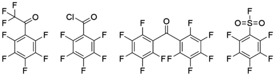 | ||
| Fig. 3 Used perfluoroaromatic compounds: perfluoroacetophenone (PSUa), pentafluorobenzoylchloride (PSUc), perfluorobenzophenone (PSUb), pentafluorbenzensulfonylfluoride (PSUs). | ||
To yield an ion-conducting polymer, it is necessary to introduce an ion-conducting group to the modified PSU polymers. This work aimed to synthesize a polymeric membrane material for potential use in high-temperature electrochemical applications. Subsequently, the para-fluoro atoms were phosphonated by nucleophilic aromatic substitution by reaction with tris(trimethylsilyl)phosphite to attain a proton-conducting polymer after hydrolysis of the silyl ester.21 This reaction is shown exemplarily in Fig. 4 for PSUa. Afterward, the synthesized materials were fully characterized by NMR-spectroscopy, TGA, DSC, GPC, and acid–base titration.
 | ||
| Fig. 4 Exemplary Michaelis–Arbuzov reaction scheme with PSUa to obtain p-PSUa. | ||
Materials and methods
Materials
Polysulfone Udel® (supplier: Solvay S. A.) or PSU Ultrason S® (producer: BASF SE), respectively, was used as received. Tris(trimethylsilyl)phosphite, perfluoroacetophenone, perfluorobenzophenone, pentafluorobenzoylchloride, and pentafluorobenzenesulfonyl fluoride were purchased at Manchester Organics. n-Butyllithium (2.5 M in Hexanes), THF (dry, 250 ppm Butylhydroxytoluene as inhibitor), heptane, and other solvents were purchased at Sigma Aldrich. All chemicals were used without further purification steps. The glassware was cleaned and air-dried prior to use. All syntheses were carried out under an argon atmosphere.Instruments, polymer, and membrane characterization
The chemical composition and structure of starting materials and products were characterized by proton, fluorine, and phosphorus NMR-spectroscopy. The 1H, 19F, and 31P-spectra were recorded at room temperature by a 500 MHz JEOL ECX-400 NMR spectrometer.The molecular weight distribution for the non-phosphonated reaction products of lithiated PSU with different perfluoroaromatic compounds and the phosphonated PSU derivatives (Mn, PDI) was determined using gel permeation chromatography (GPC). In our study, a GPC system SECurity2 from PSS Polymer Standard Service Mainz, Germany, equipped with a UV and refractive index detector, was used. The chromatography was done with a PSS SDV LUX GUARD, a PSS SDV LUX 3 µm 1000 Å, and a PSS SDV LUX 3 µm 10![[thin space (1/6-em)]](https://www.rsc.org/images/entities/char_2009.gif) 000 Å column set, which were calibrated with a series of polystyrene standards in THF. The respective polymer was dissolved in non-stabilized THF with a concentration of 1g L−1 for the measurement itself. The polymer solution was filtered using a syringe filter over a microporous PTFE membrane (0.45 µm), injected, and separated over the columns with a 1 mL min−1 flow rate.
000 Å column set, which were calibrated with a series of polystyrene standards in THF. The respective polymer was dissolved in non-stabilized THF with a concentration of 1g L−1 for the measurement itself. The polymer solution was filtered using a syringe filter over a microporous PTFE membrane (0.45 µm), injected, and separated over the columns with a 1 mL min−1 flow rate.
The thermal stability of the synthesized polymers was determined by TGA measurements. For that purpose, a TGA 800 instrument from PerkinElmer was used. The decomposition measurements were performed with a heating rate of 10 K min−1 under a synthetic air (SA) atmosphere, starting from room temperature to 900 °C.
To determine the glass transition temperature (Tg) of the synthesized polymers, a DSC 3+ device from Mettler Toledo was used. The sample was heated and cooled down in two cycles, starting from room temperature up to 300 °C with a heating/cooling rate of 20 K min−1.
The ion exchange capacities (IECs) were determined by acid–base titration with an OMNIS Titrator from Metrohm. For the titration itself, the polymers/membranes in H+ form were stirred in a warm, saturated sodium chloride solution to exchange the protons for sodium cations. The released H+ ions were titrated with a 0.1 M sodium hydroxide solution to the equivalent point to determine IECdirect.
 | (1) |
Then, a defined volume of 0.1 M sodium hydroxide solution was added. Afterwards, the solution was back titrated with 0.1 M HCl to determine IECtotal.
 | (2) |
The polymer's/membrane's ionic conductivity was measured by impedance spectroscopy with a Zennium X workstation from Zahner, Kronach, Germany. The measurements were done at room temperature in 0.5 M sulphuric acid to minimize contact resistances according to a method described by Kerres et al.50
The samples’ water uptake was determined at 85 °C. The samples were dried in an oven and weighed in a dry state (mdry). Afterward, the samples were placed in a vial with water, which was heated for 48 hours at 85 °C. Then, the samples were taken out of the water, quickly wiped dry, and weighed in the wet state (mwet). The water uptake was calculated based on the two determined values according to the following equation.
 | (3) |
The samples’ swelling in water was determined at 85 °C. The samples were dried in an oven, and their thickness was measured in a dry state (ddry). Subsequently, the samples were placed in a vial with water, which was heated for 48 hours at 85 °C. Then the samples were taken out of the water, quickly wiped dry, and the thickness was measured in the wet state (dwet). According to the following equation, the swelling ratio was calculated based on the two determined values.
 | (4) |
The chemical stability, particularly against radicals, was investigated by storing the samples in Fenton's reagent (4 ppm Fe2+, 3% H2O2) at 85 °C for 48 h. The samples were weighed before and after the test to determine a potential loss in mass.
By using a Thermo Fisher Scientific Talos F200i equipped with a high-angle annular dark field (HAADF) STEM detector, images of a blend membrane were recorded. The microscope features a Schottky emitter and was operated at an acceleration voltage of 200 kV. Data analysis was carried out using the Velox software.
Polymer modification syntheses
The starting material, polysulfone (PSU), was entirely dissolved in dry THF under an Argon atmosphere at room temperature and cooled down to −78 °C. n-Buthyllithium (n-BuLi) was added to the solution until all water traces were removed, indicated by a reddish colouring. In the second step, two equivalents of n-BuLi per repeating unit PSU were added to the solution, while its colour turned red.33 After one hour, the respective electrophilic compound (perfluoroacetophenone, perfluorobenzophenone, pentafluorobenzoylchloride, or pentafluorobenzenesulfonylfluoride) was added in molar excess (6 mol of carbonyl per PSU repeating unit). The solution was left stirring at −78 °C until it was homogenized, and then the cooling bath was slowly warmed to room temperature overnight by switching off the thermostat. Subsequently, the polymer was precipitated in methanol and washed with methanol. Finally, the obtained colorless solid was dried under a vacuum.For the phosphonation according to Atanasov and Kerres,21 the beforehand modified PSU (PSUa, PSUb, PSUc, or PSUs) was dissolved in pure tris(trimethylsilyl)phosphite and heated up to 160–170 °C under argon atmosphere for several hours. Complete dissolution of the polymer was only obtained at elevated temperatures. If not already precipitated after cooling down, the polymer was precipitated and washed in n-heptane.
To remove the silyl esters, the polymer was heated up to reflux in water overnight. After that, the raw product was treated with 1 M HCl for 24 hours at elevated temperature to acidify the phosphonic acid and hydrolyze the intermediate possible remaining silyl ester groups to the H+-form of the phosphonic acids (fully protonated form, PO3H2-group). Finally, the obtained polymer was dried.
Membrane preparation
For application and measuring conductivity, the polymers were cast as blended membranes. The phosphonated polysulfones (p-PSUa, p-PSUb, and p-PSUs) and the second blend component (a phosphonated terphenyl polymer from p-terphenyl and perfluoroacetophenone synthesized by polyhydroxyalkylation and subsequent Michaelis–Arbuzov phosphonation)51 were dissolved separately in the same solvent and subsequently mixed until a homogeneous mixture was obtained. Afterward, the blend solution was cast onto a glass plate, doctor-bladed, heated to 80 °C, and then the solvent was evaporated in a convection oven. To ensure complete protonation, the membranes were post-treated by immersing them in 10 wt% sulphuric acid at 85 °C for 96 h and washing several times with water at 85 °C until a constant water pH-value of 7 was reached.Results and discussion
Modification of PSU with pentafluorophenyl group containing side chains
 | (5) |
 | ||
| Fig. 5 1H NMR spectra of substituted PSUs. (a) Unmodified PSU, (b) PSUa, (c) PSUb, (d) PSUc, (e) PSUs, measured in THF-d8 at room temperature. | ||
The degrees of substitution, experimentally determined and calculated by 1H NMR spectroscopy for the four different used perfluoroaromatic-modified PSU polymers are summarized in Table 1. In comparison, the DOS for PSUa, PSUb, and PSUc are in the same range. However, the DOS for PSUs is markedly lower.
| PSUa | PSUb | PSUc | PSUs | |
|---|---|---|---|---|
| DOS in % | 80 | 88 | 77 | 58 |
For the substitution reaction of lithiated PSU with pentafluorophenyl compounds, a maximum of two side groups per repeating unit is theoretically possible, resulting in a DOS of 100% (two side chains per repeating unit). A higher theoretical DOS is impossible because the two aromatic rings pendent to the sulfone bridge of the PSU repeating unit become deactivated after the first carbanion per aromatic ring has formed by deprotonation with n-BuLi. However, a DOS of one could not be reached in reality for one or more of the following reasons: depending on the introduced pentafluorophenyl compound, the polymer can run into a solubility issue during the substitution reaction. When fluorinated side groups start to become attached to the backbone, the solubility of the polymer in the solvent decreases significantly, or, in other words, the polymer begins to precipitate during the substitution reaction, which prevents complete substitution. This issue was particularly observed at the formation of PSUs (reaction of lithiated PSU with pentafluorophenylsulfonyl fluoride). Furthermore, there is some sterical hindrance after the first side group has been added to the polymer repeating unit. As a consequence, the substitution with a second side group is less probable.
The successful introduction of a perfluoroaromatic side chain was further verified by 19F NMR spectroscopy (Fig. 6). The pentafluorophenyl side chains cause a characteristic substitution pattern of the F substituents, resulting in three signals with an integral ratio of 2:1:2, corresponding to the ortho, para, and meta positions of the fluorine atoms in the pentafluorophenyl moiety. These three characteristic signals show a chemical shift between −130 ppm and −170 ppm. In case there is a CF3 group remaining after the substitution reaction (see the conversion of PSU to PSUa), these fluorine atoms are detected at a chemical shift of −73 ppm. However, the DOS cannot be determined from the 19F NMR spectra because there is no fluorine in the unmodified PSU as a reference. It is only possible to check by 1H NMR whether the substitution reaction was successful.
 | ||
| Fig. 6 19F NMR spectra of the four substituted PSU derivates: PSUa (a), PSUb (b), PSUc (c), PSUs (d), measured in THF-d8 at room temperature. | ||
:1 ratio. This characteristic substitution pattern was obtained for all three soluble modified PSU compounds: p-PSUa, p-PSUb, and p-PSUs. This showed the successful quantitative phosphonation of all pentafluorophenyl-containing side chains. The respective 19F NMR spectra are shown in Fig. 7.
 | ||
| Fig. 7 19F-NMR spectra of p-PSUa (a), p-PSUb (b) and p-PSUs (c), measured in DMSO-d6 at room temperature. | ||
Furthermore, the success of the phosphonation reaction was verified by 31P NMR measurements. Spectra were only obtained for p-PSUa, p-PSUb, and p-PSUs, due to the solubility issues of p-PSUc. Fig. 8 shows the 31P NMR spectrum of p-PSUa as an example. The spectra of p-PSUb and p-PSUs are depicted in the ESI (Fig. S1 and S2†). Within the shown spectra, only a single signal at −2.9 ppm was detected, which is characteristic of the P of the phosphonic acid group. This also confirms the successful phosphonation of PSUa to p-PSUa. PSUb and PSUs were phosphonated successfully as well, yielding p-PSUb and p-PSUs.
 | ||
| Fig. 8 31P NMR spectrum of p-PSUa, measured in DMSO-d6 at room temperature. | ||
To investigate the influence of the introduced phosphonated side chains on the glass transition temperature Tg, the second DSC heating curve of virgin PSU was compared to those of the substituted PSUs. The second curve was used because water and solvent residuals were removed during the first heating and cooling cycle. The DSC curves of PSU and the phosphonated PSUs are depicted in the following Fig. 9.
 | ||
| Fig. 9 DSC-traces (2nd heating cycle) of PSU, p-PSUa, p-PSUb, p-PSUc and p-PSUs. | ||
From the DSC trace of virgin PSU, a Tg of 189 °C was determined, which is comparable to the literature.35 In case large aromatic perfluorinated and phosphonated sidechains are attached to the polymeric backbone, an increasing glass transition temperature is expected for the modified polymers. In this study, the Tg for p-PSUa was determined at 215 °C and for p-PSUs at 230 °C, which proves the expected trend. The Tg of p-PSUb and p-PSUc are in the same temperature range. In summary, all four phosphonated polymers show a glass transition temperature higher than unmodified PSU (189 °C). This increase in the glass transition temperature is caused by the bulky side chains introduced to virgin PSU. The introduced aromatic rings in the side chain lead to a higher rigidity of the chains, which causes their higher glass transition temperatures.
Also, introducing phosphonic acid groups leads to an increase in the Tg since the acidic groups create a hydrogen bridge network within the macromolecular chains, which contributes to the Tg increase. For sulfonated PSU membranes, an increasing Tg, compared to unmodified PSU, has also been observed.52
Especially in the polymers’ potential field of application, their thermal stability is highly important. Therefore, the thermal stability of the phosphonated synthesized materials was investigated by TGA. To be able to compare the TGA results with those of other studies, standard conditions were used (heating rate of 10 K min−1). From the literature, it is well known that commercial PSU is stable up to 500 °C. Their thermal stability is in the same range regardless of whether they are exposed to air or to a nitrogen atmosphere.35,45,52 In the following Fig. 10(a), the TGA traces of the phosphonated polymers are shown in comparison to virgin PSU. In Fig. 10(b), the TGA curves of unmodified PSU, PSUb, and p-PSUb are shown in comparison.
 | ||
| Fig. 10 (a) TGA curves of PSU, p-PSUc, p-PSUb, p-PSUs and p-PSUa under synthetic air, with a heating rate of 10 K min−1. (b) TGA curves of PSU, PSUb and p-PSUb under synthetic air, with a heating rate of 10 K min−. | ||
In comparison, all phosphonated polymers show a first decrease in mass of up to 100 °C, caused by remaining water residues in the polymer samples. For a sulfonated PSU derivative, a similar behaviour was observed by Karlsson et al.45 A second decrease in mass between 2.7% and 5.0% was observed between 100 °C and 320 °C. The first mass losses in this range were caused by the release of hydration water from the phosphonic acid groups. Beginning at 200 °C, the attached phosphonic acid groups typically start forming anhydrides after the elimination of water. In a study presented by Lafitte and Jannasch, the formation of phosphonic acid anhydrides is shown for directly phosphonated PSU in a temperature range between 200 °C and 320 °C.35 Bock et al. show that for a PSU membrane, which is phosphonated in its backbone, similar behaviour is observed below 325 °C.53 This is also caused by the formation of phosphonic acid anhydrides.53 In a recent study by Atanasov et al., the energy barriers for the formation of different types of phosphonic acid anhydrides, e.g., methyl phosphonic acid, phosphoric acid, and pentafluorophenylphosphonic acid, were discussed.32 This study showed the onset of the anhydride formation at 240 °C for a pentafluorophenyl phosphonic acid.32 For the PSU derivatives containing tetrafluorophenylphosphonic acid groups synthesized in this study, similar behaviour is expected. The fact that the anhydride formation of these polymeric phosphonic acids takes place only at T > 200 °C makes these ionomers potential candidates for the application as electrode ionomers in HTPEMFCs, as for the related perfluoroaromatic phosphonated ionomer poly(2,3,5,6-tetrafluoro-4-phosphonic acid) the suitability for use as electrode ionomer in HTPEMFCs up to temperatures of 200 °C could be shown in the aforementioned recent study.32 Beginning at a temperature of 350 °C, a decomposition of the polymers’ backbones is observed. Similar behaviour was already reported for various phosphonated PSUs or PPSU.35,45,49,53–55
In Fig. 10(b), the unmodified PSU's degradation begins beyond 500 °C in a two-step degradation mechanism. In case different substituents are added to the polymer's backbone, as shown for PSUb, the beginning of the degradation was already observed at a temperature of 350 °C. In the case of the PSUb's phosphonated analogue, the evaporation of water residues and hydration water in the polymer sample was observed. Above 200 °C, the onset of formation of phosphonic acid anhydrides was observed. After that, the degradation of p-PSUb started at 350 °C, which is the same temperature range as that of PSUb.
| PSU | PSUa | p-PSUa | |
|---|---|---|---|
| M repeating unit in g mol−1 | 442 | 970 | 1094 |
| M n in g mol−1 | 43800 |
38700 |
44600 |
| M w in g mol−1 | 73300 |
78000 |
69800 |
| Đ | 1.67 | 2.01 | 1.56 |
The determined molecular weights were in the same range. However, the molar mass per repeating unit doubled due to the introduced side chains, which led to an apparent lower polymerization degree. On the other hand, due to the performed modification reactions, the chemical structure of the molecules became significantly changed. Adding fluorinated compounds to the polymer backbone significantly changed its polarity and hydrophilicity. This led to a different gyration radius of the polymer in solution, causing different retention times in the chromatography columns and, therefore, different (apparent) molecular weights compared to unmodified PSU. To assess a loss in molecular weight by the modification reactions, the polydispersity index (PDI) was used. Before PSU was lithiated, the dispersity was 1.67; afterward, the polydispersity increased to 2.01. The slightly increasing PDI strongly indicates partial degradation of the backbone caused by the lithiation step. The polydispersity of the phosphonated polymer amounts to 1.56, which is lower than the PDI of PSUa (see Table 2). The phosphonation step caused this change in dispersity because the phosphonated polymer fragments with a low molecular weight became water-soluble and were washed out. For PSUb, PSUc, and PSUs, a similar trend for the polymers’ dispersity was observed after adding the fluorinated compound. In total, a slight decrease in molecular weight was observed for all four modified polymers. However, the increasing dispersity and decreasing Mn do not influence further reactions and polymer properties.
 | (6) |
 | (7) |
The theoretical and experimentally determined values for the IECdirect and IECtotal are listed in the following Table 3.
| Polymer | Calculated | Titrated | ||
|---|---|---|---|---|
| IECdirect in mmol g−1 | IECtotal in mmol g−1 | IECdirect in mmol g−1 | IECtotal in mmol g−1 | |
| p-PSUa | 1.46 | 2.92 | 1.90 | 3.45 |
| p-PSUb | 2.44 | 4.87 | 2.21 | 4.53 |
| p-PSUc | 1.56 | 3.13 | 0.33 | 0.68 |
| p-PSUs | 1.10 | 2.20 | 1.04 | 1.65 |
For the three phosphonated materials, p-PSUa, p-PSUb, and p-PSUs, the experimental IECs are in the same range as the theoretical ones. However, they differ slightly from the theoretical IECs, which could be caused by a differing DOS compared to the DOS determined by NMR. Furthermore, for p-PSUb and p-PSUs, an incomplete phosphonation is conceivable.
The experimental values for p-PSUc differ significantly from the theoretical ones. This strongly supports the hypothesis that the phosphonation reaction of PSUc was incomplete due to the previously discussed solubility issues.
| DMSO | DMAc | Isopropanol | THF | |
|---|---|---|---|---|
| PSU | n | s | n | s |
| p-PSUa | s | s | s | s |
| p-PSUb | (s) | (s) | n | n |
| p-PSUc | n | n | n | n |
| p-PSUs | (s) | n | n | n |
Acid-acid blend membranes
Membranes from solely (highly) phosphonated polysulfones often show bad mechanical properties, as they tend to be brittle.35 This makes them unsuitable for application as a membrane in electrochemical processes such as fuel cells, electrolysers, and redox-flow batteries. Therefore, the synthesized polymers were cast as blend membranes together with a polymer with good film-forming and good mechanical properties. In this work, we selected another phosphonated polymer for blending, in the following named as Ter-Phos.51 Thereby, almost no functionality is lost through blending, as would be the case, e.g., in acid–base blends, due to electrostatic interactions of the acid group with a base (protonation of the base/ionic cross-linking between the phosphonate anion and the protonated base cation).5 This blend polymer is prepared by a polyhydroxyalkalation reaction of perfluoroacetophenone with p-terphenyl, followed by a phosphonation reaction using the same phosphonation method as shown before.51 In the ESI Fig. S11† shows the synthesis route of Ter-Phos. It was synthesized in our lab and showed good film-forming properties, high solubility, and good conductivity. Polymers of this type have been prepared recently by Kang et al.51 However, this polymer (Ter-Phos) suffers from high water uptake and swelling, thus hindering its application as a membrane for fuel cells, electrolysers, or redox flow batteries, as too high swelling might lead to the blocking of pore systems and mechanical pressure building up inside a cell during operation.56 Blend membranes from this terphenyl polymer and our soluble phosphonated polysulfones (p-PSUa, p-PSUb, and p-PSUs) were prepared with a polymer weight ratio of 1:1. Despite the relatively low solubility of p-PSUb and p-PSUs, the blended membranes were readily castable. Photographs of the prepared membranes are shown in Fig. 11.
 | ||
| Fig. 11 Photographs of three different blend membranes with Ter-Phos (a) p-PSUa:Ter-Phos, 1:1; (b) p-PSUb:Ter-Phos, 1:1; (c) p-PSUs:Ter-Phos, 1:1. | ||
All obtained membranes were transparent, suggesting interactions (e.g., hydrogen bridges) and, therefore, good miscibility between the dissolved polymers can be concluded. A reddish and yellowish colour can be seen for the pPSU-b and the p-PSUs blend, respectively, caused by the different colours of the p-PSU polymers.
The polymer blend membranes were investigated in terms of water uptake, conductivity, ion exchange capacity, and stability against radicals using Fenton's test. The characterization results are shown in Table 5 and discussed below. The values for a membrane consisting of pure phosphonated terphenyl are also included in Table 5 for comparison.
| IECtotal,theo [mmol g−1] | IECdir [mmol g−1] | IECtot [mmol g−1] | Thickness [µm] | Water uptake [%] | Swelling [%] | Wt-loss Fenton's [%] | Conductivity σ [mS cm−1] | |
|---|---|---|---|---|---|---|---|---|
| p-PSUa | 3.32 | 3.19 | 5.08 | 30 | 23 | 8 | 3 | 76 |
| p-PSUb | 4.29 | 1.98 | 5.23 | 30 | 0 | 0 | 11 | 154 |
| p-PSUs | 2.96 | 1.47 | 2.50 | 9 | 3 | 0 | 0 | 46 |
| Ter-Phos | 1.86 | 2.04 | 2.28 | 48 | 25 | 45 | — | 29 |
The number of phosphonic acid groups attached per repetition unit follows the order p-PSUb > p-PSUa > p-PSUs. Perfluorobenzophenone is the only perfluoroaromatic compound with two pentafluorophenyl groups, which allows more phosphonic acid groups to be attached. At the same time, the p-PSUa and p-PSUs precursors have only one pentafluorophenyl moiety per side chain and, therefore, fewer sites for the subsequent phosponation reaction. Thus, the absolute number depends on the DOS, which is lower for p-PSUs compared to p-PSUa as shown previously in Table 1. Measured and calculated IEC values reflect this order. The measured conductivity correlates with the IEC and is highest for the p-PSUb blend.
All the blend membranes show sufficient ionic conductivity. As can be seen, the pure phosphonated terphenyl membrane also shows sufficient conductivity. However, all prepared blend membranes show higher conductivities at room temperature combined with lower swelling. Particularly remarkable is the p-PSUb blend with conductivity higher than 150 mS cm−1, which hardly swells and takes up water, even after being immersed in water at 85 °C for several days.
We were able to produce mechanically stable membranes from polymers with a high phosphonation degree that maintain their high conductivity after blending and hardly swell in contact with water. The latter especially distinguishes them from other highly conductive phosphonated polysulfones, which potentially increases their applicability in electrochemical processes. Additionally, the stability against radicals determined by Fenton's test is relatively high for the blended phosphonated membranes. Only the membrane from p-PSUb suffers from a weight loss of eleven weight percent, which is comparable to other blended phosphonated membranes. E.g., Atanasov et al. report a seven-weight percent loss for their blended phosphonated PPFS (polypentafluorostyrene) and OOPBI membrane.57 Our results, therefore, support the trend observed in the literature that blended membranes show higher stabilities than their pure counterpart due to the interactions between the functional groups of the blend components.58–61
Conclusions
Within this study, a new group of PSU derivatives was synthesized. We were able to introduce four different side chains containing pentafluorophenyl moieties (perfluoroacetophenone, perfluorobenzophenone, pentafluorobenzoylchloride, pentafluorobenzenesulfonyl fluoride) to the polymer backbone. However, due to reactivity issues, sterical hindrance, and solubility issues of the substituted PSUs, we were able to introduce maximally up to two side chains per repeating unit (DOS ≈ 1). It could be shown that 1H NMR spectroscopy is a suitable method for determining the degree of substitution of the polymer materials presented in this study. The substitution reactions led to materials with a high thermal stability of up to 350 °C.Furthermore, three of the four materials (PSUa, PSUb, and PSUc) were successfully phosphonated. These polymer materials show a high thermal stability (up to 350 °C). However, they start forming phosphonic acid anhydrides above 200 °C, limiting their potential temperature range for applications such as fuel cells and electrolyzers. In addition, the phosphonated polymers have high ion exchange capacities between 1.65 mmol g−1 and 4.53 mmol g−1, connected with sufficient solubility in polar solvents. In summary, these novel phosphonic acid groups containing materials are promising candidates for membranes and/or electrode ionomers in electrochemical applications such as (HT)-PEMFCs, (HT)-PEMWEs, or redox flow batteries.
First blend membranes prepared from this new class of polymers show promising conductivity and mechanical properties for application in electrochemical cells.
In ongoing work, we investigate further substitution reactions of the pentafluorophenyl group-modified PSU polymers to improve their properties in terms of proton conductivity, solubility, mechanical and thermal stability. Among the possible substitution reactions are nucleophilic substitution reactions of the F atoms of the pentafluorophenyl side chains. This opens new avenues for novel functional, high-performance polymers based on PSU.
Author contributions
Philipp Martschin: conceptualization, methodology, resources, investigation, data curation, visualization, project administration, writing – original draft. Timo Prölß: investigation, data curation, visualization, writing – review and editing. Andreas Hutzler: investigation, data curation, visualization, writing – review and editing. Simon Thiele: writing – review and editing, supervision, funding acquisition. Jochen Kerres: conceptualization, methodology, resources, writing – review and editing, project administration, supervision.Data availability
The data supporting this article have been included as part of the ESI.†Conflicts of interest
There are no conflicts to declare.Acknowledgements
We acknowledge funding from the Bavarian Ministry of Economic Affairs, Regional Development and Energy, grant number 44-6665a2/132/1, and the Federal Ministry of Education and Research, grant number 03HY108A.We gratefully acknowledge the help of Annika Schmuker, Xenia Lang, and Dominik Sämann in the characterization of the polymers and membranes presented in this study. Furthermore, we acknowledge the help of Dr Thomas Böhm for ultramicrotomy.
References
- M. Carmo, D. L. Fritz, J. Mergel and D. Stolten, Int. J. Hydrogen Energy, 2013, 38, 4901 CrossRef CAS.
- Y. Wang, D. F. Ruiz Diaz, K. S. Chen, Z. Wang and X. C. Adroher, Mater. Today, 2020, 32, 178 CrossRef CAS.
- S. Auffarth, W. Dafinger, J. Mehler, V. Ardizzon, P. Preuster, P. Wasserscheid, S. Thiele and J. Kerres, J. Mater. Chem. A, 2022, 10, 17208 RSC.
- O. Savadogo, ChemInform, 1998, 29(47) DOI:10.1002/chin.199847334.
- J. A. Kerres, Fuel Cells, 2005, 5, 230 CrossRef CAS.
- P. Xing, G. P. Robertson, M. D. Guiver, S. D. Mikhailenko, K. Wang and S. Kaliaguine, J. Membr. Sci., 2004, 229, 95 CrossRef CAS.
- J. A. Kerres, Polym. Rev., 2015, 55, 273 CrossRef CAS.
- R. P. O'Hayre, S.-W. Cha, W. G. Colella and F. B. Prinz, Fuel cell fundamentals, John Wiley & Sons Inc, Hoboken, New Jersey, 2016 Search PubMed.
- F. Arslan, T. Böhm, J. Kerres and S. Thiele, J. Membr. Sci., 2021, 625, 119145 CrossRef CAS.
- Z. Wang, A. M. Buser, I. T. Cousins, S. Demattio, W. Drost, O. Johansson, K. Ohno, G. Patlewicz, A. M. Richard, G. W. Walker, G. S. White and E. Leinala, Environ. Sci. Technol., 2021, 55, 15575 CrossRef CAS.
- H. Brunn, G. Arnold, W. Körner, G. Rippen, K. G. Steinhäuser and I. Valentin, Environ. Sci. Eur., 2023, 35(20) DOI:10.1186/s12302-023-00721-8.
- J. Miyake, R. Taki, T. Mochizuki, R. Shimizu, R. Akiyama, M. Uchida and K. Miyatake, Sci. Adv., 2017, 3, eaao0476 CrossRef PubMed.
- N. R. Kang, T. H. Pham and P. Jannasch, ACS Macro Lett., 2019, 8, 1247 CrossRef CAS PubMed.
- Z. Long, J. Miyake and K. Miyatake, ACS Appl. Energy Mater., 2019, 2, 7527 CrossRef CAS.
- M. Adamski, N. Peressin and S. Holdcroft, Mater. Adv., 2021, 2, 4966 RSC.
- M. K. Pagels, S. Adhikari, R. C. Walgama, A. Singh, J. Han, D. Shin and C. Bae, ACS Macro Lett., 2020, 9, 1489 CrossRef CAS.
- J. A. Kerres, D. Xing and F. Schönberger, J. Polym. Sci., Part B:Polym. Phys., 2006, 44, 2311 CrossRef CAS.
- M. Schuster, K.-D. Kreuer, H. T. Andersen and J. Maier, Macromolecules, 2007, 40, 598 CrossRef CAS.
- P. Martschin, V. Atanasov, S. Thiele and J. Kerres, ACS Polym. Au, 2024, 4, 492–497 CrossRef CAS PubMed.
- J. Chen, L. Dumas, J. Duchet-Rumeau, E. Fleury, A. Charlot and D. Portinha, J. Polym. Sci., Part A:Polym. Chem., 2012, 50, 3452 CrossRef CAS.
- V. Atanasov and J. Kerres, Macromolecules, 2011, 44, 6416 CrossRef CAS.
- V. Atanasov, M. Bürger, S. Lyonnard, L. Porcar and J. Kerres, Solid State Ionics, 2013, 252, 75 CrossRef CAS.
- J.-M. Noy, Y. Li, W. Smolan and P. J. Roth, Macromolecules, 2019, 52, 3083 CrossRef CAS.
- G. Sych, J. Simokaitiene, R. Lygaitis, E. Jatautiene, R. Pashazadeh, G. Buika and J. V. Grazulevicius, React. Funct. Polym., 2019, 143, 104323 CrossRef CAS.
- H. Cho, V. Atanasov, H. M. Krieg and J. A. Kerres, Polymers, 2020, 12, 915 CrossRef CAS PubMed.
- C. D. Murphy, B. R. Clark and J. Amadio, Appl. Microbiol. Biotechnol., 2009, 84, 617 CrossRef CAS PubMed.
- B. Lafitte and P. Jannasch, in Advances in Fuel Cell, Elsevier, 2007, vol. 1, p. 119 Search PubMed.
- D. J. Jones and J. Rozière, J. Membr. Sci., 2001, 185, 41 CrossRef CAS.
- Fundamentals and performance of low temperature fuel cells, ed. C. Hartning and C. Roth, Woodhead Pub, Oxford, 2012 Search PubMed.
- High Temperature Polymer Electrolyte Membrane Fuel Cells: Approaches, Status, and Perspectives, ed. Q. Li, D. Aili, H. A. Hjuler and J. O. Jensen, Springer, Cham, 2016 Search PubMed.
- C. Vogel and J. Meier-Haack, Desalination, 2014, 342, 156 CrossRef CAS.
- V. Atanasov, A. S. Lee, E. J. Park, S. Maurya, E. D. Baca, C. Fujimoto, M. Hibbs, I. Matanovic, J. Kerres and Y. S. Kim, Nat. Mater., 2021, 20, 370 CrossRef CAS PubMed.
- M. D. Guiver, J. W. Apsimon and O. Kutowy, J. Polym. Sci., Part C: Polym. Lett., 1988, 26, 123 CrossRef CAS.
- V. L. Rao, J. Macromol. Sci., Part C: Polym. Rev., 1999, 39, 655 CrossRef.
- B. Lafitte and P. Jannasch, J. Polym. Sci., Part A:Polym. Chem., 2005, 43, 273 CrossRef CAS.
- Fuel Cells II, ed. G. G. Scherer, Springer Berlin Heidelberg, Berlin, Heidelberg, 2008 Search PubMed.
- P. Zschocke and D. Quellmalz, J. Membr. Sci., 1985, 22, 325 CrossRef CAS.
- P. Jannasch, Fuel Cells, 2005, 5, 248 CrossRef CAS.
- M. D. Guiver, S. Croteau, J. D. Hazlett and O. Kutowy, Br. Polym. J., 1990, 23, 29 Search PubMed.
- M. D. Guiver, P. Black, C. M. Tam and Y. Deslandes, J. Appl. Polym. Sci., 1993, 48, 1597 CrossRef CAS.
- J. Kerres, W. Cui and S. Reichle, J. Polym. Sci., Part A:Polym. Chem., 1996, 34, 2421 CrossRef CAS.
- Membrane formation and modification, ed. I. Pinnau, American Chemical Society, Washington, DC, 2000 Search PubMed.
- J. Kerres, A. Ullrich and M. Hein, J. Polym. Sci., Part A:Polym. Chem., 2001, 39, 2874 CrossRef CAS.
- B. Lafitte, L. E. Karlsson and P. Jannasch, Macromol. Rapid Commun., 2002, 23, 896 CrossRef CAS.
- L. E. Karlsson and P. Jannasch, Electrochim. Acta, 2005, 50, 1939 CrossRef CAS.
- J. C. Persson, K. Josefsson and P. Jannasch, Polymer, 2006, 47, 991 CrossRef CAS.
- B. Lafitte, M. Puchner and P. Jannasch, Macromol. Rapid Commun., 2005, 26, 1464 CrossRef CAS.
- J. Parvole and P. Jannasch, J. Mater. Chem., 2008, 18, 5547 RSC.
- J. Parvole and P. Jannasch, Macromolecules, 2008, 41, 3893 CrossRef CAS.
- J. Kerres, A. Ullrich, T. Häring, M. Baldauf, U. Gebhardt and W. Preidel, J. New Mater. Electrochem. Syst., 2000, 3, 229–239 CAS.
- N. R. Kang, T. H. Pham, H. Nederstedt and P. Jannasch, J. Membr. Sci., 2021, 623, 119074 CrossRef CAS.
- F. Lufrano, G. Squadrito, A. Patti and E. Passalacqua, J. Appl. Polym. Sci., 2000, 77, 1250 CrossRef CAS.
- T. Bock, R. Mülhaupt and H. Möhwald, Macromol. Rapid Commun., 2006, 27, 2065 CrossRef CAS.
- N. Y. Abu-Thabit, S. A. Ali and S. M. Javaid Zaidi, J. Membr. Sci., 2010, 360, 26 CrossRef CAS.
- H. Tang, K. Geng, Y. Hu and N. Li, J. Membr. Sci., 2020, 605, 118107 CrossRef CAS.
- Y. Zhou, G. Lin, A. J. Shih and S. J. Hu, J. Power Sources, 2009, 192, 544 CrossRef CAS.
- V. Atanasov, D. Gudat, B. Ruffmann and J. Kerres, Eur. Polym. J., 2013, 49, 3977 CrossRef CAS.
- J. Kerres and V. Atanasov, Int. J. Hydrogen Energy, 2015, 40, 14723 CrossRef CAS.
- E. Bülbül, V. Atanasov, M. Mehlhorn, M. Bürger, A. Chromik, T. Häring and J. Kerres, J. Membr. Sci., 2019, 570–571, 194 CrossRef.
- J. Kerres, F. Schönberger, A. Chromik, T. Häring, Q. Li, J. O. Jensen, C. Pan, P. Noyé and N. J. Bjerrum, Fuel Cells, 2008, 8, 175 CrossRef CAS.
- D. Yazili, E. Marini, T. Saatkamp, A. Münchinger, T. de Wild, L. Gubler, G. Titvinidze, M. Schuster, C. Schare, L. Jörissen and K.-D. Kreuer, J. Power Sources, 2023, 563, 232791 CrossRef CAS.
Footnote |
| † Electronic supplementary information (ESI) available: Additional characterization data of synthesised polymers. See DOI: https://doi.org/10.1039/d4py01289e |
| This journal is © The Royal Society of Chemistry 2025 |