
 Open Access Article
 This Open Access Article is licensed under a
 Creative Commons Attribution 3.0 Unported Licence
Microwave-assisted synthesis of mesoporous high-entropy alloy and core–shell nanoparticles†
Chuyi
Ni
 ,
Suni
Guo
,
Cole
Butler
and
Jonathan G. C.
Veinot
*
,
Suni
Guo
,
Cole
Butler
and
Jonathan G. C.
Veinot
*
Department of Chemistry, University of Alberta, Edmonton, Alberta, Canada T6G 2G2. E-mail: jveinot@ualberta.ca
First published on 4th February 2025
Abstract
Mesoporous high-entropy alloy nanoparticles (mp-HEA NPs) are an emerging class of nanostructured materials that bring together the distinctive solid-solution structure and multi-element compositions of their non-porous counterparts and highly accessible surfaces that characterize mesoporous materials. In this study, we present the facile synthesis of mp-HEA NPs (RhAgCuPdPt) via microwave-assisted heating. The structural, compositional, and morphological characteristics of the mp-HEA NPs were assessed using Brunauer–Emmett–Teller (BET) surface area analysis, X-ray diffraction (XRD), Fourier-transform infrared spectroscopy (FTIR), X-ray photoelectron spectroscopy (XPS) and transmission electron microscopy (TEM). We subsequently extended our approach to realize mesoporous Au core-HEA (RhAgCuPdPt) shell NPs (Au-HEA NPs) and investigated the thermal conversion of the Au-HEA NP to HEA NPs (AuRhAgCuPdPt) using in situ heating TEM. We determined that this conversion involves gradual grain growth at temperatures below 600 °C followed by a rapid grain growth process at elevated temperatures accompanied by the collapse of the mesostructure.
Introduction
High-entropy alloy nanoparticles (HEA NPs) have emerged as a captivating new class of materials.1,2 These nanomaterials possess multi-elemental compositions and distinctive high-entropy solid-solution structures that provide access to exquisitely tunable reactivity and stability.3 A variety of methods have been presented that provide access to HEA NPs including “carbo-thermal shock”,4 vapor phase spark discharge, rapid radiative heating or annealing, low-temperature hydrogen spillover, microwave heating and the colloidal method.5–13Porous metallic materials bearing high surface areas and tunable pore structures constitute an important class of nanomaterials.14 Classical mesoporous metal alloy nanoparticles prepared using wet-chemical reduction methods predominantly comprise two or three metal elements.15,16 Expanding the number of constituent metal elements to five (or more) in these systems presents a significant challenge presumably because of the diverse physicochemical properties and differences in Ered of the metals.17 The Liu group reported a hard template-assisted synthesis of mesoporous HEA NPs. They used KIT-6 as template and synthesized PtPdFeCoNi HEA NPs inside the ordered mesopores, following by HF etching to provide mesoporous HEA NPs with an ordered polyhedral morphology.18 The Faustini group introduced a straightforward route to synthesize ordered macro- and mesoporous PtPdRuRdIr HEA NPs with uniform pore size and high surface area that relies on spray-drying aqueous solutions comprising five different noble metal precursors onto polymer latex beads.19 The polymer latex template was decomposed via thermal annealing under Ar, resulting in the formation of ordered porous HEA NPs. An alternative approach presented by the Yamauchi group used “one-pot” wet-chemical reduction to synthesize mesoporous PtPdRhRuCu HEA NPs using a diblock polymer as a soft template.20 These mesoporous nanoparticles exhibited a core–shell structure with a Pd-rich core and Rh/Ru-rich shell that was attributed to the differences in reduction order during the prolonged heating.
Using microwave heating in nanomaterial preparation has become increasingly popular.21 Its attractive attributes, include rapid heating that minimizes of temperature gradients, accelerate reaction rates and facilitates HEA NP synthesis.9 Herein, we present a microwave-assisted heating procedure for preparing mesoporous HEA NPs (RhAgCuPdPt) with the aim of reducing the reaction time and minimizing the formation of a core–shell structure. Using this method, we successfully synthesized mesoporous HEA NPs (RhAgCuPdPt) by using F127 and L-ascorbic acid (L-AA) as pore-directing and reducing agents, respectively. With these promising results in hand, we explored predictably introducing an Au while targeting the synthesis of mesoporous Au core-HEA shell NPs (Au-HEA NPs). Moreover, we delved into the thermal conversion of Au-HEA NPs to HEA NPs (AuRhAgCuPdPt) using in situ heating transmission electron microscopy. The experimental observations revealed that at elevated temperatures (i.e., 300 °C), the high-entropy components began to diffuse into the Au. Initially, this process is slow, but the rate of the diffusion increases at temperatures exceeding 600 °C.
Synthesis of mesoporous HEA NPs (RhAgCuPdPt)
The synthesis of mesoporous HEA NPs (RhAgCuPdPt) was achieved using an adaptation of a microwave heating method previously employed to prepare bimetallic and trimetallic mesoporous particles (Scheme 1).22 Formation of F127 micelles was induced by adding aqueous HCl and water to a F127/DMF solution (Experimental section). Subsequently, the micelle suspension was combined with an aqueous solution containing equimolar concentrations of the desired metal salts (i.e., RhCl3, AgNO3, CuCl2, PdCl2, PtCl4) and the mixture was heated in a laboratory microwave reactor to 130 °C for 1 min. | ||
| Scheme 1 A pictorial illustration of the formation of mesoporous high-entropy alloy nanoparticles (HEA NPs: RhAgCuPdPt) via microwave heating. An aqueous solution containing metal salts (i.e., RhCl3, AgNO3, CuCl2, PdCl2, and PtCl4) was added into the solution of F127 solution, followed by adding L-AA. The solution was then microwave heated to 130 °C for 1 min. Mesoporous HEA NPs were obtained following the removal of the template with acetone. | ||
Powder X-ray diffraction (XRD) was used to examine the crystal structure of mesoporous HEA NPs (RhAgCuPdPt). The XRD pattern (Fig. S1a†) indicates the mesoporous HEA NPs display a characteristic face-centred cubic structure as evidenced by (111), (200), (220) and (311) reflections appearing at 39.5°, 45.7°, 66.7° and 80.3°, respectively. Those reflections are consistent with the reference determined using Vegard's Law when considering the elemental compositions obtained from EDX (Fig. S1a†). No reflections arising from the individual metals were observed consistent with the formation of a single-phase alloy structure without phase segregation. The broadening of HEA NPs reflections was analyzed using the Scherrer equation and provided an estimated crystallite size of 84 ± 3 nm.23 After considering the dependence of reflection broadening on diffraction angle, the broadening distribution of mesoporous HEA NPs (RhAgCuPdPt) (Fig. S1b†) shows that there is also strain-induced broadening.24 Small-angle X-ray scattering (SAXS) (Fig. S1c†) afforded a broad peak at 0.22° that provided a pore-to-pore spacing of 18.5 nm in the present mesoporous HEA NPs (RhAgCuPdPt).
The surface area and pore structure of mesoporous HEA NPs (RhAgCuPdPt) were evaluated using N2 adsorption–desorption. The resulting isotherms (Fig. S2a†) were characteristic of Type-IV materials with a hysteresis loop, which represents the capillary condensation and indicated the existence of mesopores.25 In addition, the BET surface area was found to be 18.968 m2 g−1 and is comparable with previously reported multimetallic mesoporous PdPtCu NPs.22 The pore size distribution curve (Fig. S2b†) derived from adsorption branches using density functional theory (DFT) method also suggest that the sample possessed pores size of 6.8 nm.
To further investigate the nature of mesoporous HEA NPs (RhAgCuPdPt), we probed the materials using Fourier-transform infrared (FTIR) and X-ray photoelectron spectroscopy (XPS). Before removal of the soft template the FTIR spectrum (Fig. S3†) of the mesoporous HEA NPs (RhAgCuPdPt) exhibited prominent features attributed to the F127. Following removal of the micelles, the FTIR spectrum of the resulting mesoporous HEA NPs (RhAgCuPdPt) displayed no discernible features consistent with complete removal of the F127 at the sensitivity of the FTIR method.
XPS provides additional insight into the material composition, bonding environment, and oxidation states of elements in the present materials. The survey XP spectrum of mesoporous HEA NPs (RhAgCuPdPt) revealed evidence of corresponding metal emissions (Fig. S4†). Integrating the emission peaks in the survey XPS spectra allowed quantification of the elemental compositions of mesoporous HEA NPs (RhAgCuPdPt). The calculated atomic percentages for each metal were approximately 20 atomic %, indicating a near equal molar composition (Table S1†). The high-resolution XP spectra of mesoporous HEA NPs (RhAgCuPdPt) revealed emissions associated with the corresponding metals (Rh, Ag, Cu, Pd, and Pt) (Fig. S5†). The XP spectra of each metal showed emissions with binding energies characteristic of their corresponding metallic state (i.e., Rh 3d5/2, 307.4 eV; Ag 3d5/2, 368.0 eV; Cu 2p3/2, 932.1 eV; Pd 3d5/2, 335.1 eV; Pt 4f7/2, 71.0 eV).
Electron microscopy techniques were employed to investigate the morphology of mesoporous HEA NPs (RhAgCuPdPt). Secondary electron scanning transmission electron microscopy (SE-STEM) imaging (Fig. 1a and S6a†) and high-angle annular dark-field scanning transmission electron microscopy (HAADF-STEM) imaging (Fig. 1b) confirmed the formation of mesoporous spherical HEA NPs with dimensions 88 ± 16 nm (Fig. S6b†) and uniformly sized mesopores 10 nm (Fig. S6a†). High resolution transmission electron microscopy (HRTEM) images showed lattice fringes with interplanar crystal spacings of 0.22 nm corresponding to the (111) plane of fcc HEA NPs (RhAgCuPdPt) (Fig. S6c†). EDX mapping confirmed the co-localization (Fig. 1c–h) and uniform elemental distribution of all metal, as confirmed by line-profile analysis (Fig. S6d†). We attribute this uniform distribution to the rapid heating during the microwave synthesis that facilitates the co-reduction of all the metal constituents.9 The EDX spectrum (Fig. S7†) showed all five target metals (i.e., ca. 5 atom %) signals. Collectively, these findings, in combination with XRD and XPS, support the conclusion that the present mesoporous HEA NPs (RhAgCuPdPt) are homogeneous.
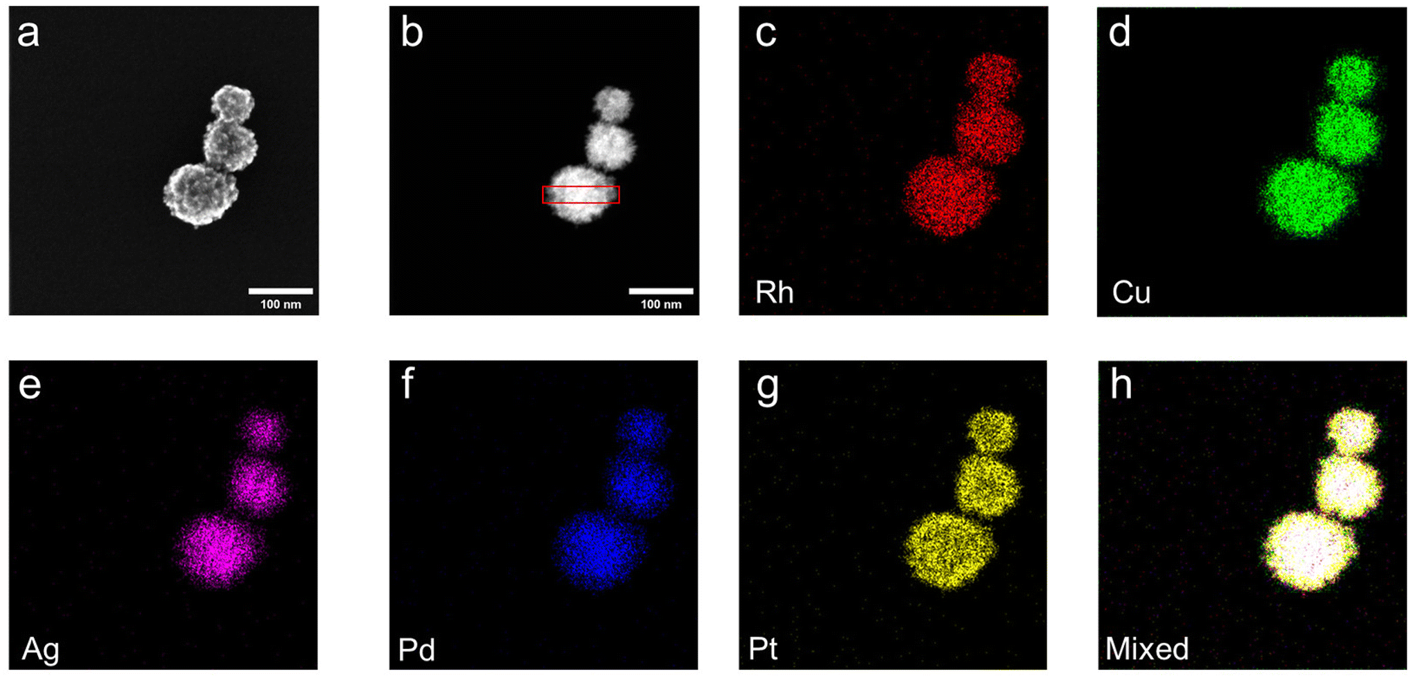 | ||
| Fig. 1 TEM and EDX analyses of mesoporous HEA NPs (RhAgCuPdPt). (a) SE-STEM image, (b) HAADF-STEM image and (c–h) corresponding EDX mapping of the indicated elements and mixed mapping. | ||
Synthesis of mesoporous Au core-HEA (RhAgCuPdPt) shell NPs
Having demonstrated the microwave heating affords mesoporous HEA NPs, we explored the incorporation of Au core into the mesoporous HEA NPs (Scheme S1†). While previous noble metals were only reduced by L-AA with the assistance of microwave, the direct reduction of Au by L-AA facilitates formation of the Au core for the subsequent preparation of the mesoporous Au core-HEA (RhAgCuPdPt) shell NPs (Au-HEA NPs). To address this, we synthesized mesoporous Au-HEA NPs by initially mixing F127 micelles with a solution comprising metal salts (i.e., AuCl3, RhCl3, AgNO3, CuCl2, PdCl2, PtCl4) followed by the addition of L-AA solution. Contrary to our previous observations for systems lacking a gold precursor, the reaction mixture immediately turned black (Fig. S8a and b†). TEM imaging (Fig. S8c†) showed the presence of only Au nanoparticles suggesting Au ions were reduced first. Subsequent microwave heating led to the formation of the mesoporous HEA NPs shell.The crystal structure and bonding of mesoporous Au-HEA NPs were investigated through XRD and FTIR spectroscopy. XRD analysis (Fig. S9a†) showed characteristic reflections consistent with the mesoporous HEA NPs (39.5°, 45.7°, 66.7° and 80.3°). In addition, reflections corresponding to Au core were observed at slightly lower angles (38.1°, 44.3°, 64.5°, 77.6°). Scherrer analyses provided an estimate of the HEA shell crystallite size of 89 ± 6 nm and Au core size around 142 ± 9 nm. The broadening distribution of the HEA shell indicated a strain-induced broadening, while the broadening distribution of the Au core indicated a size-induced broadening (Fig. S9b†). A SAXS pattern (Fig. S9c†) showed a peak at 0.23° that corresponds to a pore-to-pore distance of 17.6 nm. In the FTIR spectrum of the mesoporous Au-HEA NPs before washing (Fig. S10†), the characteristic features of F127 were observed. After purification, the FTIR spectrum showed no substantial features related to F127, suggesting complete removal of the soft template.
To investigate the surface area and pore structure, mesoporous Au-HEA NPs were also examined by N2 adsorption–desorption experiments. A typical Type-IV isotherm with a hysteresis loop (Fig. S11a†) were observed for the sample suggesting the existence of mesopores.25 A comparatively lower BET surface area were calculated as 8.597 m2 g−1 relative to mesoporous HEA NPs, presumably because of the presence of the Au core. The pore size distribution curve (Fig. S11b†) suggests that samples possessed a mesopore size of 6.8 nm.
XPS was used to investigate the elemental composition and oxidation states of resulting mesoporous Au-HEA NPs. The survey spectrum (Fig. S12†) showed the expected metal emissions from the HEA NPs (approximately 14 atomic %). There is no Au emission observed due to the limit of XPS probing depth, consistent with the incorporation of the Au core inside HEA NPs. The high-resolution spectra of each metal exhibited characteristic metallic state (Fig. S13†), including Rh 3d5/2, 307.5 eV; Ag 3d5/2, 368.0 eV; Cu 2p3/2, 932.0 eV; Pd 3d5/2, 335.1 eV; Pt 4f7/2, 71.0 eV.
SE-STEM and HAADF-STEM images (Fig. 2a and b) confirmed the formation of mesoporous Au-HEA NPs and its dimensions were measured to be 238 ± 26 nm with Au core size of 145 ± 21 nm (Fig. S14a and b†). The size of the outer HEA shell is approximately 93 nm which was consistent with the estimate provided by XRD. EDX mapping provided evidence of the co-localization of morphological features for Au core and HEA NPs shell in HAADF-STEM image and confirmed the presence of the five target metals (Rh, Ag, Cu, Pd, Pt), as confirmed by the line profile results (Fig. S14c†). The Au shell and Pt core signals were falsely mapped due to the overlapping of Au and Pt Mα/Mβ signals (Fig. S15†). The EDX spectrum (Fig. S15†) further indicated an elemental composition of Rh (1.6 atom %), Ag (1.5 atom %), Cu (1.3 atom %), Pd (1.1 atom %) and Pt (1.4 atom %) with higher Au concentration from the core (6.4 atom %).
 | ||
| Fig. 2 TEM and EDX analysis of mesoporous Au-HEA NPs. (a) SE-STEM image, (b) HAADF-STEM image and (c–h) corresponding EDX mapping of the indicated elements. | ||
In situ transformation of mesoporous Au-HEA NPs to HEA NPs
Drawing inspiration from the conversion of two-phase core–shell NPs into single-phase HEA NPs by thermal annealing,13,26 we have explored the transformation of mesoporous Au-HEA NPs to HEA NPs via in situ heating STEM and presented in Movie S1.† The SE- and HAADF-STEM images of the same location (Fig. 3 and S16†) captured the morphological changes of mesoporous Au-HEA NPs as they were heated from room temperature to 800 °C, leading to the formation of HEA NPs. There was no observed change observed below 300 °C. Above 300 °C, metal atoms diffused into the Au core accompanying with the shrinkage of the mesopores. Notably, the Au core gets larger slowly below 600 °C, but grows rapidly at 600 °C and above, resulting in the complete collapse of the mesoporous structure. EDX mapping (Fig. S17†) further confirmed presence of the Au core and mesoporous HEA NPs shell before heating. Post-heating EDX mapping (Fig. S18†) is consistent with the formation of HEA NPs (AuRhAgCuPdPt). Line profile analysis further confirms the conversion of core–shell NPs to single phase system (Fig. S19†). The EDX spectrum (Fig. S20†) showed the signals corresponding to Au and the other five metal signals remained around 3 atomic % after heating. This finding suggests the transformation from mesoporous Au-HEA NPs to HEA NPs (AuRhAgCuPdPt).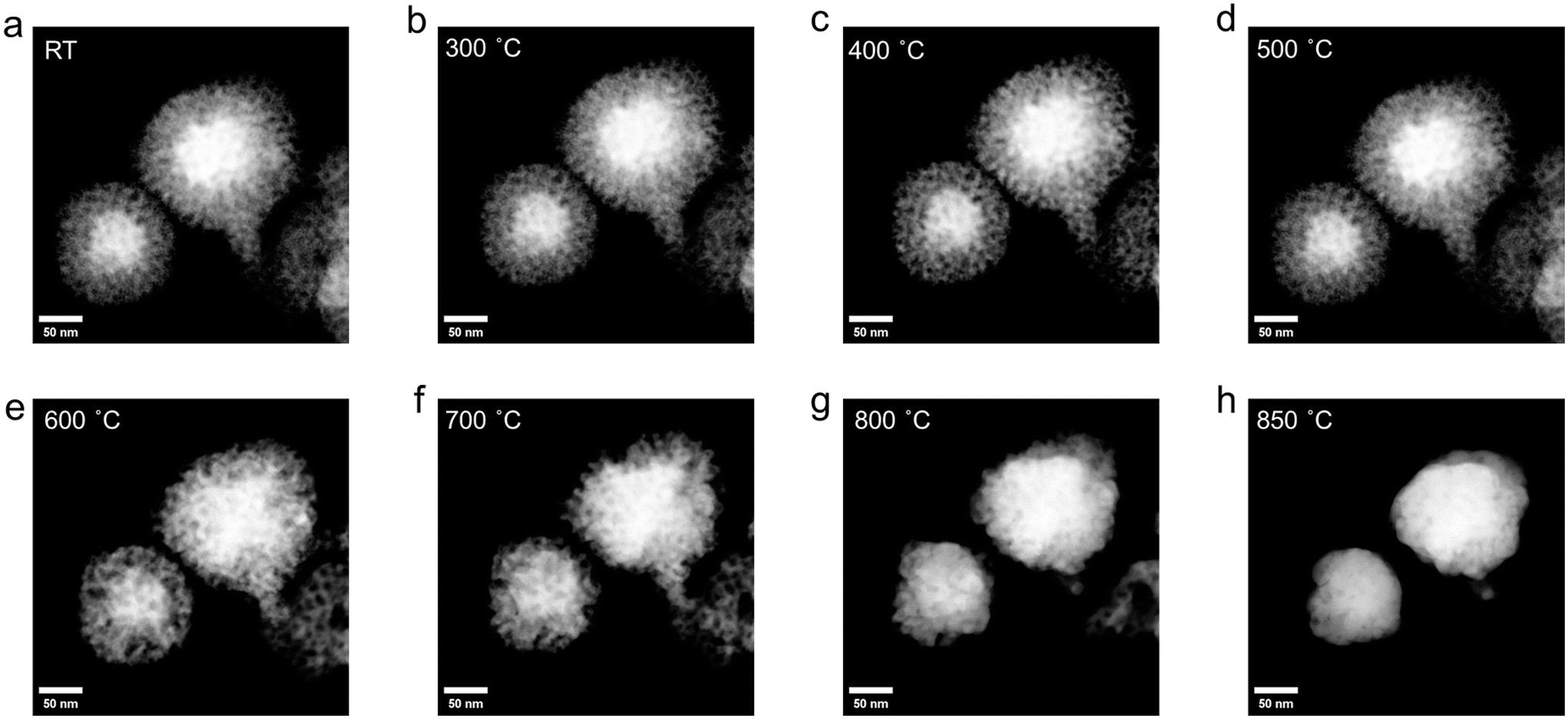 | ||
| Fig. 3 HAADF-STEM images of mesoporous Au-HEA NPs at the same location during the in situ heating experiment from room temperature to 850 °C (a–h). The sample slightly shifted due to the thermal drift. | ||
Conclusions
The present study has demonstrated a straightforward method for preparing mesoporous high-entropy alloy nanoparticles (HEA NPs: RhAgCuPdPt) via microwave-assisted heating. The synthesis of the mesoporous HEA NPs was verified by X-ray diffraction (XRD) and X-ray photoelectron spectroscopy (XPS), which provided evidence of the desired elements and their oxidation states. The mesoporous structure of the HEA NPs was confirmed by s small-angle X-ray scattering (SAXS) and N2 adsorption–desorption experiments. Transmission electron microscopy (TEM) analysis further revealed that the HEA NPs possessed a mesoporous structure and exhibited a homogenous distribution of the metal elements throughout the material. This method can be extended to synthesize mesoporous Au core-HEA shell NPs (Au-HEA NPs). We further investigated the thermal conversion of the mesoporous Au-HEA NPs (RhAgCuPdPt) to HEA NPs (AuRhAgCuPdPt) by in situ heating STEM. The conversion involved a slow Au core growth process through atom diffusion at temperatures below 600 °C, and finally a rapid grain growth process with the collapse of the mesopores at higher temperatures.Experimental
Materials
L-Ascorbic acid (L-AA, 99.99%), gold chloride (AuCl3, 99.99%), silver nitrate (AgNO3, 99.9999%), copper chloride (CuCl2, 99.999%), palladium chloride (PdCl2, 99.9%), rhodium chloride (RhCl2·xH2O, 98%), platinum chloride (PtCl4, 99.999%) and Pluorinc F127 were purchased from Sigma-Aldrich and hydrochloric acid (HCl, 37% w/w), ethanol (anhydrous), acetone (HPLC grade) and N,N-dimethylformamide (DMF, HPLC grade) were purchased from Fisher Scientific. Milli-Q (18.2 MΩ cm at 25 °C) water was used for all experiments. All organic solvents were dried using an Innovative Technology, Inc. Grubbs-type solvent purification system.![[thin space (1/6-em)]](https://www.rsc.org/images/entities/char_2009.gif) :1) for three times. The product was dried for 12 h in vacuo and subsequently characterized using XRD, XPS, and TEM. Typical mass yields for this procedure were 10 mg.
:1) for three times. The product was dried for 12 h in vacuo and subsequently characterized using XRD, XPS, and TEM. Typical mass yields for this procedure were 10 mg.
:1) for three times. The product was dried for 12 h in vacuo and subsequently characterized using XRD, XPS, and TEM. Typical mass yields for this procedure were 10 mg.
:1) for three times. The product was dried for 12 h in vacuo and subsequently characterized using XRD, XPS, and TEM. Typical mass yields for this procedure were 10 mg.
Characterization
In situ heating TEM experiments were conducted using the DENSsolutions Wildfire in situ heating TEM sample holder. TEM samples were prepared by depositing a drop (5 μL) of a dilute ethanol suspension of metal salts and GeNSs onto a DENSsolutions Wildfire Si3N4 nano-chip. The heating program was monitored by DENSsolutions Impulse software. After collecting the images and EDX mapping at room temperature, the samples were heated up to 800 °C at 1 °C s−1 and kept at 800 °C for 10 min. Then the samples were cooled down to room temperature at 20 °C s−1.
Author contributions
Chuyi Ni: conceptualization, methodology, investigation, formal analysis, investigation, data curation, and writing – original draft. Suni Guo: investigation, data acquisition, and writing, review and editing. Cole Butler: investigation, data acquisition, and writing, review and editing. Jonathan G. C. Veinot: supervision, conceptualization, methodology, formal analysis, investigation, funding acquisition, and writing, review and editing. All authors discussed the results and the implications of this manuscript. All authors have given approval to the final version of the manuscript.Data availability
The data supporting this article have been included as part of the ESI.†Conflicts of interest
There are no conflicts to declare.Acknowledgements
The authors recognize the continued generous funding from the Natural Science and Engineering Research Council (NSERC Discovery Grant program; RGPIN-2020-04045), the ATUMS training program supported by NSERC CREATE (CREATE-463990-2015) as well as the University of Alberta Faculties of Science and Graduate Studies, and Alberta Innovates Strategic Projects Program. C.N. acknowledges support from Alberta Innovates in the form of an Alberta Innovates Graduate Scholarship. We also thank the staff at Analytical and Instrumentation Laboratory in the Department of Chemistry at the University of Alberta for the assistance with FTIR analysis, and the University of Alberta Nanofab for support in collecting XPS data.References
- Y. Yao, Q. Dong, A. Brozena, J. Luo, J. Miao, M. Chi, C. Wang, I. G. Kevrekidis, Z. J. Ren, J. Greeley, G. Wang, A. Anapolsky and L. Hu, Science, 2022, 376, abn3103 CrossRef PubMed.
- H. Lv and B. Liu, Chem. Soc. Rev., 2024, 53, 11321–11333 RSC.
- M. W. Glasscott, A. D. Pendergast, S. Goines, A. R. Bishop, A. T. Hoang, C. Renault and J. E. Dick, Nat. Commun., 2019, 10, 2650 CrossRef PubMed.
- Y. Yao, Z. Huang, P. Xie, S. D. Lacey, R. J. Jacob, H. Xie, F. Chen, A. Nie, T. Pu, M. Rehwoldt, D. Yu, M. R. Zachariah, C. Wang, R. Shahbazian-Yassar, J. Li and L. Hu, Science, 2018, 359, 1489–1494 CrossRef CAS PubMed.
- P.-C. Chen, X. Liu, J. L. Hedrick, Z. Xie, S. Wang, Q.-Y. Lin, M. C. Hersam, V. P. Dravid and C. A. Mirkin, Science, 2016, 352, 1565–1569 CrossRef CAS PubMed.
- N. Kumar, C. S. Tiwary and K. Biswas, J. Mater. Sci., 2018, 53, 13411–13423 CrossRef CAS.
- S. Gao, S. Hao, Z. Huang, Y. Yuan, S. Han, L. Lei, X. Zhang, R. Shahbazian-Yassar and J. Lu, Nat. Commun., 2020, 11, 2016 CrossRef CAS.
- K. Mori, N. Hashimoto, N. Kamiuchi, H. Yoshida, H. Kobayashi and H. Yamashita, Nat. Commun., 2021, 12, 3884 CrossRef CAS.
- H. Qiao, M. T. Saray, X. Wang, S. Xu, G. Chen, Z. Huang, C. Chen, G. Zhong, Q. Dong, M. Hong, H. Xie, R. Shahbazian-Yassar and L. Hu, ACS Nano, 2021, 15, 14928–14937 CrossRef CAS.
- G. Zhu, Y. Jiang, H. Yang, H. Wang, Y. Fang, L. Wang, M. Xie, P. Qiu and W. Luo, Adv. Mater., 2022, 34, e2110128 CrossRef.
- G. Cao, J. Liang, Z. Guo, K. Yang, G. Wang, H. Wang, X. Wan, Z. Li, Y. Bai, Y. Zhang, J. Liu, Y. Feng, Z. Zheng, C. Lu, G. He, Z. Xiong, Z. Liu, S. Chen, Y. Guo, M. Zeng, J. Lin and L. Fu, Nature, 2023, 619, 73–77 CrossRef CAS PubMed.
- N. Hashimoto, K. Mori and H. Yamashita, J. Phys. Chem. C, 2023, 127, 20786–20793 CrossRef CAS.
- N. Kar, M. McCoy, J. Wolfe, S. L. A. Bueno, I. H. Shafei and S. E. Skrabalak, Nat. Synth., 2024, 3, 175–184 CrossRef CAS.
- Y. Zou, X. Zhou, J. Ma, X. Yang and Y. Deng, Chem. Soc. Rev., 2020, 49, 1173–1208 RSC.
- J. Fang, L. Zhang, J. Li, L. Lu, C. Ma, S. Cheng, Z. Li, Q. Xiong and H. You, Nat. Commun., 2018, 9, 521 CrossRef.
- Y. Kang, B. Jiang, Z. A. Alothman, A. Y. Badjah, M. Naushad, M. Habila, S. Wabaidur, J. Henzie, H. Li and Y. Yamauchi, Chemistry, 2019, 25, 343–348 CrossRef CAS.
- B. Jiang, C. Li, O. Dag, H. Abe, T. Takei, T. Imai, M. S. A. Hossain, M. T. Islam, K. Wood, J. Henzie and Y. Yamauchi, Nat. Commun., 2017, 8, 15581 CrossRef CAS.
- Y. Wang, X. Y. Zhang, H. He, J. J. Chen and B. Liu, Adv. Energy Mater., 2024, 14, 2303923 CrossRef CAS.
- M. L. De Marco, W. Baaziz, S. Sharna, F. Devred, C. Poleunis, A. Chevillot-Biraud, S. Nowak, R. Haddad, M. Odziomek, C. Boissiere, D. P. Debecker, O. Ersen, J. Peron and M. Faustini, ACS Nano, 2022, 16, 15837–15849 CrossRef CAS.
- Y. Kang, O. Cretu, J. Kikkawa, K. Kimoto, H. Nara, A. S. Nugraha, H. Kawamoto, M. Eguchi, T. Liao, Z. Sun, T. Asahi and Y. Yamauchi, Nat. Commun., 2023, 14, 4182 CrossRef CAS.
- T. M. Atkins, A. Thibert, D. S. Larsen, S. Dey, N. D. Browning and S. M. Kauzlarich, J. Am. Chem. Soc., 2011, 133, 20664–20667 CrossRef CAS PubMed.
- B. Jiang, C. Li, M. Imura, J. Tang and Y. Yamauchi, Adv. Sci., 2015, 2, 1500112 CrossRef.
- U. Holzwarth and N. Gibson, Nat. Nanotechnol., 2011, 6, 534–534 CrossRef CAS.
- C. Ni, K. M. O'Connor, J. Trach, C. Butler, B. Rieger and J. G. C. Veinot, Nanoscale Horiz., 2023, 8, 1217–1225 RSC.
- M. Kruk and M. Jaroniec, Chem. Mater., 2001, 13, 3169–3183 CrossRef CAS.
- S. L. A. Bueno, A. Leonardi, N. Kar, K. Chatterjee, X. Zhan, C. Chen, Z. Wang, M. Engel, V. Fung and S. E. Skrabalak, ACS Nano, 2022, 16, 18873–18885 CrossRef CAS PubMed.
- S. L. Anderson, E. J. Luber, B. C. Olsen and J. M. Buriak, Chem. Mater., 2016, 28, 5973–5975 CrossRef CAS.
- H. Yu, A. N. Thiessen, M. A. Hossain, M. J. Kloberg, B. Rieger and J. G. C. Veinot, Chem. Mater., 2020, 32, 4536–4543 CrossRef CAS.
- Y. Zhang, X. Han, R. Liu, Y. Liu, H. Huang, J. Zhang, H. Yu and Z. Kang, J. Phys. Chem. C, 2012, 116, 20363–20367 CrossRef CAS.
- L. Ma, L. Jia, X. Guo and L. Xiang, Chin. J. Catal., 2014, 35, 108–119 CrossRef CAS.
- M. C. Biesinger, Surf. Interface Anal., 2017, 49, 1325–1334 CrossRef CAS.
- M. C. Militello and S. J. Simko, Surf. Sci. Spectra, 1994, 3, 387–394 CrossRef CAS.
- C. R. O'Connor, M. A. Van Spronsen, M. Karatok, J. Boscoboinik, C. M. Friend and M. M. Montemore, J. Phys. Chem. C, 2021, 125, 10685–10692 CrossRef.
- G. Silversmit, D. Depla, H. Poelman, G. B. Marin and R. De Gryse, J. Electron Spectrosc. Relat. Phenom., 2004, 135, 167–175 CrossRef CAS.
Footnote |
| † Electronic supplementary information (ESI) available. See DOI: https://doi.org/10.1039/d4nr05019c |
| This journal is © The Royal Society of Chemistry 2025 |