
 Open Access Article
 This Open Access Article is licensed under a Creative Commons Attribution-Non Commercial 3.0 Unported Licence
Elaboration of hollow mesoporous organosilica nanospheres of various sizes†
Manisa
Kongkaew
c,
Imane
El Moujarrad
ab,
Rozenn
Le Parc
 a,
Paul
Mohammadi
a,
Magali
Gary-Bobo
e,
Carole
Carcel
c,
Guillaume
Toquer
d,
Philippe
Trens
c,
David
Maurin
a,
Erwan
Oliviero
c,
Philippe
Dieudonné
a,
Makoto
Ogawa
f,
Jean-Louis
Bantignies
a and
Michel Wong Chi
Man
*c
a,
Paul
Mohammadi
a,
Magali
Gary-Bobo
e,
Carole
Carcel
c,
Guillaume
Toquer
d,
Philippe
Trens
c,
David
Maurin
a,
Erwan
Oliviero
c,
Philippe
Dieudonné
a,
Makoto
Ogawa
f,
Jean-Louis
Bantignies
a and
Michel Wong Chi
Man
*c
aLaboratoire Charles Coulomb, UMR CNRS 5221, University of Montpellier, Montpellier, France
bPhantom-g, CICECO–Aveiro Institute of Materials, Department of Physics, University of Aveiro, Aveiro, 3810-193, Portugal
cICGM, Univ Montpellier, CNRS, ENSCM, Montpellier, France. E-mail: michel.wong-chi-man@umontpellier.Fr
dICSM, Univ Montpellier, CEA, CNRS, ENSCM, Marcoule, France
eIBMM, Univ Montpellier, CNRS, ENSCM, Montpellier, France
fSchool of Energy Science and Engineering (ESE), Vidyasirimedhi Institute of Science and Technology (VISTEC), Wangchan Valley, Rayong, Thailand
First published on 15th May 2025
Abstract
Hollow mesoporous organosilica (HMO) nanoparticles with a controlled core cavity and a mesoporous organosilica shell are elaborated using coupled hard and soft templating approaches. A dense silica hard template is first synthesized following the classical Stöber sol–gel protocol. The hybrid silica shell is then deposited through the co-condensation of an organosilane precursor with surfactant. HMO-NPs are obtained after the removal of the hard and soft templates. In this study, we demonstrate that this strategy can be applied to synthesize HMO-NPs of different sizes. We present a multiscale approach for a step-by-step characterization of synthesis stages, the structural organization of the PMO shell, and its properties. Particular emphasis is placed on the removal of the silica hard template step. A protocol is proposed to assess the efficiency of the etching process and estimate any remaining silica using infrared spectroscopy. Finally, from the perspective of potential medical applications, preliminary tests on endocytosis and biocompatibility are presented and yield promising results.
Introduction
Hollow mesoporous silica (HMS) materials are characterized by a hollow core–shell architecture, with porous walls that provide a high surface area for the efficient encapsulation and release of guest molecules. Such porosity facilitates a high loading capacity and offers a large surface for chemical reactions, making HMS an attractive candidate for various applications, including drug delivery,1–4 contrast agent carriers,5,6 environmental remediation,7,8 and catalysis.9The synthesis of hollow mesoporous silica (HMS) typically involves template-assisted methods, in which a template material, such as a sacrificial hard or soft template, is used to form the hollow structure.10,11 Although one-step synthesis based on a soft template has been reported,12 the most common approach is the hard template method, where a silica shell is deposited on the surface of a core material (polymer microspheres by instance), followed by the removal of the core through chemical etching or thermal treatment to create the hollow cavity.
The use of organosilane precursors instead of TEOS presents the versatility of these materials toward alternative properties or better fine-tuning of material properties, such as surface reactivity and biocompatibility. To synthesize HMSN (hollow mesoporous silica NPs)/HMO NPs (hollow mesoporous organosilica NPs), the sol–gel method is used. Surfactant-free synthesis has been proposed.13 Nevertheless, in most studies, the synthesis of HMO NPs involves the direct co-assembly of organic–inorganic precursors, where the mesoporous silica framework is synthesized in the presence of surfactants, which can then be removed to leave behind a hybrid hollow structure with well-defined pores.14,15 The flexibility of this synthetic method allows for precise tuning of pore size, wall thickness, and surface functionality. However, challenges remain in achieving reproducibility and large-scale production, as well as in maintaining the structural integrity of hollow mesoporous structures.
In this study, we propose a protocol for the synthesis of HMO NPs from a BTEB (bis-trimethoxysilyl ethane) precursor, with sizes ranging from about 250 to 500 nm, using the templating method presented in a previous paper.16 We particularly focus on the optimization of the template removal step, which leads to hollow mesoporous spheres, whose efficiency varies for the different HMO sizes. We propose a protocol through easy lab control based on infrared (IR) spectroscopy to monitor the evolution of the amount of silica through different stages of the core etching process. The incorporation of fluorescent molecules within the final HMO will then be demonstrated as a proof of concept for further applications.
A-Coupled hard and soft templating strategy to synthesize HMO NPs with a phenylene-bridged precursor (BTEB-HMO)
The synthesis of BTEB-HMO follows a four-step strategy.Step 1: Synthesis of silica hard template
Spherical silica hard templates are synthesized following the Stöber sol–gel process17,18 with different sizes, adding different amounts of TEOS, water and NH4OH to control the hydrolysis/condensation rate. Ethanol, NH4OH and H2O are mixed under 750 rpm stirring; at a temperature of 30 °C, TEOS is added, and the reaction is left for 1 h. Table S1, in SI-1 (ESI†), summarizes the synthetic conditions for the different sizes of hard templates used in this study.
Step 2: Formation of BTEB-PMO shells around silica NPs
A strategy described in the literature19 is then used for the deposition of a hybrid mesoporous silica layer on the silica hard template. Water, ethanol, NH4OH and CTAB are added dropwise to the as-prepared suspension of silica NPs with a mean diameter of 436 nm obtained in step 1. After stirring the mixture, BTEB (0.2 mL) is added, and the reaction occurs under a gentle flow of argon for 6 h. The resulting HMO is named HMO-480-a.
Steps 3 and 4: Hard template etching and surfactant extraction
First, alkaline hot water etching is used for the silica core etching in Na2CO3 aqueous solution at 80 °C for 1h (HMO-480-b). The ions diffuse through the pores and dissolve the silica core to form water-soluble sodium silicate. Selective etching is then expected because the Si–C bonds in the organosilica shell are more chemically resistant to basic etching compared to the Si–O bonds of the core.13 After centrifugation/washing the hollow NPs twice with water and ethanol, the NPs are resuspended in ethanol solution with HCl under reflux at 80 °C overnight to remove the surfactant (CTAB), leading to the sample HMO-480-c showing a central cavity and empty mesopores.
Fig. 1 illustrates TEM images of objects formed after steps 2, 3 and 4. From hard templates with an average size of around 436 ± 40 nm obtained at step 1, the one-pot deposition of the hybrid mesoporous layer on these hard templates (step 2) results in particles with an external diameter around 480 ± 42 nm, which agrees with hydrodynamic diameter measurements from DLS experiments (see SI-5, ESI†). Owing to the slight electronic density contrast between the silica hard template and the hybrid shell, the shell thickness can be estimated at around 42 ± 10 nm. The silica hard template removal yields a TEM image with a strong contrast between the hollow core (light) and the shell (darker). Finally, after the last acidic treatment (step 4), the hollow nanoparticles retain a similar appearance to those observed at step 3. The slight change in the size distribution between pictures ii and iii is more representative of the broad size distribution (see SI-3, ESI†) and different sampling for the TEM image than of a change in size between steps 3 and 4.
 | ||
| Fig. 1 TEM images (scale 500 nm) of (i) the samples HMO-480-a, with an average diameter of 480 nm and a shell thickness of 42 nm, (ii) HMO-480-b, and (iii) HMO-480-c, with (iv) a zoomed image of HMO-480-c (scale 100 nm). | ||
Step 4, CTAB removal from the pores, is confirmed by IR spectroscopy (Fig. 2i) where the CH stretch in alkylene chains related to the CTAB, in the region 2800–2900 cm−1, disappears after the acidic treatment.
 | ||
| Fig. 2 (i) IR spectra in the region of CH stretching vibration. (ii) SAXS analyses performed on HMO-480 and (iii) nitrogen sorption relative to the three synthesis steps a, b, and c. (iv) BJH and DFT models applied to nitrogen adsorption for HPMO-480 a, b, and c. | ||
The porosity of the sample after the final step can be confirmed by nitrogen adsorption (Fig. 2iii). Nitrogen sorption analyses were performed at 77.35 K, and the isotherms gradually changed after steps 2, 3 and 4. After step 3, an increase in the sorption (specific surface equal to 284 m2 g−1) is observed; however, it remains limited because CTAB is still present in the pores of the material. The sorption measured is related to the external surface of the material. After CTAB extraction by acidic treatment (step 4), a significant increase in the sorption isotherm is shown in terms of the adsorbed amount and porosity. The final specific surfaces reach 1250 m2 g−1. The shape of this last sorption isotherm can be related to a type I/type IV mixture. The mesoporosity determined using the two models is estimated to be 2.7 nm (Fig. 2iv and Table 1). Larger porosities are associated with interparticular spaces.
| SSA m2 g−1 | Pore diameter (nm) | Pore volume (cm3 g−1) | |
|---|---|---|---|
| HPMO-480-a | 168 | 2.5 (DFT) | 0.060 |
| HPMO-480-b | 284 | 3.5; 6–11 (BJH) | 0.488 |
| HPMO-480-c | 1250 | 2.7; 3.9; 5–11 (BJH) | 1.190 |
The SAXS spectrum of HMO-480-a (Fig. 2i) exhibits two broad signals centered at 1.7 nm−1 and 3 nm−1. These corresponding planes (100) and (110) are assigned to a 2D hexagonal mesopore network (p6mm symmetry) with a lattice parameter a = 4 nm (a = 4π/√3/q0). Interestingly, after the silica hard template removal, the hexagonal lattice parameter clearly increases from 4 to 4.5 nm, and the signature is broader, suggesting some relaxation of the hybrid silica network. After CTAB removal (HMO-480-c), both signals appear much more intense because the electronic contrast increases once the pores are empty. The lattice parameter is also found to be equal to 4.5 nm.
Combining the lattice parameter found from SAXS and the mesoporosity from nitrogen adsorption, a quick estimation of the volume ratio of empty space in the mesoporous shell is found to be about 41% for HMO-480-a and 40% for HMO-480-c. Besides, the shell corresponds to 43% of the HMO volume. Therefore, the mesopores correspond to about 17% of the HMO total volume. Supposing that the density of silica is 2.2 g cm−3, bulk hybrid is 1.45 g cm−3 and CTAB is 0.5 g cm−3, sample HMO-480-a would be composed, in mass, by 76% of core, 19% of hybrid, and 5% of micelles, and sample HMO-480-b is ideally composed of 77% of hybrid and 23% of micelles.
To complete the investigation on the success of each synthesis step, IR spectroscopy was performed in the middle-IR domain (4000–400 cm−1) region. First, the silica hard template and mesoporous nanoparticles synthesized by sol gel from BTEB (so-called “phenylene-bridged silsesquioxane nanoparticles (Ph-BSQ-NPs)”) (details on the synthesis are given in the ESI†) are measured (Fig. 3i). The hard template exhibits characteristic silica features with strong asymmetric stretching νa (Si–O–Si) at 1101 cm−1 and rocking vibration groups δ (Si–O–Si) at 450 cm−1.20 The IR spectra of mesoporous nanoparticles synthesized by sol gel from BTEB (so-called Ph-BSQ-NPs) exhibit major differences. The main νa (Si–O–Si) band is still observed; however, its profile is strongly modified compared to the silica hard template. The feature appears much broader. The ν(Si–OH) feature observed at 950 cm−1 is slightly downshifted compared to the hard template, so symmetric stretching νs (Si–O–Si) is observed around 800 cm−1. A small peak appears on the massif at 1150 cm−1 that can be assigned to the Si–O–C stretching characteristic of hybrid silica. Another new feature appears for the hybrid around 523 cm−1 associated with aromatic ring out-of-plane deformation, which will be further used as a fingerprint of BTEB (peak 2). These results agree with previous work.16
 | ||
| Fig. 3 (i) MIR spectra of the hard template and of HMO-480 after the three synthesis steps a, b, and c compared with the MIR spectrum of a sample synthesized from BTEB without a hard template and without surfactant. (ii) Q-MAS NMR deconvolution for the samples corresponding to the three synthesis steps (a)–(c). For HMPO-480-b, Q2 and Q3 represent 55 and 45% of the total Qn species respectively, T2, T3 represent 35% and 65% of Tn species respectively. For HMPO-480-c, Q2 and Q3 represent 47% and 53% of the total Qn species, respectively while T2, T3 represent 42% and 51% of Tn species, respectively. | ||
The different steps of HMO-480 synthesis can then be analyzed (Fig. 3i). Just after the deposition of the hybrid layer on the silica hard template (HMO-480-a), aromatic ring deformation around 523 cm−1 (peak 2) appears, indicating the presence of the hybrid layer on the hard template. The sharp asymmetrical ν(Si–O–Si) band (peak 3) is still observed, exhibiting small broadening. However, it appears slightly redshifted. The rocking Si–O–Si band appears as intense as the hard template. After the hard template removal (HMO-480-b), further reduction in intensity for the Si–O–Si asymmetric stretch (peak 3) is observed in agreement with the removal of hard silica. One would expect the spectrum to be the same as the Ph-BSQ-NP one. However, the Si–O–Si rocking mode (peak 1) is still observed despite its decrease in intensity, which means that silica is still present in the sample. The alkaline etching has already been described as a reversible process.19 Therefore, the recondensation of silica is not excluded.21 The Raman spectra of HMO-480-a, b, c have also been measured (Fig. S11 in SI-8, ESI†). A distinctive Si–O–Si bending vibration signature is observed around 470 cm−1 for HMO-480-a but is hardly perceived for HMO-480-b and c. IR spectroscopy appears much more relevant for the detection of the residual silica.
Further insight is also available from Si NMR QMAS exploration, which indeed confirms that Qn species are still observed for HMO-480-b and -c, and therefore that hard silica has not been completely removed after alkaline treatment. The Qn/(Qn + Tn) massif ratios are found to be equal to 89, 69 and 74% for steps a, b, and c, respectively. Interestingly, some quantitative changes are observed in the Tn species after acidic treatment, with a decrease in the T3 species (from 0.65 to 0.51) and an increase in the T2 species (from 0.35 to 0.42), showing that the hybrid network is partially impacted by the chemical treatments.
B-Tuning the size of HMO NPs
HMO NPs are also synthetized with an intermediate size by varying the diameter of the hard template (see Table 1 and Fig. 4). Particles with a diameter of 436 and a shell thickness of 55 nm (HMO-436), a diameter of 320 and a shell thickness of 50 nm (HMO-320), a diameter of 364 and a shell thickness of 87 nm are obtained (HMO-364).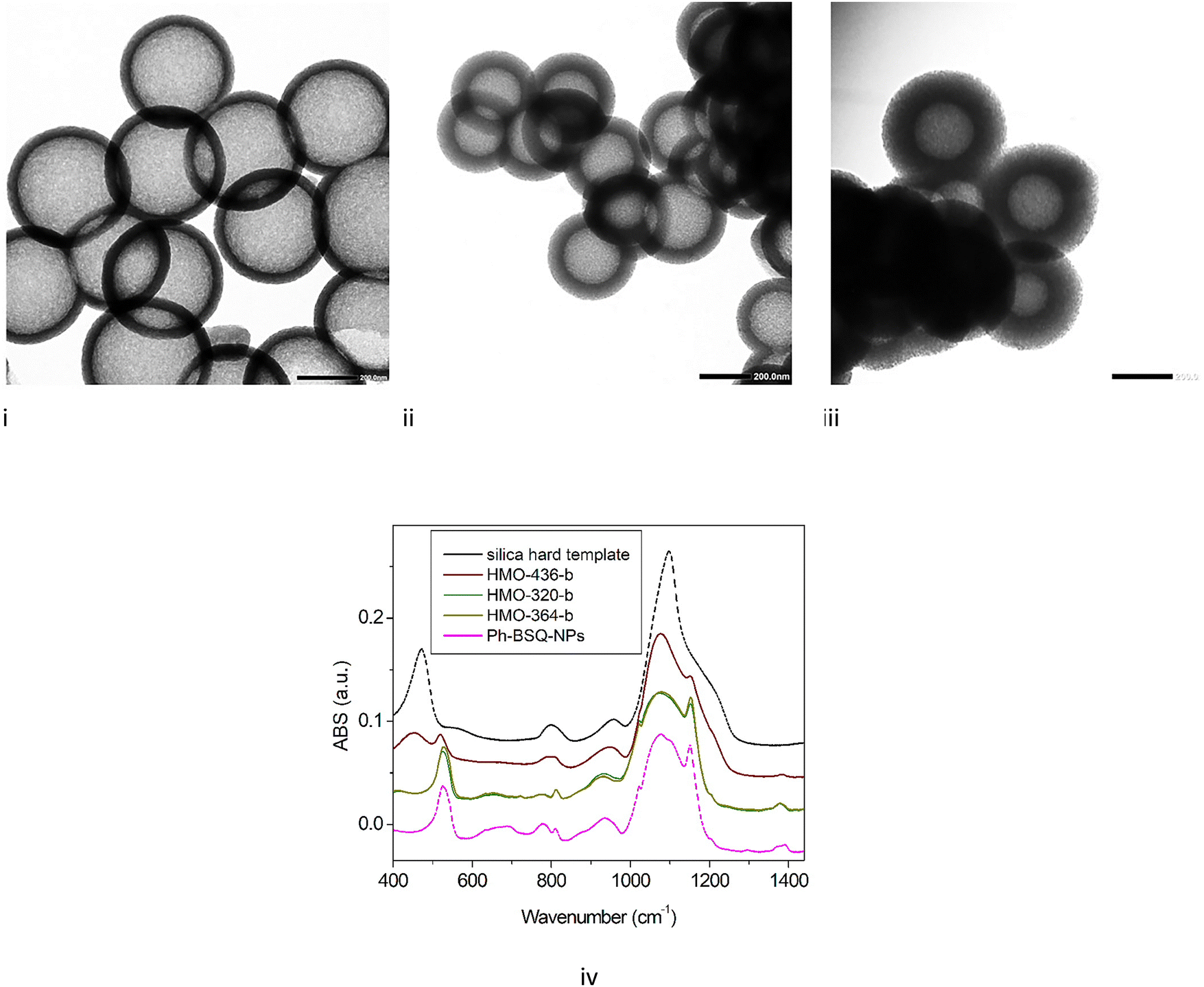 | ||
| Fig. 4 TEM images (scale 200 nm) of (i) HMO-436-b, with an average diameter of 436 ± 18 nm and a shell thickness of 55 ± 5 nm, (ii) HMO-320-c, with an average diameter of 320 ± 13 nm and a shell thickness of 50 ± 10 nm, and (iii) HMO-364-c, with an average diameter of 364 ± 22 nm and a shell thickness of 87 ± 6 nm. (iv) Comparison of MIR spectra for HMO-365-b, HMO-320-b, and HMO-364-b and the reference spectra (silica hard template and Ph-BSQ-NPs). | ||
Interestingly, for smaller sizes (364 and 320 nm), the IR spectra (Fig. 6) after step 3 (core alkaline etching) do not exhibit any Si–O–Si rocking feature; the main broad band appears as broad as the sample Ph-BSQ-NPs. It is therefore possible to confirm that step 2 has been completed using IR spectroscopy. This result agrees with the 29Si solid state NMR investigation (see Section SI-7, Fig. S10, ESI†). A similar result is also found for other intermediate diameters/thicknesses, so called HMO-350 (350 nm/67 mn) and HMO-250 (250 nm/54 nm) presented in SI-10, Fig. S13 (ESI†). Therefore, for HMOs with diameters between 250 and 364 nm, there is no significant redeposition of silica. SAXS applied to the latter (Fig. S14 in SI-10, ESI†) demonstrates that the porous network with a characteristic average parameter of 4 nm is transposed to smaller-sized HMOs. However, for smaller HMOs, this network becomes more disordered (broader q0 feature).
Sample HMO-436b, with a larger diameter, exhibits characteristic features of silica. It appears then that the etching protocol depends on the size of the internal template. One can suppose that silica hard templates start etching in ethanol, water, ammonia and CTAB before the addition of BTEB. This etching, which is less efficient without CTAB,21 could, however, depolymerize the hard template. The pre-etched smaller hard template is then etched more easily.
For HMOs with larger templates, etching must be optimized to reach a lower level of residual silica. To improve the etching process, three parameters are adjusted: time, number of etchings, and concentration of the solution. We found that increasing the etching time from 1 h to 4 h and doubling the Na2C03 concentration insignificantly affect silica etching (Fig. S17 in SI-12, ESI†). However, increasing the number of etching steps has much more impact (Fig. 5), and the amount of silica is strongly reduced after 2 etching cycles, as shown by the reduction of Qn species in NMR and the IR signatures at 440 and 1060 cm−1. The TEM also reveals that the organo-silica shell thickness is also reduced to 20 ± 5 nm, leading to more flexible HMOs. Etching 4 times for 4 h is significantly destructive for the HMO, and both Qn and Tn species disappear, as well as IR silica and organo-silica signatures. No HMO can be detected by TEM.
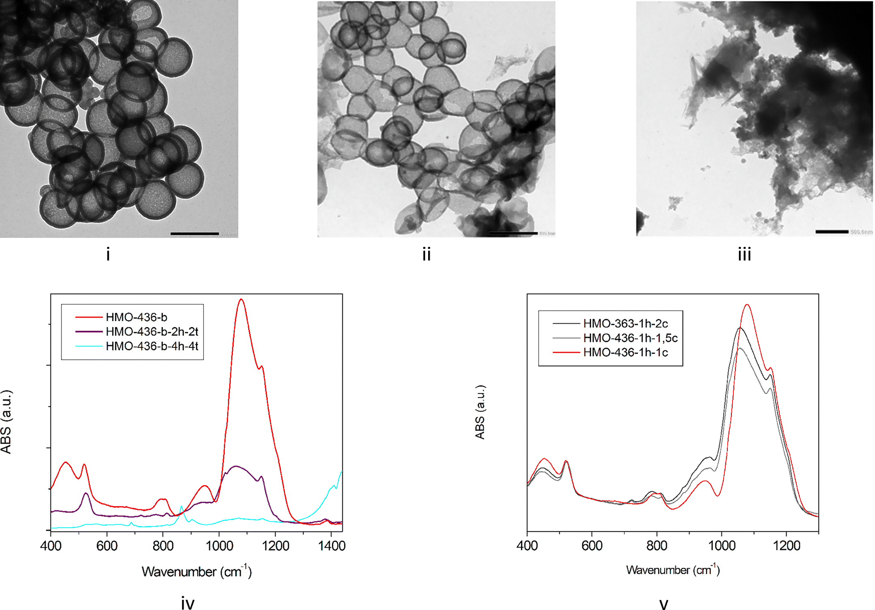 | ||
| Fig. 5 TEM (scale 500 nm), for HMO-436-b etched with Na2CO3 during 1 h (i), for HMO-436-b-2h-2t etched with Na2CO3 during 2 h twice (ii), for HMO-436-b-4h-4t etched with Na2CO3 during 4 h 4 times (iii). IR spectra of or HMO-436-b, HMO-436-b-2h-2t, HMO-436-b-4h-4t (iv). IR spectra for HMO-436-b-1h-1,5c, HMO-436-b-1h-2c samples etched with Na2CO3 with usual concentration, with concentration respectively multiplied by 1.5 and 2, respectively (v). | ||
It therefore appears that the best compromise for an optimized etching of these large HMOs is obtained by 2 etching cycles to avoid the saturation of the solution, adjusting the duration of the second step. Interestingly, a long second step can also be applied to form a flexible HMO required for some applications.14
C-HMO nanocargos
HMO-480-c and HMO-320-c are filled with Rhodamine (Rho) and Zn-phthalocyanine (Zn-Pc) dyes, respectively, and then incubated with cancer cells to prospect their use in biological and health applications.First, Rho dye is dissolved in ultra-pure water at a concentration of 5 mg mL−1 and mixed with a 0.5 mg mL−1 solution of HMO-480-c. The solution is successively centrifugated, sonicated and washed 5 times with milliQ water to remove excess Rho. The centrifugated final solution culot is mixed with 1300 μL of milliQ water, observed by fluorescence and incubated with cancer cells, showing the successful uptake of the nanoparticles within cells (Fig. 6i).
 | ||
| Fig. 6 (i) HMO-480-c fluorescence after insertion of Rho injected in a culture of LC50 cells gives rise to red spots within the cells compared with the control cells without any HMO. The brightest spots show the aggregation of HMO-480-c on dead cells. (ii) Cytotoxicity study of HMO-480-c nanoparticles. MCF-7 cells were incubated for 3 days with increasing doses of Rho-HMO-480-c, and then, cell survival was quantified by an MTT assay. The results are taken from an average of three points ± standard deviation. | ||
The cells in culture in 96-well plates are incubated with increasing doses of HMO-480-c nanoparticles for 3 days. At the end of the incubation, 0.5 mg mL−1 of MTT (synthetic substrate of a mitochondrial enzyme) is added to quantify the living cells. The MTT is incubated for 4 h at 37 °C in the cells and then aspirated, and 150 μL of a mixture of EtOH/DMSO (1![[thin space (1/6-em)]](https://www.rsc.org/images/entities/char_2009.gif) :1) was added. After stirring for 30 min, a homogeneous purple solution is obtained in the wells, which could be read with a plate reader. The results are reported in the cell viability curve shown in Fig. 6ii. We can conclude that the toxicity of HMO-480-c is very low under the conditions tested here, with an LC50 (half the lethal dose) at a concentration greater than 200 μg mL−1.
:1) was added. After stirring for 30 min, a homogeneous purple solution is obtained in the wells, which could be read with a plate reader. The results are reported in the cell viability curve shown in Fig. 6ii. We can conclude that the toxicity of HMO-480-c is very low under the conditions tested here, with an LC50 (half the lethal dose) at a concentration greater than 200 μg mL−1.
Second, 200 μL solutions of Zn-Pc dissolved in DMSO (concentration C1 equal to 0.1 mg mL−1, concentration C2 equal to 0.2 mg mL−1) are mixed with 400 μL of 0.5 mg mL−1 HMO-320-c solutions. The samples are dried and measured with IR spectroscopy, and the characteristic peaks of ZnPc are superimposed with the HMO-320-c spectrum (Fig. S19 in SI-13, ESI†). Based on IR transmission spectra, a simple calculation based on the extinction coefficient of the feature at 800 cm−1 indicates that the amount of ZnPc carried by the HMO is equal to 8 wt% of the total weight.
Fifteen μL of solution is added to 1 mL culture medium of two types of cancer cells: MDA-MB-231 (breast cancer cells) and LNCaP (prostate cancer cells) (Fig. 7). After incubation, the nanoparticles tend to aggregate within the cell culture. After 24 h, the fluorescence of Zn-Pc is measured, showing that filled HMOs are up-taken by cells.
 | ||
| Fig. 7 Optical microscopy (scale 150 μm) of two types of cancer cells incubated with HMO-365-c filled with ZnPc. The concentration is divided by 2 in MDA-MB-231 cells (i) and compared to that in LNCaP cells (ii). The first row of images represents cells without any HMO. | ||
Conclusion
In this study, we demonstrate that the same synthesis strategy can be applied to the reproducible fabrication of HMOs with external diameters ranging from 480 to 250 nm. An IR-assisted protocol is introduced to control, validate, and optimize each step of the fabrication process. For HMOs over 400 nm, the conditions for removing the hard silica template by chemical etching with Na2CO3 need to be fine-tuned according to the template size. Multiple etching cycles may reduce shell thickness and, in some cases, lead to the degradation of the hybrid structure. However, for HMOs with a diameter below 400 nm, we show that silica redeposition is not observed. Finally, two sizes of HMOs, loaded with two distinct dyes, were injected into and absorbed by pathological cells. Their low cytotoxicity holds great promise for future localized drug delivery applications.Conflicts of interest
There are no conflicts to declare.Acknowledgements
The authors thank Frank Godiard (Plateforme Microscopie Electronique et Analytique, Université de Montpellier) for TEM measurements, as well as Philippe Gaveau and Emmanuel Fernandez (Laboratoire de Mesures Physiques, Université de Montpellier, Ecole Nationale Supérieure de Chimie de Montpellier) for solid-state NMR experiments. Infrared measurements were carried out on the IRRAMAN technological platform of the University of Montpellier.References
- Hollow Mesoporous Silica Nanoparticles with Tunable Structures for Controlled Drug Delivery Y. Li, N. Li, W. Pan, Z. Yu, L. Yang and B. Tang, ACS Appl. Mater. Interfaces, 2017, 9(3), 2123–2129, DOI:10.1021/acsami.6b13876.
- Chemical Synthesis and Multihybridization of Small-Sized Hollow Mesoporous Organosilica Nanoparticles Toward Advanced Theranostics Y. Huang, C. Zhang, L. Zhang, X. Chen and W. Fan, Acc. Chem. Res., 2024, 57(24), 3465–3477, DOI:10.1021/acs.accounts.4c00502.
- Nanotechnology-Driven Delivery of Caffeine Using Ultradeformable Liposomes-Coated Hollow Mesoporous Silica Nanoparticles for Enhanced Follicular Delivery and Treatment of Androgenetic Alopecia N. Thepphankulngarm, S. Manmuan, N. Hirun and P. Kraisit, Int. J. Mol. Sci., 2024, 25(22), 12170, DOI:10.3390/ijms252212170.
- Multilayer pH-responsive hollow mesoporous silica nanoparticles with charge reversal for drug delivery and real-time monitoring by fluorescence S. Wu, Y. Teng, Z. Qu, L. Bai, W. Yang, Q. Wu and G. Zhang, Colloids Surf., A, 2024, 690, 133831, DOI:10.1016/j.colsurfa.2024.133831.
- Development of mesoporous silica-based nanoprobes for optical bioimaging applications, B. Sun, X. Zhen and X. Jiang, Biomater. Sci., 2021, 9, 3603–3620, 10.1039/D1BM00204J.
- Hollow mesoporous silica nanoparticles for intracellular delivery of fluorescent dye H. Guo, H. Qian, S. Sun, D. Sun, H. Yin, X. Cai, Z. Liu, J. Wu, T. Jiang and X. Liu, Chem. Central J., 2011, 5, 1, DOI:10.1186/1752-153X-5-1.
- Synthesis of MnSiO3 decorated hollow mesoporous silica spheres and its promising application in environmental remediation, Q. Gao, H. T. Li, Y. Ling, B. Han, K. S. Xia and C. G. Zhou, Microporous Mesoporous Mater., 2017, 241, 409–417, DOI:10.1016/j.micromeso.2016.12.026.
- Tunable hollow mesoporous organosilica for efficient adsorption of heavy metal ions from water M. Cheng, Y. Liu, H. Jiang, C. Li, S. Sunab and S. Hu, Inorg. Chem. Front., 2024, 11, 4695–4710, 10.1039/D4QI00772G.
- Mesoporous Organosilica Hollow Nanoparticles: Synthesis and Applications, Z. Teng, W. Li, Y. Tang, A. Elzatahry, G. Lu and D. Zhao, Adv. Mater., 2019, 31, 1707612, DOI:10.1002/adma.201707612.
- A soft–hard template approach towards hollow mesoporous silica nanoparticles with rough surfaces for controlled drug delivery and protein adsorption, H. Zhang, H. Xu, M. Wu, Y. Zhong, D. Wanga and Z. Jiao, J. Mater. Chem. B, 2015, 3, 6480–6489, 10.1039/C5TB00634A.
- Synthesis of Monodispersed Hollow Mesoporous Organosilica and Silica Nanoparticles with Controllable Shell Thickness Using Soft and Hard Templates, Y. Fujii, S. Zhou, M. Shimada and M. Kubo, Langmuir, 2023, 39, 4571–4582, DOI:10.1021/acs.langmuir.2c03121.
- One-step synthesis of hollow periodic mesoporous organosilica spheres with radially oriented mesochannels, N. Ma, Y. Deng, W. Liu, S. Li, J. Xu, Y. Qu, K. Gan, X. Sun and J. Yang, Chem. Commun., 2016, 52, 3544–3547, 10.1039/C5CC10106A.
- Surfactant-free synthesis of hollow mesoporous organosilica nanoparticles with controllable particle sizes and diversified organic moieties, N. Koike, W. Chaikittisilp, A. Shimojima and T. Okubo, RSC Adv., 2016, 6, 90435, 10.1039/C6RA22926C.
- Synthesis of Porous Hollow Organosilica Particles with Tunable Shell Thickness, M. A. Al-Khafaji, A. Gaál, B. Jezsó, J. Mihály, D. Bartczak, H. Goenaga-Infante and Z. Varga, Nanomaterials, 2022, 121172, DOI:10.3390/nano12071172.
- Swellable hollow periodic mesoporous organosilica capsules with ultrahigh loading capacity for hydrophobic drugs, S. Teng, Y. Han, Y. Hub, J. Li, M. Wang, Z. Guo and W. Yang, J. Colloid Interface Sci., 2023, 630, 266–273, DOI:10.1016/j.jcis.2022.10.017.
- Size-tuning of hollow periodic mesoporous organosilica nanoparticles (HPMO-NPs) using a dual templating strategy, I. El Moujarrad, R. Le Parc, C. Carcel, G. Toquer, P. Trens, D. Maurin, C. Gauthier, M. Gary-Bobo, P. Dieudonné, L. D. Carlos, M. Wong Chi Man and J.-L. Bantignies, J. Sol-Gel Sci. Technol., 2023, 107, 302, DOI:10.1007/s10971-023-06139-1.
- Synthesis of Stober silica nanoparticles in solvent environments with different Hansen solubility parameters, P. Sivolapov, O. Myronyuk and D. Baklanstober, Inorg. Chem. Commun., 2022, 143, 109769, DOI:10.1016/j.inoche.2022.109769.
- Revising the synthesis of Stöber silica nanoparticles: A multivariate assessment study on the effects of reaction parameters on the particle size R. S. Fernandes, I. M. Raimundo Jr and M. Fernanda Pimentel, Colloids Surf., A, 2019, 577, 1–7 CrossRef CAS.
- Colloidal HPMO nanoparticles: silicaetching chemistry tailoring, topological transformation, and nanobiomedical applications. Y. Chen, P. Xu, H. Chen, Y. Li, W. Bu, Z. Shu, Y. Li, J. Zhang, L. Zhang, L. Pan, X. Cui, Z. Hua, J. Wang, L. Zhang and J. Shi, Adv. Mater., 2013, 25(22), 3100–3105, DOI:10.1002/adma.201204685.
- Influence of the hydrolysis and condensation time on the preparation of hybrid materials. E. C. Nassor, L. R. Ávila, P. F. D. S. Pereira, K. J. Ciuffi, P. S. Calefi and E. J. Nassar, Mater. Res., 2011, 14(1), 1–6, DOI:10.1590/S151614392011005000003.
- A cationic surfactant assisted selective etching strategy to hollow mesoporous silica spheres. X. Fang, C. Chen, Z. Liu, P. Liu and N. Zheng, Nanoscale, 2011, 3, 1632, 10.1039/C0NR00893A.
Footnote |
| † Electronic supplementary information (ESI) available. See DOI: https://doi.org/10.1039/d5nj00432b |
| This journal is © The Royal Society of Chemistry and the Centre National de la Recherche Scientifique 2025 |