
 Open Access Article
 This Open Access Article is licensed under a Creative Commons Attribution-Non Commercial 3.0 Unported Licence
Emerging fiber-based neural interfaces with conductive composites
Chihyeong
Won†
ab,
Sungjoon
Cho†
a,
Kyung-In
Jang
cd,
Jang-Ung
Park
 e,
Jeong Ho
Cho
f and
Taeyoon
Lee
*a
e,
Jeong Ho
Cho
f and
Taeyoon
Lee
*a
aSchool of Electrical and Electronic Engineering, Yonsei University, 50 Yonsei-ro, Seodaemun-gu, Seoul, 03722, Republic of Korea. E-mail: taeyoon.lee@yonsei.ac.kr
bAndrew and Peggy Cherng Department of Medical Engineering, Division of Engineering and Applied Science, California Institute of Technology, Pasadena, CA 91125, USA
cDepartment of Robotics and Mechatronics Engineering, Daegu Gyeonbuk Institute of Science and Technology, Daegu, 42988, Republic of Korea
dENSIDE Corporation, Daegu, 42988, Republic of Korea
eDepartment of Materials Science and Engineering, Yonsei University, 50 Yonsei-ro, Seodaemun-gu, Seoul, 03722, Republic of Korea
fDepartment of Chemical and Biomolecular Engineering, Yonsei University, 50 Yonsei-ro, Seodaemun-gu, Seoul, 03722, Republic of Korea
First published on 1st April 2025
Abstract
Neural interfaces that enable bidirectional communication between neural systems and external devices are crucial for treating neurological disorders and advancing brain–machine interfaces. Key requirements for these neural interfaces are the ability to modulate electrophysiological activity without causing tissue damage in the nerve system and long-term usability. Recent advances in biomedical neural electrodes aim to reduce mechanical mismatch between devices and surrounding tissues/organs while maintaining their electrical conductivity. Among these, fiber electrodes stand out as essential candidates for future neural interfaces owing to their remarkable flexibility, controllable scalability, and facile integration with systems. Herein, we introduce fiber-based devices with conductive composites, along with their fabrication technologies, and integration strategies for future neural interfaces. Compared to conventional neural electrodes, fiber electrodes readily combine with conductive materials such as metal nanoparticles, carbon-based nanomaterials, and conductive polymers. Their fabrication technologies enable high electrical performance without sacrificing mechanical properties. In addition, the neural modulation techniques of fiber electrodes; electrical, optical, and chemical, and their applications in central and peripheral nervous systems are carefully discussed. Finally, current limitations and potential advancements in fiber-based neural interfaces are highlighted for future innovations.
Wider impactWith the growing focus on neural interfaces, fiber-based neural interfaces have emerged as a versatile and transformative platform for addressing critical challenges in neural modulation. Their structural properties, such as flexibility and a miniaturized insertion area, enable a seamless interaction with the central and peripheral nervous systems. By incorporating conductive composites and multifunctional capabilities, fiber-based neural interfaces hold promise as alternative tools for treating neurological disorders. This review presents an overview of conductive nanocomposites, fabrication processes, neural modulation method integration strategies, and in vivo applications of neural modulation. To address current limitations in neural interfacing, advancements in fiber-based devices emphasizing long-term stability and enhanced multifunctional capabilities are highlighted. This review aims to inspire innovation and accelerate the clinical translation of fiber-based neural interfaces for future biomedical applications. |
1. Introduction
Implantable neural interfaces, widely studied for their role in decoding the intricate organization of neural networks, have advanced engineering approaches to treating neurological disorders.1–3 Devices for neural recording and modulation, combined with electrical,4 optical,5 or chemical6 stimulation functions, enable the diagnosis and control of chronic neurological and psychological conditions such as Parkinson's disease (PD),7 epilepsy,8,9 depression,10 and cognitive impairment.11 Recently, neural interfaces have been utilized increasingly in the treatment of various chronic diseases, targeting both the central and peripheral nervous systems.12–14 For example, devices such as brain–machine interfaces implanted in the cortex can record neural activities and modulate electrical impulses in deep regions of the brain to treat symptoms of disorders.15,16 Similarly, electrode arrays implanted epidurally and percutaneously in the spinal cord are used for chronic pain management and to promote motor function recovery after spinal cord injury.17,18 In the peripheral nervous system, neural interfaces primarily manipulate sensory and motor functions. Furthermore, as the understanding of the central–peripheral nervous system interaction expands, peripheral nerve modulation is being investigated for treating a wide range of conditions beyond conventional approaches.19 These advancements emphasize the need for innovative devices capable of seamlessly interfacing with and regulating complex neural networks for precise modulation in both central and peripheral nervous systems.Fiber-based electronics have emerged as promising candidates for biomedical devices, such as deep brain stimulation (DBS) electrodes, medical sutures, vascular scaffolds, and minimally invasive needles.20–24 Their fiber structure enables minimally invasive designs, conformal contact with a nerve bundle, and flexibility to minimize mechanical mismatch. As neural interfaces, miniaturized and flexible fiber devices can be implanted for a long time in both the central and peripheral nervous systems with reduced foreign body responses (FBRs).25,26 These neural interfaces are mainly used for (1) recording single-neuron spikes and local field potentials (LFPs)27,28 and (2) modulating neuronal activity using various stimulation methods.29,30 Fiber electrodes are composed of different conductive and polymeric materials, which serve as the substrates. The advancements in materials and fabrication processes enhance the performance of fiber electrodes by employing neural signal recording.31 Moreover, these fiber electrodes can be integrated seamlessly with neural modulation techniques, such as electrical and chemical methods.32 Therefore, fiber-based neural interfaces hold significant potential for long-term neural recording and modulation applications in both the central and peripheral nervous systems, driving the development of next-generation biomedical devices.
Herein, we overview recent advancements in fiber-based neural interfaces, focusing on advanced materials, fabrication processes, and integration strategies for clinical applications in neurological disorders (Fig. 1). We first highlight various conductive composites used to develop fiber electrodes. The conductive networks composed of these composites within the fibers are fundamental to serve as the core for precisely recording neural activities evoked from various modulations. We then discuss the fabrication process for developing fiber structures, ranging from a single fiber electrode to a complicated design. Based on conductive composites and fiber fabrication processes, integration strategies for different neural modulation methods, such as electrical, optical, chemical, and other functional techniques applicable to neural interfaces, are discussed. Finally, demonstrated applications in neural recording and modulation within both the central and peripheral nervous systems are introduced, discussing the practical application potential of fiber-based neural interfaces for treating neurological disorders. We also discuss promising opportunities and remaining challenges in the emerging field of fiber-based interfaces.
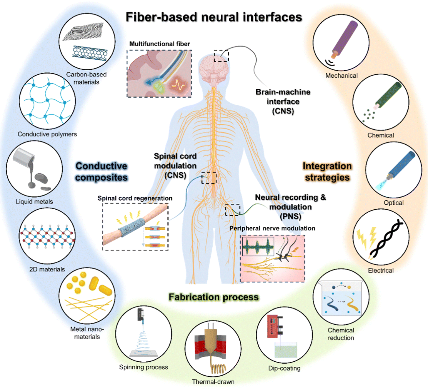 | ||
| Fig. 1 Introduction of emerging fiber-based neural interfaces. | ||
2. Conductive composites for fiber electrodes
In general, selecting materials for the fabrication of fiber electrodes involves combining electrically conductive elements with elastic fibrous matrices.33–36 This section discusses the material requirements for minimizing foreign body responses (FBRs) in fiber-based neural interfaces for achieving the optimal electrical–mechanical properties in fiber electrodes.2.1. Material conditions for minimizing foreign body responses in fiber electrodes
Minimizing the FBR is crucial for fiber electrodes specifically designed for neural interfaces, as the FBR can lead to device encapsulation, increased impedance, reduced recorded signal fidelity, eventually degrading device functionality over time.30,37–42 The FBR refers to the immune response of tissues to implanted materials, often characterized by sustained glial activation, demyelination, the blood–brain barrier, inflammantation, fibrous encapsulation, and tissue remodeling around the implanted device.43–45 One of the main causes of the FBR is the mechanical mismatch between the rigid fiber electrodes and the surrounding soft brain tissue (elastic modulus = ≈10–150 kPa), alongside other contributing factors such as the physical properties of the implanted materials, surface chemistry, and implant design.46,47 The mechanical mismatch between the fiber electrodes and the surrounding brain tissue generates sustained stress at the tissue device interface, exacerbating the FBR and leading to degrading device functionality of fiber-based neural interfaces over time.30,37,40–42 The formation of a fibrous capsule, encapsulated around the fiber-based interfaces by the FBR, leads to an obstruction in electrical connections between the neurons and implanted electrodes and a reduction in the quality of measured neural signals.30,48 Additionally, the FBR from the mechanical mismatch prevents reliable long-term monitoring beyond several months, limiting the effectiveness of fiber-based neural interfaces for chronic neurological conditions.To address mechanical mismatch issues, materials of fiber electrodes with mechanical stiffness similar to that of brain tissue have been studied to minimize the FBR.30,37,39 By matching the elastic modulus of the electrode materials with that of the soft brain tissue, stress at the tissue–device interface can be minimized, thereby reducing the likelihood of immune activation and subsequent inflammatory responses, while elevating recorded signal consistency and long-term device performance.30,37,39,40 However, materials with an elastic modulus similar to that of brain tissue, such as polydimethylsiloxane (PDMS), poly(styrene–butadiene–styrene) (SBS), and Ecoflex, are inherently non-conductive and thus unsuitable for fiber electrode applications.48–50 To render these materials appropriate for neural interfaces, they must be combined with conductive elements or effectively blended with conductive composites, such as carbon-based materials and metal nanoparticles, enabling the desired mechanical properties and electrical functionality required for fiber-based neural electrodes.24,51–55 Additionally, stretchable materials such as liquid metals or conductive polymers can be directly fabricated into fiber forms, achieving high conductivity and low elastic modulus.56–59 Stretchable and soft materials such as liquid metals or conductive polymers provide an alternative approach, as they naturally combine the required electrical properties with mechanical flexibility, closely matching the softness of brain tissue.56,57 In this work, we classified conductive composites into five categories: carbon-based materials, conductive polymers, liquid metals (LMs), 2D materials, and metal nanomaterials. The primary performance parameters for these conductive composites were evaluated based on electrical conductivity, elastic modulus, and impedance, as shown in Table 1.
| Conductive composites | Conductive fiber materials | Electrical conductivity (S cm−1) | Elastic modulus (kPa) | Impedance (Ohms@1 kHz) | Ref. |
|---|---|---|---|---|---|
| Carbon-based materials | Graphene | 1.0 × 10³–2 × 10⁵ | 7.7 × 10⁶–1.35 × 10⁸ | — | 60,61 |
| Graphene oxide liquid crystals (GOLC) | 20–2.5 × 10² | 1.4 × 10⁵–4.9 × 10⁶ | — | 62,63 | |
| Ag-doped graphene | 81–2.8 × 10² | 3.34 × 10⁵ | — | 64 | |
| Carbon nanotube (CNT) | 2.8 × 10³–5.84 × 10⁴ | 1.12 × 10⁵–7.2 × 10⁷ | 250 | 65–67 | |
| CNT/Cu | 2.3 × 10⁵–4.7 × 10⁵ | — | — | 68 | |
| Conductive polymers | Poly(2,3-dihydrothieno-1,4-dioxin)-poly(styrenesulfonate) (PEDOT:PSS) | 2–231 | 1.45 × 10³–9.0 × 10⁵ | 800–2.0 × 10⁴ | 56,59,69 |
| Polyaniline (PANI) | 3.72 × 10⁻⁴–1.68 | — | — | 70,71 | |
| Hydrogel (polymethyl acrylate (PMA)/sodium polyacrylate (PAAS)) | 3.5 × 10⁻³ | 5.6 × 10³ | — | 72 | |
| Hydrogel (peptide nucleic acids (PNA)/PMA) | 6.9 × 10⁻³ | 2.27 × 10³ | 73 | ||
| Liquid metals | Eutectic gallium–indium (EGaIn) | 435–2.6 × 10³ | 2.16 × 10³–3.2 × 10³ | — | 74,75 |
| Ag/EGaIn/FAS-17 (heptadecafluoro-1,1,2,2-tetradecyltrimethoxysilane) | 2.145 × 10³ | 670 | — | 76 | |
| Galinstan (Ga, In, Sn) | 3.4 × 10⁴ | 2 × 10³ | 3860 | 57,77 | |
| 2D materials | MXene | 5.15 × 10²–1.2 × 10⁴ | 2.75 × 10⁶–1.22 × 10⁸ | — | 78–80 |
| MoS2 | 1.23 | 5.0 × 10⁴ | — | 81,82 | |
| Metal nanomaterials | Ag nanoparticle (AgNPs)/PU | 2.0 × 10⁴–1.4 × 10⁶ | 65.9 | — | 83,84 |
| AgNPs/Ag nanoflowers (AgNFs)/polyvinyl alcohol (PVA) | 2.09 × 10⁴–3.21 × 10⁵ | 5.5 × 10⁴ | — | 85 | |
| AuNPs/polyurethane (PU) | 768 | 170 | 2880 | 37 |
2.2. Conductive materials suitable for the electrical properties of fiber electrodes
A range of carbon-based nanomaterials with both 1D and 2D architectures have been frequently applied in the development of flexible electronics, owing to their high electrical conductivity (∼2 × 10⁵ S cm−1) and robust mechanical properties.61–68,86 Especially, graphene and carbon nanotubes (CNTs) are predominantly employed for the construction of fiber electrodes owing to their advantageous electrical conductivity and mechanical elasticity that enable the development of highly stable and high performance electrochemical devices.60–68 Graphene, characterized as a single-atom-thick 2D sheet of sp2-bonded carbon, stands out for its remarkable electrical and mechanical properties. Graphene oxide (GO), an oxidized form of graphene, contains oxygen functional groups that improve dispersibility in solution-based processes, making it a versatile precursor for various applications. Through chemical or thermal reduction, GO can be converted into reduced graphene oxide (rGO), which restores electrical conductivity by partially removing these oxygen-containing groups.61,64,65 Xin et al. used small-sized graphene oxide (SMGO) sheets and large-sized graphene oxide (LGGO) sheets to create an intercalated and compact fiber structure.60 The LGGO sheets established a well-aligned backbone, while the SMGO sheets filled the voids between them to enhance the compactness of sheets without disrupting the alignment of sheets, allowing for an optimal structure that balances both attributes by adjusting the SMGO amounts (Fig. 2a). Following high-temperature annealing, the initially insulating GO fibers were converted into ordered graphene fibers with high thermal and electrical conductivity (2.21 × 10³ S cm−1). In addition, Zhou et al. fabricated CNT-based fiber electrodes by embedding single-walled carbon nanotubes (SWCNTs) within a thermoplastic elastomer (TPE) sheath, resulting in a coaxial structure tailored for strain sensing applications (Fig. 2b).65 The TPE layer served as an insulating outer shell, preventing short-circuiting and shielding the fibers from environmental damage, while the SWCNT core offered excellent conductivity and improved mechanical resilience and strain sensitivity. After an acetone bath treatment to eliminate acid residues, the fibers adopted a belt-like configuration, exhibiting a notable conductivity (2.80 × 10³ S cm−1).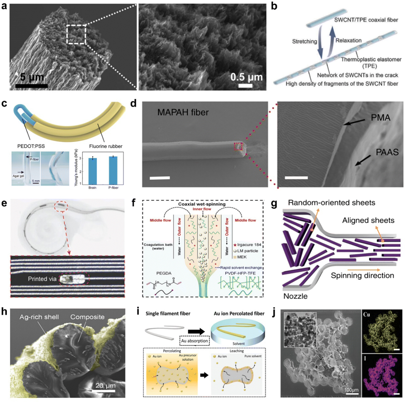 | ||
| Fig. 2 Materials for fiber-based neural interfaces. (a) SEM images showing the morphology of the graphene fibers. Reproduced with permission.60 Copyright 2015, The American Association for the Advancement of Science. (b) Schematic presenting the coaxial SWCNT-based stretchable conductive fiber.65 Reproduced with permission. Copyright 2018, John Wiley & Sons. (c) Schematic illustration of the PF-OECT. Reproduced with permission.56 Copyright 2023, John Wiley & Sons. (d) SEM images of a MAPAH fiber. Reproduced with permission.72 Copyright 2018, Springer Nature. (e) LM high density interconnect inserted into a 3D printed cochlea model. Reproduced with permission.57 Copyright 2023, John Wiley & Sons. (f) Schematic of the setup used for producing LM sheath-core microfibers. Reproduced with permission.74 Copyright 2021, The American Association for the Advancement of Science. (g) Schematic illustration of the reconstruction of MXene layers into fibers. Reproduced with permission.78 Copyright 2020, Springer Nature. (h) SEM images of AgNP embedded fibers. Reproduced with permission.83 Copyright 2018, John Wiley & Sons. (i) Schematic illustration of Au reduction and leaching process. Reproduced with permission.37 Copyright 2022, John Wiley & Sons. (j) SEM images of cross sectional CuINP embedded fibers. Reproduced with permission.87 Copyright 2024, John Wiley & Sons. | ||
In addition to carbon-based materials, conductive polymers such as poly(2,3-dihydrothieno-1,4-dioxin)-poly(styrenesulfonate) (PEDOT:PSS) and polyaniline (PANI), and conductive hydrogels such as polymethyl acrylate (PMA) and sodium polyacrylate (PAAS) are also widely employed owing to their inherent conductivity.56,59,70,72,73 Conductive polymers, typically available in the solution form, facilitate solution-based processing, allowing for fabrication through methods such as spinning, thermal drawing, and dip coating methods, rendering conductive polymers highly advantageous for forming efficient conductive structures across various applications of fiber electronics.88–90 Feng et al. introduced a fully polymer-based fiber organic electrochemical transistor (PF-OECT) aimed at prolonged in vivo chemical sensing within the brain (Fig. 2c).56 Utilizing PEDOT fibers as the conductive elements, along with fluorine rubber insulation, the PF-OECT maintained the electrical properties necessary for effective signal transduction. Enhanced by high-temperature annealing, the device exhibited stable and sensitive electrochemical performance, making it capable of reliably detecting molecules such as ascorbic acid over time. In addition, Zhao et al. developed highly stretchable and conductive hydrogel fibers inspired by the structural organization of spider silk (Fig. 2d).72 Using a straightforward spinning technique, sodium polyacrylate (PAAS) hydrogel fibers with orderly polymer chain alignment were produced, then coated with a polymethyl acrylate (PMA) layer to create water-resistant core–shell PMA–PAAS hydrogel (MAPAH) fibers. The crystalline and amorphous domains within the fibers are advantagous: as liquids, LMs are inherently soft and adaptable to reversible structural alignment, endowing the fibers with notable tensile strength, elasticity, and conductivity (2 × 10⁻² S cm−1). Although conductive polymers offer flexibility and processing advantages, they have significantly lower conductivity compared to metals.24,30 In contrast, LMs exhibit conductivity comparable to traditional metals, with unique deformable applications, combining high electrical performance with exceptional material compliance.57,74–76,91 Wang et al. engineered stretchable, high-density interconnects using LM-based technology, integrating LM particles into silicone through a laser-engraved micropatterning approach (Fig. 2e).57 The LM interconnects provided high conductivity similar to that of solid metals while maintaining flexibility due to the inherent fluidity of liquid metals, and the silicone matrix offers mechanical stability. Besides, Zheng et al. developed elastic and highly conductive microfibers with the LM core encased in a fluoroelastomer sheath, using a coaxial wet-spinning process (Fig. 2f).74 The LM sheath-core microfibers enhanced both conductivity (4.35 × 10² S cm−1) and mechanical resilience (700% of maximum strain), with the sheath providing stability and the LM core ensuring excellent electrical performance. After an activation process involving freezing and stretching, the microfibers exhibited stable conductivity, showing minimal resistance changes even under 200% strain.
In addition to LM, 2D materials, such as Mxene and transition metal dichalcogenides (TMDCs), are also utilized due to their intrinsically high electrical conductivity.78–82 Eom et al. developed highly conductive, pure MXene fibers via a continuous wet-spinning technique without the need for additives or binders (Fig. 2g).78 The Ti3C2Tx MXene nanosheets were prepared in a highly concentrated aqueous dispersion and formed into flexible, meter-scale fibers with a high electrical conductivity of 7.71 × 10³ S cm−1. The MXene fibers demonstrated both flexibility with strong electrical performance, making them suitable for electrical devices.
Alongside the previously discussed conductive materials, metal nanomaterials, such as metal nanoparticles and metal nanowires, are also utilized in composite synthesis and have been applied as fiber-shaped electrodes.37,83–85,92–96 Lee et al. created stretchable microfiber strain sensors by embedding silver nanoparticles (AgNPs) into a multifilament fiber structure (Fig. 2h).83 Through a simple process involving the absorption and reduction of silver ions within the stretchable fiber matrix, the resulting sensors exhibited high sensitivity and an extended strain-sensing range. The multifilament design, along with Ag-rich shells, allowed the sensor to maintain high gauge factors and elasticity. In addition, Won et al. fabricated elastomeric fiber electrodes embedded with gold nanoparticles (AuNPs), which exhibited excellent biocompatibility, and were designed for chronic brain–machine interface applications (Fig. 2i).37 The AuNP embedded conductive fiber exhibited a high conductivity (7.68 × 10⁴ S m−1) and a low impedance (2.88 × 10³ Ω at 1 kHz). Furthermore, Yoon et al. engineered a highly stretchable thermoelectric fiber sensor by embedding copper(I) iodide (CuI) nanoparticles into polyurethane (PU) fibers, achieving a multimodal sensing capability for temperature, strain, and pressure (Fig. 2j).87 Using a novel chemical synthesis method, dense CuI networks were uniformly embedded within the PU matrix, achieving a high electrical conductivity (2.97 S cm−1).
2.3. Non-conductive materials suitable for the mechanical properties of fiber electrodes
For fiber electrodes to be effectively utilized in neural interfaces, their conductivity must be optimized while ensuring biocompatibility and mechanical properties that minimize FBRs.37–40,42 Suitable mechanical properties are essential to ensure both functional integration with neural tissue and long-term in vivo stability.30,41 However, because most conductive composites used as fiber electrodes are typically rigid, conductive fiber materials are often either made from intrinsically soft materials or embedded within soft matrices to provide the necessary flexibility and compliance.37,40,42 In particular, conductive polymers and LMs are commonly employed as representative intrinsically soft materials.54,55 Feng et al. introduced a fully polymer-based fiber organic electrochemical transistor (PF-OECT) for prolonged in vivo chemical sensing within the brain (Fig. 2c).56 Constructed solely from conductive polymers, including PEDOT fibers for electrodes and channels, and insulated with the fluorine rubber, the PE-OECT demonstrated mechanical compatibility with brain tissue, matching its Young's modulus (3.15 kPa). Consequently, the PF-OECT demonstrated consistent conductivity and monitoring capabilities for up to 14 days, when implanted in the brain of a mouse, underscoring its suitability for chronic neural sensing applications. While conductive polymers provided biocompatibility and a low elastic modulus, limited conductivity and high impedance of conventional conductive polymers positioned LMs as promising alternatives for research.57,97,98 LMs are regarded as promising materials for conductive fiber electronics due to high electrical conductivity, stretchability, self-healing capability, and biocompatibility. Moreover, LMs possess an exceptionally low gauge factor, maintaining high conductivity even under mechanical deformation caused by the dynamic body movements.57,97,98 However, challenges remain, particularly in LM embrittlement and electrohydrodynamic instability in electronic devices.99–102 Additionally, while liquid metals exhibit minimal toxicity in small amounts, further research is needed to validate their long-term biocompatibility and to develop advanced encapsulation techniques for enhanced safety in healthcare applications.In addition to the intrinsically soft materials, embedding metal nanomaterials within soft matrices preserves the intrinsic conductivity of the metal nanomaterials while maintaining the low elastic modulus of the soft materials.37,83–85,92–95,103 By synthesizing metal nanomaterials within polymers with a brain-like elastic modulus, a low modulus suitable for neural applications can be achieved.37 Won et al. embedded AuNPs into low-modulus polyurethane (PU) with an elastic modulus of 100 kPa to create fiber-shaped electrodes, achieving a final composite modulus of 170 kPa (Fig. 2i). Notably, the use of commercial spandex fibers enhanced accessibility and provided an elastic modulus similar to that of neural tissue (10–150 kPa), thereby endowing the fiber-shaped electrodes with mechanical properties well-suited for application as neural interfaces.
3. Fabrication process of fiber devices
In the fabrication of conductive fiber-based neural interfaces, various factors must be carefully considered, including the stability, cost, mechanical properties of the fibers, and compatibility with intended integration strategies. Traditionally, templating and microfluidic methods have been employed as conventional approaches to fiber fabrication, offering precise control over fiber morphology and material composition.104–106 The templating method relies on predefined structures or sacrificial molds to shape fibers, allowing for highly controlled architectures with reproducible features. Similarly, microfluidic techniques utilize controlled fluid dynamics in microchannels to create continuous, structured fibers, often enabling multi-phase material integration. Recently, to satisfy the requirements for the fabrication of conductive fiber-based neural interfaces, four primary fabrication methods are commonly utilized: spinning, thermal drawing, dip coating, and chemical reduction methods. This section will discuss each of the fabrication techniques in detail.3.1. Spinning methods: electro/dry/wet
Spinning methods are fundamental techniques for fiber production, involving the coagulation of liquid-phase materials to create one-dimensional structures in the fiber form. Among typical spinning methods, electrospinning, dry spinning, and wet spinning are the most commonly used processes.107,108 Electrospinning, in particular, applies an electric field to a polymer solution or melt, creating a charged jet that stretches and solidifies as it moves toward a grounded collector.109–111 Electrospinning enables the production of fine, continuous fibers with a controlled morphology and porosity, offering high surface area, uniformity, and structural integrity.109,111,112 However, typical electrospinning techniques, while capable of producing nano- and microscale fibrous mats, have limitations in achieving the precise fiber alignment and structured patterning required for specialized applications.109,111,112 The lack of precise fiber alignment and structured patterning can result in randomly oriented fibers and non-uniform distribution, which reduces the reproducibility and functional integration of the fibers in targeted applications such as neural interfaces.113 To address the lack of precise fiber alignment and structured patterning, Li et al. optimized solution formulations and processing parameters to enable low-voltage electrospinning patterning for fabricating extracellular matrix-derived fibers (Fig. 3a). By carefully controlling the rheological properties of the electrospinning solution, finely tuned, patterned fibers were produced. In addition to fiber alignment and structured patterning challenges, typical electrospinning techniques also face challenges in seamlessly integrating electronic systems with biological tissues owing to mechanical mismatch. Orbital spinning methods, which involve rotating a solution around a target to creat bioelectronics fibers, allowing the fibers to be precisely tethered to biological surfaces, have been introduced to address integration challenges in seamlessly integrating electronic systems with biological tissues (Fig. 3b).114 Guided by the shape and position of the target, orbital spinning methods facilitate the formation of open, flexible networks that can adhere intimately to surfaces without the need for a substrate, making them suitable for seamless integration with biological tissues. | ||
| Fig. 3 Spinning methods including electrospinning, dry spinning, and wet spinning. (a) Schematic illustration of a low-voltage electrospinning patterning system for extracellular matrix-derived fibers. Reproduced with permission.113 Copyright 2019, American Chemical Society. (b) Organic bioelectronic fibers augment living systems with imperceptible designs. Reproduced with permission.114 Copyright 2024, Springer Nature. (c) Dry spinning process for continuous and highly tough graphene fibers. Reproduced with permission.115 Copyright 2017, Royal Society of Chemistry. (d) Schematic illustration and SEM images of AgNW/AgNPs embedded conductive fibers. Reproduced with permission.95 Copyright 2015, John Wiley & Sons. (e) Stretchable hydrogel fibers capable of self-healing and energy harvesting. Reproduced with permission.73 Copyright 2020, Elsevier. (f) Wet-spinning process for creating highly electroconductive MXene fibers on a large scale. Reproduced with permission.78 Copyright 2020, Springer Nature. (g) One-step wet-spinning approach for coaxial fibrous supercapacitors. Reproduced with permission.116 Copyright 2024, American Chemical Society. | ||
Dry spinning is a fiber fabrication technique where a polymer or material solution is extruded through a spinneret into a controlled airflow or heated chamber, allowing the solvent to evaporate and solidify the material into continuous fibers without requiring a coagulation bath.115,117 Tian et al. developed a continuous graphene fiber with high toughness using a dry spinning approach, eliminating the coagulation baths commonly required in other methods (Fig. 3c).115 By selecting solvents with low surface tension and high volatility, the team successfully formed uniform, dense graphene fibers. The dry spinning method simplified the fiber fabrication process, reduced production costs, and yielded fibers with enhanced toughness and flexibility.
While dry spinning offers advantages such as simplicity and environmental benefits by eliminating the need for liquid coagulation baths, it has certain limitations, including a slow fiber formation process, a non-uniform fiber structure and diameter, and the requirements for high-viscosity solutions.115,117 Dry spinning also produces fibers with lower strength and density compared to other spinning methods, such as wet spinning, which utilizes coagulating baths to facilitate more consistent fiber solidification and alignment. Wet spinning involves extruding a polymer or material solution through a spinneret into a coagulating bath containing a nonsolvent, where the polymer solidifies upon contact with the coagulating medium to form continuous fibers.107,108 Lee et al. developed highly stretchable conductive fibers through a wet spinning process, embedding silver nanowires (AgNWs) and AgNPs into a SBS elastomeric matrix (Fig. 3d).95 Wet spinning methods allowed AgNWs to form conductive networks within the fiber, with the AgNPs reinforcing connectivity during mechanical deformation. Highly conductive fibers demonstrated strain-sensing capabilities over a wide range, with applications extending to wearable electronics by integration into a smart glove for detecting human motion through a sign language. Shuai et al. introduced a continuous dry-wet spinning technique to fabricate hydrogel fibers with properties essential for electronic textiles, including stretchability, self-healing, and conductivity (Fig. 3e).73 Dry-wet spinning was used to produce a hydrogel precursor by copolymerizing acrylamide (AAm) and N-acryloylglycinamide (NAGA), which undergoes a thermally reversible sol–gel transition. By heating the hydrogel solution, hydrogen became a viscous sol that was extruded and then solidified into gel fibers in a coagulation bath. The hydrogel fibers were subsequently coated with poly(methyl acrylate) (PMA), forming a core-sheath structure that enhances water resistance and stability. Also, the wet spinning method enable large-scale fiber production owing to its continuous nature and the efficient coagulation of fibers in a bath, which supports uniform fiber formation over extended lengths. Eom et al. utilized a continuous wet-spinning to produce highly conductive, pure Ti3C2Tx MXene fibers (Fig. 3f).78 Continuous wet-spinning methods involved creating a stable, concentrated MXene dispersion, which was extruded into a coagulation bath containing ammonium ions, promoting the assembly of aligned MXene nanosheets into cohesive, meter-long fibers. Zhang et al. employed a one-step wet-spinning technique combined with electrodeposition to develop coaxial fibrous supercapacitors based on carbon-modified nitrogen-doped MXene nanosheets (Fig. 3g).116 The wet-spinning process enabled the formation of a uniform, coaxial fiber structure, with CNM nanosheets as the active electrode and a graphene oxide/poly(vinylidene fluoride-hexafluoropropylene) (GP) separator layer. The one-step wet-spinning approach allowed scalable and large-area production, providing high electrochemical performance and flexibility, making it ideal for fiber electronics.
3.2. Spinning methods: thermal drawing
Thermal drawing is a fabrication technique in which a preform, typically composed of multiple materials, is heated and stretched into a continuous, fine fiber structure.41,118,119 Thermal drawing enables the use of various materials, such as metals, polymers, and semiconductors, allowing for the integration of optical, electrical, and electrochemical functionalities within a single fiber.30 The versatility of the material selection and integration strategies makes thermal drawing suitable for fabricating neural interfaces. Sorin et al. utilized thermal drawing to create multimaterial photodetection fibers, starting with a large preform containing materials with distinct electrical and optical properties (Fig. 4a).120 During the thermal drawing process, the cross-sectional dimensions of the fiber were reduced while extending the fiber length, enabling the production of fine fibers with mesoscopic-scale features. Thermal drawing methods preserved the internal structure of the fiber, including the integration of metallic, insulating, and semiconducting materials, allowing for efficient optical and electrical functionality. Canales et al. employed a thermal drawing process to create multifunctional neural probes that integrated optical stimulation, neural recording, and drug delivery capabilities within a single fiber (Fig. 4b).118 Starting from a macroscopic preform of polymers and low-melting-temperature metals, the preform was heated and elongated to produce fine, flexible fibers with precise cross-sectional features, reducing the dimensions by ∼200 times. Although thermal drawing alone enables the formation of fine and continuous fibers, thermal drawing is limited in the precision required for microscale patterning within the fiber structure. To achieve precise microscale patterning within the fiber structure, in-fiber photolithography was incorporated using a thiol–epoxy/thiol–ene photopolymer network as a photoresist, allowing controlled microscale patterns and functionality along the fiber (Fig. 4c).121 However, the materials used in the in-fiber photolithography, such as the thiol–epoxy/thiol–ene photopolymer network, were rigid and therefore, unsuitable for neural interface applications owing to potential FBRs. Adaptive hydrogel hybrid probes that integrate microscale polymer fibers within a soft hydrogel matrix were introduced to address the rigidity of fibers (Fig. 4d).40 The fabrication process combined thermal drawing to create functional fibers, followed by integration within the hydrogel matrix via a guide fixture to ensure accurate positioning, improving both mechanical reliability and consistent geometry of the hydrogel and embedded polymer fibers. The hydrogel matrix minimized mechanical mismatch with the brain tissue, significantly reducing stress fields at the tissue–device interface. Sahasrabudhe et al. utilized thermal drawing to fabricate multifunctional polymer-based fibers embedded with microelectronic components (Fig. 4e).32 This scalable, monolithic approach enabled continuous production of fibers that integrated multiple functionalities, including optogenetics, electrophysiology, microfluidics, and thermometry, within a single fiber structure. In addition, a hollow-core sheath structure, which allows the incorporation of elastic and conductive liquid materials, was developed by dissolving the core material after the thermal drawing process. Chen et al. developed ultrastretchable conductive fibers using a two-step soluble-core thermal drawing method (Fig. 4f).122 A polyvinyl alcohol (PVA) core wrapped in a styrene–ethylene–butylene–styrene (SEBS) elastomeric shell was thermally drawn into fibers. Following thermal drawing, the PVA core was dissolved, creating a hollow SEBS structure that provided flexibility and stability. A LM was subsequently injected into the hollow core, resulting in a superelastic conductive fiber capable of withstanding high strain while maintaining high conductivity. | ||
| Fig. 4 Spinning methods including thermal drawing. (a) Schematic of a multimaterial photodetecting fiber showing its geometric and structural design for integrated functionality. Reproduced with permission.120 Copyright 2007, John Wiley & Sons. (b) Multifunctional fibers enabling simultaneous optical, electrical, and chemical interrogation of neural circuits in vivo. Reproduced with permission.118 Copyright 2015, Springer Nature. (c) In-fiber photolithography enabling selective micropatterning for functional fibers. Reproduced with permission.121 Copyright 2020, American Chemical Society. (d) Adaptive hydrogel hybrid probes offering long-term neural sensing and activity modulation. Reproduced with permission.40 Copyright 2021, Springer Nature. (e) Multifunctional microelectronic fibers that enable wireless modulation of gut and brain neural circuits. Reproduced with permission.32 Copyright 2023, Springer Nature. (f) Super-elastic fibers with soluble-core thermal drawing technology for self-powered multifunctional sensing. Reproduced with permission.122 Copyright 2021, Springer Nature. | ||
3.3. Dip coating methods
Dip coating is a method in which a substrate is submerged in a solution containing the desired coating materials and withdrawn at a controlled speed, allowing a thin film to form on the substrate surface as the solvent evaporates.89,102,123 Dip coating offers advantages such as producing uniform films with controlled thickness, accommodating various materials and substrate shapes, and providing scalability for larger substrates, making it ideal for industrial applications.89,97,102,123 In addition, dip coating is commonly used to coat materials, such as polymers, ceramics, or metals onto a substrate, providing uniform coverage and allowing for precise control over the film thickness by adjusting withdrawal speed, solution concentration, and other parameters.89,97,102,123–125 Lee et al. developed conductance-stable, mechanically robust liquid metal particles (LMP) onto stretchable fiber substrates using the dip coating and suspension shearing method, which involves the application of suspension containing particles to a substrate under shear force (Fig. 5a).126 Dip coating and suspension shearing methods involved a two-step application: first, a polymer-attached LMP layer was deposited to enhance stretchability; second, a carbon nanotube (CNT)-attached LMP layer was added to improve mechanical durability and initial conductivity. The multistep process created a compact and robust LMP layer, effectively enhancing the flexibility, durability, and conductivity of fibers, making it suitable for advanced applications in stretchable and bio-integrated electronics. On et al. developed hybrid coaxial fiber sensors for high-performance strain sensing and load-bearing applications (Fig. 5b).124 Multi-walled carbon nanotubes (MWCNTs) and PU formed a soft and responsive sheath around the core, which involves an ultrahigh molecular weight polyethylene core, providing strong mechanical properties. Furthermore, dip coating methods achieved a uniform concentric coating on cylindrical fiber shapes for fabricating fiber-based organic light emitting devices (OLEDs). Highly efficient OLEDs could be fabricated through a scalable, low-temperature fabrication process primarily using dip coating (Fig. 5c).125 In addition to specific color, white OLEDs were fabricated using the dip coating method to achieve a uniform deposition of a single white emisison layer (Fig. 5d).127 By employing a solution-processable, low-temperature annealing approach, fiber OLEDs were produced at low production costs and increased compatibility with thermally sensitive substrates, ensuring stability under mechanical strain for potential applications in fiber optical electronics. Achieving reliable light emission requires a smooth surface with minimal roughness, as surface irregularities can lead to inconsistent light output and reduced performance. Dip coating effectively addresses surface irregularities by producing a uniform coating that reduces surface roughness. Kong et al. developed fiber-based OLEDs with a unique monorail anode structure, fabricated using a planarized cylindrical fiber substrate and thermal evaporation (Fig. 5e).128 Dip coating was applied to reduce the surface roughness, enabling a stable deposition of organic and inorganic layers on the fiber surface. The planarized cylindrical fiber ensured a uniform layer thickness, significantly enhancing the device's electro-luminescent (EL) performance, operating reliability, and lifetime of the device, making it suitable for fiber optical electronics. In addition, dip coating methods are particularly advantageous for large-area applications owing to scalability and simplicity without the need for a complex machinery or an extensive setup.129–131 Shi et al. developed a large-area display textile by weaving together conductive weft fibers and luminescent warp fibers (Fig. 5f).129 Dip coating was employed to ensure a consistent ZnS phosphor layer on the luminescent fibers, facilitating stable electroluminescent performance even under mechanical stresses such as bending and stretching. The scalability of the dip-coating process allowed for reliable, large-area application while ensuring durability under mechanical stresses such as bending and stretching. Zhang et al. developed color-tunable, fiber-shaped polymer light-emitting electrochemical cells for wearable electronics using an all-solution-based dip-coating process (Fig. 5g).130 The dip-coating technique was employed for its suitability in achieving uniform layers on fiber substrates, providing stable and reliable color emission while allowing large-area scalability. In addition to conductive materials, polymers, light emitting layers, and encapsulation layers, ceramic composites can be coated onto a curved fiber surface using dip coating methods. Zhu et al. employed a dip-coating method to apply a TiO2/poly(vinylidene fluoride-co-hexafluoropropylene) [P(VDF-HFP)] slurry as a reflective hybrid counter electrode on fiber dye-sensitized solar cells (FDSSCs) (Fig. 5h).131 The dip-coating process enabled uniform deposition of the TiO2/P(VDF-HFP) layer on the curved fiber surface, optimizing light reflection and enhancing photovoltaic efficiency of FDSSCs.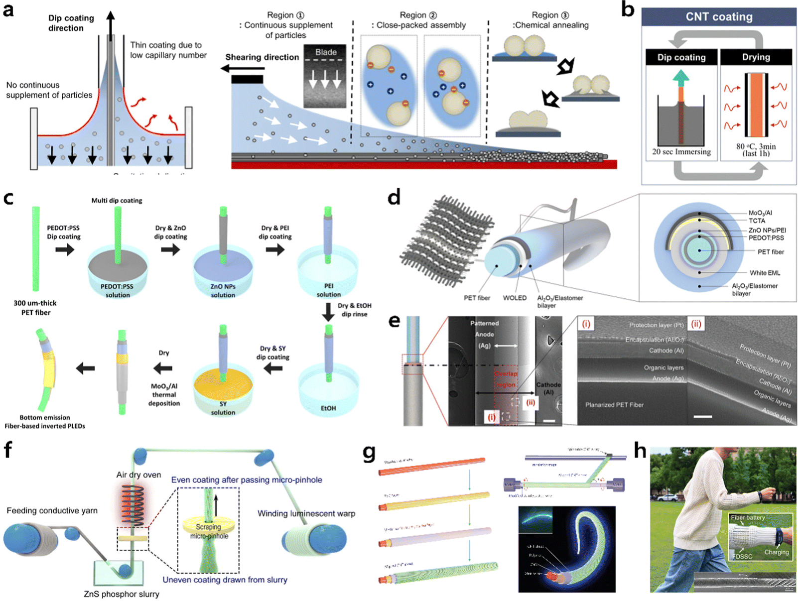 | ||
| Fig. 5 Dip coating methods. (a) Illustration of the dip-coating process showing particle distribution and chemical annealing for stable conductive coatings. Reproduced with permission.126 Copyright 2023, Springer Nature. (b) Schematic of CNT dip-coating and drying processes for hybrid strain sensing and load-bearing fibers. Reproduced with permission.124 Copyright 2019, John Wiley & Sons. (c) Scalable multi-step dip-coating fabrication of organic light-emitting diode (OLED) fibers. Reproduced with permission.125 Copyright 2017, American Chemical Society. (d) Schematic illustratoin of high-performance white OLED fibers. Reproduced with permission.127 Copyright 2021, John Wiley & Sons. (e) Cross-sectional structure of monorail fiber-based OLEDs with enhanced lifetime and performance for wearable displays. Reproduced with permission.128 Copyright 2023, John Wiley & Sons. (f) Large-area display textiles integrated with functional systems demonstrating uniform luminescence. Reproduced with permission.129 Copyright 2021, Springer Nature. (g) Fiber-shaped, weavable polymer light-emitting electrochemical cells with color-tunability. Reproduced with permission.130 Copyright 2015, Springer Nature. (h) Highly efficient fiber dye-sensitized solar cells with reflective hybrid counter electrodes for energy harvesting in wearable systems. Reproduced with permission.131 Copyright 2023, John Wiley & Sons. | ||
3.4. Chemical reduction methods
Chemical reduction methods are techniques used to synthesize or modify materials by reducing metal ions or compounds in a solution to their metallic or reduced forms through chemical reactions.132–134 Chemical reduction is primarily employed to introduce conductivity onto pre-existing fiber substrates, enabling the fabrication of fiber-based devices with enhanced electrical properties. In addition, the chemical reduction methods often involve adding a reducing agent (such as sodium borohydride, hydrazine, or ascorbic acid) to the metal salt solution, causing the metal ions to gain electrons and form metallic nanoparticles or thin films.96,134,135 Chemical reduction methods are widely employed to produce conductive materials by converting nonconductive substrates into conductive forms through the deposition of metallic nanoparticles. Consequently, chemical reduction methods are highly adaptable for fabricating conductive materials in various forms, including fiber structures, allowing for efficient and scalable processing.37,83–85,92–96 Furthermore, by varying the molecular weight of the solvent in the precursor solution, AgNPs were selectively formed on the outer shell of the spandex fibers, creating a percolated conductive network (Fig. 6a).84 As the molecular weight of the solvent increased, AgNPs were more selectively deposited on the outer shell of the fibers, significantly improving the electrical conductivity by facilitating a denser conductive network on the surface of fibers. In addition, the abundant formation of AgNPs on the outer shell of the fiber enabled the stretchable conductive fiber to withstand significant tensile strain while maintaining excellent stretchability. In addition to varying the molecular weight of the solvent in the precursor solution, the leaching process, which involves soaking the conductive fiber in pure solvents, was performed to optimize the distribution of Au ions on the fiber's surface (Fig. 6b).37 The leaching process effectively used osmotic pressure to position AuNPs on the outer shell while preserving the structural integrity of the polymeric core, enhancing mechanical flexibility. | ||
| Fig. 6 Chemical reduction methods. (a) Stretchable polymeric fibers with spatially controlled percolated Ag nanoparticle networks. Reproduced with permission.84 Copyright 2020, John Wiley & Sons. (b) Mechanical tissue-like elastomeric fiber electrodes embedded with Au nanoparticles for brain–machine interfaces. Reproduced with permission.37 Copyright 2022, John Wiley & Sons. (c) Highly conductive buckled shell-structured fibers offering strain insensitivity for wearable electronics. Reproduced with permission.136 Copyright 2022, American Chemical Society. (d) Stretchable Ag2Se thermoelectric fabric fabricated using a simple nonthermal approach for wearable electronics. Reproduced with permission.137 Copyright 2024 John Wiley & Sons. (e) Conductive fibers with strain-driven negative resistance switching, designed for healthcare monitoring with near-zero standby power. Reproduced with permission.138 Copyright 2023, John Wiley & Sons. | ||
Chemical reduction methods combined with structural modifications were used to create conductive fibers that maintain consistent conductivity even under mechanical deformation. Yoon et al. developed a conductive buckling fiber by embedding AgNPs into PU fibers using a buckled structure to enhance electrical and mechanical stability of fibers under strain (Fig. 6c).136 The prestrained PU fibers were immersed in an Ag precursor solution, followed by reduction using hydrazine hydrate to form AgNPs distributed throughout the fiber. The release of pre-strain induced compressive stress, creating buckled shell structures, which improved the strain insensitivity and conductivity while preventing delamination of the conductive shell. The buckling-based chemical reduction method enabled a high electrical conductivity (26![[thin space (1/6-em)]](https://www.rsc.org/images/entities/char_2009.gif) 128 S m−1) and excellent durability, maintaining performance under cyclic tensile strains. Kwon et al. developed stretchable thermoelectric fabrics by incorporating Ag2Se nanoparticles into cotton substrates (Fig. 6d).137 While conventional nanoparticles for thermoelectric devices often required thermal annealing, the incorporation of Ag2Se nanoparticles through chemical reduction methods eliminated the need for high-temperature treatment, ensuring compatibility with heat-sensitive polymers. The fabrication involved immersing the cotton fabrics in a precursor solution containing silver trifluoroacetate and sodium selenite, followed by rapid reduction using hydrazine hydrate, which facilitated the formation of dense Ag2Se nanoparticles within the fibers. The Ag2Se nanoparticle-based thermoelectric cotton fiber demonstrated exceptional durability under repeated mechanical deformations. Min et al. developed a strain-driven negative resistance switching of conductive fibers using chemical reduction and photocuring methods (Fig. 6e).138 The chemical reduction method was employed to synthesize AgNPs on PU-based stretchable fibers, enhancing electrical conductivity. To improve the mechanical properties and enable controlled cracking for sensor functionality, the fibers were encapsulated with an insulating layer of SU-8, an epoxy-based photoresist. Following ultraviolet irradiation, the SU-8 layer was selectively cured, resulting in uniform crack forming under strain. Pre-designed cracks enabled strain-dependent electrical switching, making the fibers suitable for textile-based healthcare applications.
128 S m−1) and excellent durability, maintaining performance under cyclic tensile strains. Kwon et al. developed stretchable thermoelectric fabrics by incorporating Ag2Se nanoparticles into cotton substrates (Fig. 6d).137 While conventional nanoparticles for thermoelectric devices often required thermal annealing, the incorporation of Ag2Se nanoparticles through chemical reduction methods eliminated the need for high-temperature treatment, ensuring compatibility with heat-sensitive polymers. The fabrication involved immersing the cotton fabrics in a precursor solution containing silver trifluoroacetate and sodium selenite, followed by rapid reduction using hydrazine hydrate, which facilitated the formation of dense Ag2Se nanoparticles within the fibers. The Ag2Se nanoparticle-based thermoelectric cotton fiber demonstrated exceptional durability under repeated mechanical deformations. Min et al. developed a strain-driven negative resistance switching of conductive fibers using chemical reduction and photocuring methods (Fig. 6e).138 The chemical reduction method was employed to synthesize AgNPs on PU-based stretchable fibers, enhancing electrical conductivity. To improve the mechanical properties and enable controlled cracking for sensor functionality, the fibers were encapsulated with an insulating layer of SU-8, an epoxy-based photoresist. Following ultraviolet irradiation, the SU-8 layer was selectively cured, resulting in uniform crack forming under strain. Pre-designed cracks enabled strain-dependent electrical switching, making the fibers suitable for textile-based healthcare applications.
4. Strategies for integrating neural modulation techniques with a fiber structure
4.1. Neural modulation methods for fiber-based neural interfaces
Various neural modulation technologies have been developed that can be integrated into fibers for use as neural interfaces. The fiber-based electrodes described in previous sections can be developed as neural interfaces integrated with multiple functionalities, such as electrical, optical, electrochemical, and other methods (Fig. 7). These electrodes record electrical signals from neuron activity, such as electrophysiological signals and local field potentials. For neural modulation using electrical stimulation, multiple fiber electrode arrays or textile-based integrations can be used. For optical functions, the optical fibers are combined with multielectrode arrays for real-time data acquisition and analysis. Optical waveguides are also fabricated with electrodes using a co-drawing fabrication process. Additionally, methods combining light sources with fiber devices have been developed. The electrochemical capabilities of fiber devices are achieved using microfluidic channels for drug delivery, ion-selective membrane coatings, and electrochemical techniques. Furthermore, future integration strategies, such as piezoelectric transduction and electromagnetic power, will support versatile applications, advancing the potential of fiber-based bioelectronics for neural interfaces. This section introduces the strategies through which various neural modulation techniques can be integrated into fiber electrodes, thereby demonstrating their potential as neural interfaces. | ||
| Fig. 7 Integration strategies of neural modulation techniques into the fiber for neural interfaces. Fibers with electrical function used in neural recording and stimulation are composed of a multiple fiber electrode array or a textile-based structure. Fibers with optical neural modulation include optical fiber combined with electrodes, co-drawing waveguides and electrodes, and LED-embedded fibers. Fibers with chemical function cover the fiber with a microfluidic channel for drug delivery, ion selective membranes, and electrochemical sensors. Other strategies include piezoelectric transduction, electromagnetic power and photo-related effects. | ||
4.2. Integration of electrical functionality
Electrical neural modulation is commonly used in brain–machine interfaces or implantable devices to restore sensory and motor functions.139 This method delivers electrical pulses through stimulating electrodes to specific areas of neural networks. Electrical stimulation can depolarize or hyperpolarize neurons by activating the charge distribution between the electrodes and neural interfaces. Fiber electrodes with conductive composites are usually used for neural signal recording owing to their low electrical impedance, controllable size, and minimally invasive nature.To achieve electrical stimulation with these fiber electrodes, a multiple fiber electrode array has been developed to modulate the nerve system, particularly for motor functions. For example, a bi-layer liquid metal particle (BiLMP)-based fiber thread device was developed for peripheral nerve stimulators (Fig. 8a).126 To enhance the targeting and signal quality of the BiLMP fiber threads, they were designed as bipolar stimulators connected to the sciatic nerve of mice. This setup allows for stimulation of the muscular nerve and measurement of electromyography (EMG) signals. Bi et al. conducted chronopotentiometry using MXene fiber electrodes, where a charge can be injected into the fiber electrodes through biphasic, charge-balanced current pulses. In vivo electrophysiological tests were conducted by implanting a bipolar assembly of MXene fiber electrodes on the sciatic nerve of a rat to deliver current pulses for electrical stimulation (Fig. 8b).140 The peak-to-peak amplitude of the evoked EMG signal increased as the amplitude of the electrical stimulation current on the sciatic nerve was increased. The use of multiple fiber electrodes knotted on specific nerves facilitates efficient electrical stimulation and EMG signal measurement.
 | ||
| Fig. 8 Integration of electrical functionality into fiber electrodes. (a) Schematic (left) and image (right) of the knotted fiber-based electrical stimulation thread implanted in the sciatic nerve. Reproduced with permission.126 Copyright 2023, Springer Nature. (b) Schematic of in vivo stimulation and recording with a pair of fiber electrodes implanted in the sciatic nerve. A representative evoked electromyography (EMG) potential induced by electrical stimulation of the fiber electrodes. Reproduced with permission.140 Copyright 2024, American Chemical Society. (c) Schematic (left) and image (right) of the graphene bipolar fiber electrodes for deep brain stimulation. Reproduced with permission.141 Copyright 2020, Springer Nature. (d) SEM image of CNT electrodes fabricated by twisting single filaments. The shaded area of the cyclic voltammogram of the CNT fiber shows the charge storage capacity related to electrical stimulation. Reproduced with permission.142 Copyright 2015, American Chemical Society. (e) Images of the covered stimulus cuff electrode and recording nanofiber-based electrode. The evoked neural signal is recorded by the nanofiber electrode. Reproduced with permission.143 Copyright 2017, American Chemical Society. (f) Schematic of the electrical stimulation setup for measuring the EMG signal associated with a stimulated tibial nerve of the lower limb. Signals are recorded by the textile electrodes during plantar-flexion contraction. Reproduced with permission.144 Copyright 2016, John Wiley & Sons. | ||
Bipolar fiber electrodes enable effective DBS to modulate neuronal circuits, particularly in treating movement disorders like PD. Fig. 8c shows graphene fiber microelectrodes used in a PD rat model with simultaneous DBS and functional magnetic resonance imaging.141 For the bipolar fiber structure, individual graphene fibers were insulated with a 5 μm-thick parylene-C film. The fibers were parallelly aligned and bonded with the glue. After soldering the stimulation pulse generator, the bipolar graphene fiber system was prepared for DBS targeting the subthalamic nucleus. Similar to graphene, CNTs show high mechanical strength and electrical conductivity, making them suitable for brain neural stimulation and recording. Fig. 8d shows a high-performance CNT fiber microelectrode capable of detecting single neuronal units for electrical stimulation therapy in the brain.142 The individual CNT fibers were coated with a polystyrene-b-polybutadiene (PS-b-PBD) copolymer for insulation, and then assembled into bipolar fiber microelectrodes by twisting the individual fiber on a commercial assembly station. The bipolar CNT fiber system demonstrated a charge injection capacity of ∼372 mC cm−2, indicating that the maximum charge for electrical stimulation is 2 to 3 orders of magnitude higher than those of other materials.
Fiber electrodes can also be effectively integrated into 2D structures, providing unique advantages such as conformal contact with biological tissues and geometrically customized shapes for wearable devices. Nanofiber membranes fabricated using the spinning process are emerging as a promising candidate for constructing 2D fiber electrodes. These membranes offer several advantages, including their biocompatibility, flexibility, and an excellent surface area-to-volume ratio, which are critical for effective neural interfacing and signal acquisition. Inkjet printing onto polyimide (PI) nanofiber membranes was used to pattern the recording electrodes simply (Fig. 8e).143 Conductive composites can be easily printed on PI nanofiber membranes with high resolutions (∼304.8 μm) and show a low sheet resistance of ∼0.31 Ω sq−1 for repeated printing. The properties of the nanofiber membranes, such as the locking structure and holes, allow the nanofiber-based electrodes to conform to peripheral nerve tissue. Without implantation, the 2D fiber electrodes can also serve as peripheral neural stimulators when attached to the skin. For example, conducting polymer-coated textiles were evaluated for their ability to monitor muscle activity and stimulate the tibial nerve for neuromuscular responses (Fig. 8f).144 Coating a conductive composite on the textile surface is also a simple and brief method to construct electrical networks on fiber structures. In this study, a PDMS-based protective layer was used to pattern a highly conductive PEDOT:PSS solution onto the textile, enabling seamless integration between the conductive solution and textile structure. The fabricated textile electrodes with the ionic liquid gel to improve interfacial contact between the skin and electrodes were demonstrated as a wearable transcutaneous EMG device for muscle activity monitoring and injured muscle rehabilitation.
4.3. Integration of optical functionality
Optogenetics, which uses optical modulation in neurons for precise control of neuronal activities, enables selective stimulation and inhibition of specific neurons in biological tissues by delivering light at particular wavelengths to targeted areas of the nervous system. Techniques for recording and modulating optical signals have been developed to manipulate neural circuits with high accuracy, minimal invasiveness, and precision control over individual neurons. In particular, optical stimulation in the nervous system has advantages such as the ability to target specific neurons for their selective activation without affecting surrounding neurons, and wavelength flexibility that allows simultaneous modulation of multiple neuronal populations.Fiber-based devices that integrate optical functions have been developed by combining flexible optical waveguides with microelectrode arrays. The key factors of integration strategies include decreasing the assembly volume of the optical fiber and electrodes, maintaining an elastic modulus similar to tissue (e.g., brain tissue about 1–10 kPa), and ensuring consistent performance during chronic recording and modulation. For instance, a silk-optrode, an optoelectronic probe was developed by attaching a natural silk-based waveguide to a flexible electrode array (Fig. 9a).145 The 128-channel microelectrodes were designed to be approximately two orders of magnitude smaller than the silk-based waveguide, ensuring that the integrated fiber devices did not notably increase the fiber diameter. A prefabricated mold was used to align the flexible electrode array with the central axis of the silk optical fiber under a microscope. The silk material was also used as a bio-glue to fix the flexible electrode array radially to the silk optical fiber. In addition, highly stretchable optical probes with a low elastic modulus were developed using an alginate-polyacrylamide (PAAm) hydrogel optical fiber (Fig. 9b).146 The PAAm-based hydrogel addresses the limitations of traditional hydrogel optical fibers, such as poor sustainability in neural tissue, mechanical mismatch-induced elimination, and potential to waveguide propagation loss in highly stretched states. The optimized hydrogel optical fiber, composed of 40% Aam, showed a low Young's modulus (∼60 kPa) and a low propagation loss (0.249 dB cm−1). For integration into the hydrogel-optrode array, the hydrogel optical fiber was dehydrated to increase stiffness and then threaded through a ceramic ferrule and a silica tube with tetrodes. The electrode connector stabilized this tube and ferrule using epoxy resin. The co-drawing technique, including the thermal drawing process, offers a promising method for integrating optical waveguides with electrodes to fabricate fiber-based neural devices. For example, thermal drawing enables the incorporation of neural recording electrodes with drug delivery channels or optical waveguides within the same fiber. This innovative strategy addresses limitations in traditional methods of combining optical fibers and electrodes, such as alignment issues and structural flexibility. In the conventional thermal drawn process, materials are fabricated into optical probes embedded inside polymer-based optical waveguides and metal electrodes. To improve optical properties and flexibility, a double-clad waveguide was employed in the inner core, with the metal electrodes located in the outer part of the fiber (Fig. 9c).147 This combined constant-scale and scale-down co-drawing allowed the integration of optical fibers and metal electrodes into a flexible multimodal fiber probe. The core materials, polycarbonate (PC), polyvinylidene fluoride, and polymethyl methacrylate, were used to form the waveguide with efficient light confinement. The metal electrodes, such as Pt and Au, were embedded in the outer layer for neural signal recording. However, embedding solid metal electrodes can create a rigid configuration that disturbs the flexibility and stretchability of fibers, causing a mechanical mismatch between the fiber probes and neural tissue. Fig. 9d shows a fiber probe combining thermally drawn optical fiber and conductive AgNWs through dip-coating.119 These two combined techniques, thermal drawing, and dip-coating, were used to integrate the optical fibers and electrodes for electrophysiological recording and optical neuromodulation. The optical fiber, composed of PC as the core and cyclic olefin copolymer (COC) as the cladding, had an AgNW mesh uniformly deposited on the COC cladding layer. In this process, the AgNWs were dispersed in isopropyl alcohol (IPA) and applied to the fiber surface via dip coating, ensuring uniform deposition. This resulted in fiber probes with an AgNW mesh that were more flexible and stretchable than those with embedded metallic electrodes. In addition, the micrometer-thick AgNW mesh coating ensured a minimal increase in the probe diameter.
 | ||
| Fig. 9 Integration of optical functionality in fiber electrodes. (a) Schematic (left) and image (right) of a silk optical waveguide with a microelectrode array. Reproduced with permission.145 Copyright 2023, Springer Nature. (b) Schematic and image of the hydrogel optical fiber-coupled electrode array, with evoked potential recorded using the hydrogel-optrode array following optical stimulation. Reproduced with permission.146 Copyright 2018, John Wiley & Sons. (c) Images and corresponding element mapping of multimodal fibers for optical stimulation and signal recording at various optical frequencies. Reproduced with permission.147 Copyright 2020, John Wiley & Sons. (d) Illustration of the fiber dip-coating process with AgNWs. Reproduced with permission.119 Copyright 2017, American Association for the Advancement of Science. (e) Schematic of electroluminescent fiber structures with hydrogel electrodes and brain-interfaced camouflage of the fiber under green light. Reproduced with permission.148 Copyright 2018, John Wiley & Sons. (f) Schematic (left) and image (right) of the multisite optical stimulation fiber with mini-LEDs. Reproduced with permission.149 Copyright 2019, Springer Nature. | ||
Another strategy for coordinating the optical and conductive functions in neuromodulation is to fabricate fiber probes that integrate light sources and electrodes. Direct integration of light sources into fiber structures eliminates structural complexity, reduces potential losses from waveguides, and enhances flexibility in the implanted direction of the fiber probes. For example, electroluminescent fibers were developed using a continuous one-step extruding method (Fig. 9e).148 Two hydrogel electrodes were embedded parallel to the electroluminescent layer, generating light with low power consumption (10.5 mW at an electrical field of 2.3 V μm−1). These electroluminescent fibers were demonstrated for use in human–machine interfaces, mimicking the color-changing ability of chameleons. Moreover, this method enables selective optical stimulation of target neural regions. For example, by controlling the voltage applied to different segments of the fiber, specific sections can light up independently, allowing spatially targeted neural stimulation. In addition, a spiral shape-memory fiber-based optical stimulation device was developed for the selective stimulation of nerves by separating the stimulation sites (Fig. 9f).149 The shape-memory polymer adapts to nerve bundles owing to its high mechanical flexibility. Multiple mini-LEDs were affixed to a PU fiber, which was shaped into a spiral to conform to cuff-like structures. The mini-LEDs were embedded in the PU fiber with epoxy resin adhesive, controlling the distance and angle to target the nerve. This direct mini-LED integration strategy avoids the complexity and propagation loss of traditional optical waveguides and allows the selective activation of distinct neural regions with high spatial precision.
4.4. Integration of chemical functionality
Emerging neural interfaces for chemical modulation, such as drug delivery or electrochemical detection, usually incorporate microfluidic channels, micropumps, or electrochemical sensors to control and measure signals from target neural tissue. These systems are designed to locally deliver drugs, reducing side effects and allowing for targeted modulation of neural activity. Microfluidic channels are commonly employed in small, flexible probes to transport drugs or biomolecules to the nervous system. Recent advancements aim to integrate microfluidic channels into fiber-based devices in a highly integrated, minimally invasive format. For example, a novel miniaturized rotational thermal drawing process (mini-rTDP) was developed for fabricating miniaturized fibers (Fig. 10a).150 The twisted 3D spiral channel-embedded fiber structures were fabricated by controlling key parameters such as spiral radius, cross-sectional geometries, and pitch of the spiral fiber. These features enable the integration of multiple microfluidic channels within a fiber structure. Moreover, the 3D spiral microfluidic channels within fiber structures have the potential for repositioning particles or cells within a fluid medium, benefiting biomedical applications. However, previous thermally drawn microfluidic fibers were restricted to drug release at the fiber tip only. To overcome this limitation, a laser method for multisite interfaces within each fiber device was developed (Fig. 10b).151 A femtosecond laser micromachining technique was used to expose electrode recording sites and microfluidic channel openings for recording and drug releases. By focusing the laser beam on specific areas of the thermally drawn fibers, polymer-based materials were selectively evaporated within the focal zone, allowing for microchannel formation at any desired location. Each of the four microfluidic channels of the fiber showed the delivery of four different colored fluids along the fiber at different depths. | ||
| Fig. 10 Integration of chemical functionality in fiber electrodes. (a) Illustration and image of the microchannel created using the rotational thermal drawing process. Reproduced with permission.150 Copyright 2024, Springer Nature. (b) Schematic of exposing microfluidic holes and electrodes on the fiber, with four microfluidic holes fabricated on the fiber as shown in optical and SEM images. Reproduced with permission.151 Copyright 2020, Springer Nature. (c) Structure of single-ply sensing fibers (SSFs) and the combined multiply sensing fiber (MSF) composed of four different SSFs. Reproduced with permission.152 Copyright 2020, Springer Nature. (d) Schematic of the working principle of the fiber potassium ion sensor. Reproduced with permission.153 Copyright 2024, John Wiley & Sons. (e) Schematic of a biodegradable fiber calcium ion sensor and its degradation process. Reproduced with permission.154 Copyright 2024, John Wiley & Sons. (f) Schematic of a multifiber microarray for tracking extracellular calcium ions. Reproduced with permission.155 Copyright 2021, John Wiley & Sons. (g) Schematic of a microsensor composed of carbon fibers and epoxy, with the voltammetric signal recorded in response to stimulation, using the microsensor. Reproduced with permission.156 Copyright 2020, Springer Nature. (h) Illustration of dopamine sensing via fast scan cyclic voltammetry (FSCV) using a structurally aligned multifunctional neural probe. Reproduced with permission.157 Copyright 2024, John Wiley & Sons. | ||
In electrochemical modulation, interface modifications that enhance electrochemical stability and control the release of ions or reactive species between electrodes and neural tissue have been developed using nanoscale structures such as conductive polymers or metal nanostructures. These interfaces can stimulate neurotransmitter release, modulate local pH, or modify neural cell membranes, thereby affecting neuron signals. In particular, implantable electrochemical sensors offer an effective platform for in vivo monitoring of neurochemicals. A novel strategy for modifying the interface of electrochemical sensors for in vivo monitoring involves the use of ionophore-based ion-selective membranes (ISMs). ISMs selectively filter specific ions from a mixed electrolyte, enabling potential remote refilling by drawing ions back into an internal reservoir after each delivery cycle. To integrate with fiber structures, flexible fiber-based implantable electrochemical sensors have been developed by twisting CNTs to resemble muscle filaments and coating them with ISMs (Fig. 10c).152 They fabricated single sensing fibers for detecting hydrogen peroxide (H2O2), glucose, and ions (Na+, Ca2+, and K+) by incorporating different specific detection components. These single-sensing fibers were twisted into hierarchical and helical assemblies to detect multiple electrochemical biomarkers. The ISMs were applied to CNT fibers via dip-coating the ISM cocktail, forming a specific ion-adsorptive layer. Owing to their high surface roughness, large contact area, and excellent electrochemical properties, CNT fibers are easily modified with other components. In addition, a fiber-based potassium ion sensor was developed for stable, long-term, and real-time monitoring of ions in vivo (Fig. 10d).153 This fiber sensor is composed of a conductive CNT fiber coated with a potassium ISM and interfaces through a hydrophobic transduction layer, enhancing the durability and stability of electrochemical properties in an aqueous environment. The CNT fiber, with a high surface roughness (∼10.6 nm) and hydrophobic-treated PEDOT:PSS as a transduction layer, showed a high peeling force of 131.58 mJ m−2 with a K+-selective membrane, outperforming previous research. This technique established stable performance between the potassium ISM and the transduction layer, ensuring their robust contact for long-term in vivo electrochemical signal measurements. A biodegradable fiber ion sensor was also designed for short-term therapeutic applications (Fig. 10e).154 This biodegradable fiber sensor utilized calcium ionophores covalently bonded to bioinert AuNPs, which formed an ion-selective membrane replacing the previous sensor. The main substrate of the fiber was collagen, with a conductive Au layer and a capacitive polypyrrole (PPy) layer. The AuNPs electrodeposited on the fiber surface were bound to Ca2+ ionophores through Au–C bonds between the Au and acetylene-terminated groups. The sensor degraded within approximately four weeks in vivo, providing accurate ion measurements as the Ca2+ ionophores remained stably immobilized on the AuNPs. Another ion sensor integration method is shown in Fig. 10f. For real-time extracellular Ca2+ monitoring, a new anti-fouling microfiber array was designed with high selectivity and reversibility.155 The basic structure of the fiber core was carbon and Au particles, wrapped with graphene oxide microbands for anti-fouling effects. The Au particles wrapped by graphene oxide created active sites for precise attachment of Ca2+ recognition molecules. With three kinds of Ca2+ ligands, the fiber demonstrated both high selectivity and reversibility, enabling real-time Ca2+ monitoring for over 60 days.
The fast scan cyclic voltammetry (FSCV) method, combined with carbon-based fiber microelectrodes, is widely used for detecting neurotransmitters, hormones, and metabolites in biological systems. FSCV enables rapid scanning of electrical potentials, generating cyclic voltammograms that capture real-time changes in neurotransmitter concentrations with subsecond accuracy. When combined with fiber structures, this technique offers high spatiotemporal resolution, chemical specificity, and minimal invasiveness. Dopamine is a representative neurotransmitter detected via FSCV owing to the high temporal resolution of FSCV, which allows for subsecond detection and differentiation of dopamine from other substances in the brain. For example, a 7 μm diameter carbon nanofiber microsensor was developed as a biocompatible FSCV sensor for long-term implantation in target tissue (Fig. 10g).156 This fiber electrode integration minimizes tissue disruption while maintaining sensitivity to dopamine. Immunostaining confirmed minimal glial encapsulation and interference at the fiber site. Fig. 10h shows a novel fiber probe with forest-drawn CNT sheets wrapped around thermally drawn polymer fibers using a direct wrapping process.157 This CNT-wrapped fiber supports FSCV and enhances the electrochemical performance of FSCV owing to the high electron transfer rate of the aligned CNT sheets. Additionally, the anisotropic conductivity along the fiber length improves signal fidelity while ensuring the structural flexibility of the fiber.
4.5. Additional integration strategies for future neural interfaces
Future neural interfaces should aim to revolutionize neuroscience and clinical treatments by addressing the limitations of traditional methods, such as nonimmunogenic delivery, limited spatiotemporal precision, and long-term safety. Previous implantable fiber neural interfaces mostly allowed electrical, optical, and chemical neural modulation in the neural system. Emerging technologies such as mechanical, piezoelectric, and electromagnetic forces exhibit promise as neural modulation methods by providing minimally invasive, precise resolution, and adaptable neural modulation capabilities. For example, miniaturized piezoelectric devices, such as implantable ultrasound stimulators, utilize flexible piezoelectric elements to generate localized ultrasonic waves for DBS (Fig. 11a).158 The ultrasound transducer was fabricated at the micron-scale (30 μm thick, total diameter of 140 μm) through an elaborate photolithography process. This method enables precise modulation to detect neurons close to the device without genetic alteration, addressing challenges such as poor spatial resolution and tissue scattering in traditional ultrasound methods. Another potential application of piezoelectric methods in neural interfaces is nerve regeneration. Electroactive scaffolds composed of piezoelectric biomaterials show notable promise in regenerating damaged peripheral nerves. Previous studies have shown that electrical stimulation can enhance the regeneration of peripheral nerves. To reduce infection and inflammation, the integration of nanofiber-based porous scaffolds with piezoelectric biomaterials has been developed to provide electrical generation function without harming tissue. For instance, an ultrasound-driven electrical stimulator with a biodegradable 3D piezoelectric scaffold was developed to repair spinal cord injuries (Fig. 11b).159 The integration strategy included (1) PLA-based electrospun nanofibers, (2) incorporation of biodegradable piezoelectric nanowires, and (3) a remote, wireless, and programable ultrasound transducer. In particular, the electrospun nanofibers, composed of piezoelectric nanowires and PLA, were fabricated into a 3D scaffold using a rolling-up process with 3D-printed PLA microchannels. Upon ultrasound irradiation, the scaffold accelerated electrical output, facilitating spinal cord injury repair. This nanofiber-based technique also promotes rapid regeneration in the peripheral nerve system. Aligned polycaprolactone (PCL) nanofiber nerve conduits, combined with piezoelectric zinc oxide (ZnO) nanoparticles, were developed via electrospinning (Fig. 11c).160 To prepare the mixed solution of ZnO and PCL, ZnO was first dissolved in hexafluoro isopropanol, followed by the addition of PCL. The nanofiber mats were electrospun from the mixed solution, suitable for this fabrication process. The ZnO nanoparticles imparted piezoelectric properties to the fibers, generating endogenous electrical stimulation under mechanical deformation. In addition, the aligned nanofiber morphology promoted directed growth of axons, ensuring effective reconnection of the nerve tissue. | ||
| Fig. 11 Integration of various modulations in fiber electrodes. (a) Schematic (left) and image (right) of an implantable piezoelectric ultrasound stimulator. Reproduced with permission.158 Copyright 2024, Springer Nature. (b) Illustration of ultrasound-powered wireless 3D piezoelectric scaffolds for spinal cord injury repair. Reproduced with permission.159 Copyright 2022, American Chemical Society. (c) Schematic of an electrospun nanofiber mat applied to the sciatic nerve. Reproduced with permission.160 Copyright 2022, Elsevier. (d) Schematic of a soft magnetic fiber with microbubbles and nanomagnets. Reproduced with permission.161 Copyright 2021, Springer Nature. (e) Image of a flexible magnetic liquid metal-based fiber. Reproduced with permission.162 Copyright 2024, American Chemical Society. (f) Illustration of a neural stimulation patch applied to targeted nerve bundles. Reproduced with permission.163 Copyright 2023, Springer Nature. (g) Schematic of electromagnetic induction in a hollow fiber for releasing the nerve growth factor. Reproduced with permission.164 Copyright 2021, Elsevier. (h) Schematic of a multifunctional bidirectional fiber-based optoacoustic emitter. Reproduced with permission.165 Copyright 2023, John Wiley & Sons. (i) Schematic of acoustic wave stimulation and representative waveform recorded using a transducer. Reproduced with permission.166 Copyright 2020, Springer Nature. (j) Schematic diagram of a carbon fiber-based photostimulator. SD projection image showing 30-second pre- and post-stimulation calcium traces in response to 1-second photostimulation. Reproduced with permission.167 Copyright 2024, John Wiley & Sons. | ||
To improve the secretion of nerve growth factors, electromotive forces controlled by magnetic fields have been studied for synergistic therapy. These electromagnetic forces can be employed through fiber-based systems that integrate conductive and magnetic components. Electromagnetic fibers, incorporating novel materials such as magnetic cores or magnetostrictive polymers, efficiently induce electromagnetic induction and offer biocompatibility for wireless neural stimulation and guidance of neural growth. These systems can also aid non-invasive peripheral nerve repair by generating electrical currents through magnetic fields. Fig. 11d shows a soft magnetic fiber, where the magnetic dipole alignment induces a strong magneto-mechanical effect.161 The manipulated magnetic dipole–dipole interaction in the fiber demonstrated the potential for achieving a low elastic modulus (∼630 kPa) and a pressure that needs to deform the fiber (∼450 kPa), suitable for human activities. The magnetoelastic effect was integrated into the fiber structure by embedding solid nanomagnets in a soft silicone polymer matrix during a mechanical extrusion process. These microbubbles improved the stretchability of the fiber and formed nanoscale-to-microscale cavities in the fiber structure, improving its sensitivity to mechanical deformation. The fiber demonstrated a notable magnetoelastic effect, with magnetic dipole alignment in the nanomagnets after magnetization in an impulse magnetic field. Similarly, an elastic electromagnetic fiber with a magnetic liquid metal (MLM) was developed using an ionic chelation strategy (Fig. 11e).162 The MLM core, composed of a gallium-based LM mixed with iron particles, was encapsulated in a sheath fabricated using waterborne polyurethane and sodium alginate. The ionic chelation between calcium ions and carboxyl groups in the sheath materials ensured robust mechanical integrity and continuous fabrication of the fiber. These fibers converted mechanical deformations into variations in the magnetic field.
The electromagnetic effect can be integrated into fiber structures by embedding magnetic materials or incorporating aligned magnetic nanostructures within the nanofiber mats. For example, a wireless electromagnetic stimulation patch was fabricated using a melt-electrowriting (MEW) process (Fig. 11f).163 The MEW process printed biocompatible, biodegradable PCL nanofibers into anisotropic structures, which were then coated with Au through glancing angle deposition. The Au-coated nanofibers effectively converted electromagnetic induction into electrical currents, serving as energy-harvesting components. In addition, these currents were used for wireless electromagnetic stimulation to direct interaction with neural cells. This flexible, wireless nanofiber patch with anisotropic structures demonstrates that the electromagnetic effect can provide precise, non-invasive power to neural tissue. Fig. 11g shows size-tunable microfluidic hollow fibers that can generate electromotive forces through a pulsed magnetic field.164 Composed of sodium alginate, polyacrylamide (PA), and PPy, the hollow fibers provide enhanced conductivity for generating electromotive forces controlled via the pulsed magnetic field. These materials were integrated into a hollow fiber structure using a coaxial microfluidic spinning process, where a solution containing sodium alginate, PA, PPy, and a photoinitiator was extruded through the outer nozzle, while a calcium chloride solution was simultaneously introduced through the inner nozzle. This multinetwork strategy produced a composite hollow fiber with tunable mechanical properties, improved elasticity, and high electrical conductivity.
In terms of transducers that convert optical energy to mechanical energy, the photoacoustic technique offers remarkable potential for neural modulation applications. Through the photoacoustic effect, pulsed laser energy absorbed by a specially designed material coating generates acoustic waves that can stimulate neurons with high spatial precision and without genetic modification. The integration of the photoacoustic method into fiber structures offers several advantages in the fiber composition. This method enables the transfer of localized ultrasound at the fiber tip, stimulating target tissue while maintaining biocompatibility and flexibility comparable to those of neurons. For example, a multifunctional photoacoustic fiber was used for both neural modulation and electrophysiological recording (Fig. 11h).165 Similar to optical integration strategies, an optical waveguide and multiple electrodes were thermally drawn into a single fiber. The difference is that a photoacoustic coating composed of carbon black and PDMS was deposited at the end of the waveguide, generating pressure. When the laser pulses were delivered through the coated waveguide, the photoacoustic coating induced rapid thermal expansion, generating acoustic waves at ultrasound frequencies. This function provided highly localized mechanical stimulation suitable for neural modulation. In addition, a miniaturized fiber photoacoustic converter was developed for spatially elaborate photoacoustic neural modulation (Fig. 11i).166 The fiber serves as a multimodal optical fiber with a 200 μm core diameter, and its tip was coated with a two-layer nanocomposite. The first layer of diffusion, a ZnO nanoparticle–epoxy mixture, uniformly scattered the incoming laser light omnidirectionally, while the second layer composed of graphite powder and epoxy converted the scattered laser energy into thermal energy. The rapid heating and thermal expansion of the surrounding epoxy material generated acoustic waves at ultrasonic frequencies (1–5 MHz).
A novel photoelectric neurostimulation method has gained high attention for its potential to overcome limitations in therapeutic and bioelectric applications. This technique generates electrical pulses converted from near-infrared light, enabling neural tissue stimulation without genetic alterations. The photoelectric effect was integrated into the fiber structure using ultrasmall carbon electrodes with innovative insulation and coating techniques (Fig. 11j).167 A carbon fiber, encapsulated in Parylene-C except for the tip, served as the conductive base for precise neural interaction. To enhance the photoelectric conversion efficiency of the fiber, a photovoltaic polymer blend of poly(3-hexylthiophene) and [6,6]-phenyl C61-butyric acid methyl ester was dip-coated onto the electrode and cured at high temperatures. These photovoltaic materials considerably increased charge storage capacity and decreased the impedance of the electrode, improving its ability to generate voltages under laser photo-stimulation.
5. Applications of fiber-based neural interfaces
Fiber-based devices in neural interfaces have emerged as highly effective candidates, offering innovative solutions through specialized fiber fabrication processes with conductive composites and neural modulation functionalities. Their exceptional flexibility and minimally invasive design enable precise stimulation of target neural regions and accurate measurement of electrophysiological signals. Owing to their versatility, these devices have been validated in both the central and peripheral nervous systems for therapeutic applications. In particular, fiber-based devices designed for the brain, spinal cord, and motor neuron-related nervous system—particularly those associated with regions prone to chronic diseases—are highlighted for their potential in treatment. Herein, fiber-based neural interfaces for the brain, spinal cord, and motor-related nervous system are discussed, focusing on their functional contributions to region-specific measurements, neural tissue regeneration, and long-term in vivo accessibility.5.1. Brain–machine interfaces
Fiber-based neural interfaces for the brain are promising devices for future brain–machine interfaces aimed at understanding and treating neurological disorders in the brain. Their design allows them to navigate deep neural tissues while minimizing damage and immune responses. In addition, they can be integrated with cutting-edge technologies for targeting specific brain regions with high spatial and temporal resolution. By employing various modalities for neural modulation, these devices offer novel avenues for electrophysiological signal mapping and neural circuit modulation, enabling therapeutic interventions for chronic brain diseases such as PD, epilepsy, and cognitive impairments. For example, spatially expandable fiber probes have been validated for recording brain activities, stimulating via an optical laser, and delivering chemicals into the deep brain (Fig. 12a).151 The fiber probe measured burst-suppression voltage spikes under different levels of anesthesia (0.5% and 2% isoflurane) from implanted electrodes. In the thalamus region of mice, optically evoked neural activities caused by a laser through one waveguide in the fiber were detected by four electrodes in the fiber probe. No optically evoked neural signals were observed when a synaptic blocker was injected into the target thalamus region. Another thermally drawn fiber probe designed for micro infusions of γ-aminobutyric acid (GABA) in rodents and nonhuman primates is shown in Fig. 12b.168 This fiber probe, with two microfluidic paths and four microelectrodes, delivered GABA to the premotor cortex of a nonhuman primate, rhesus macaque, while measuring neuron activities. It demonstrated the delivery of GABA and recording of neuron activities in the putamen, a deep brain structure related to reward-meditated learning and memory. By modulating receptor-specific neural activity, this device provided insights into the neural basis of working memory and motor control. To validate the therapeutic capacity of a fiber device in PD models, fiber microelectrodes fabricated using graphene were used for effective DBS (Fig. 12c).141 The PD rats were prepared by injecting neurotoxin 6-hydroxydopamine that caused a loss of dopamine neurons in the brain of rats. The effect of DBS using the graphene fibers was demonstrated by comparison to the time spent in mobility of PD rats when DBS was turned on and turned off (pre-DBS and post-DBS). | ||
| Fig. 12 Fiber-based neural interfaces in the central nervous system; brain–machine interfaces. (a) Electrophysiological recordings from the spatially expanded multimodal fiber probe during optical stimulation. Reproduced with permission.151 Copyright 2020, Springer Nature. (b) Magnetic resonance imaging (MRI) of the brain implanted with the fiber probe. Single-unit firing rate recorded in response to γ-aminobutyric acid (GABA) infusion. Reproduced with permission.168 Copyright 2023, American Association for the Advancement of Science. (c) Locomotor activities measured in the hemi-Parkinsonian rats using graphene bipolar stimulating fibers. Reproduced with permission.141 Copyright 2020, Springer Nature. (d) Schematic and image of electrophysiological signal recordings over four months from the AuNP fiber probe. Reproduced with permission.37 Copyright 2022, John Wiley & Sons. (e) Photograph of the implanted SAMP over one year and the averaged signals of extracted spikes. Reproduced with permission.157 Copyright 2024, John Wiley & Sons. (f) Photographs of the microfiber-shaped neural probes in dry and wet states and recorded endogenous neural activities from the brain. Reproduced with permission.169 Copyright 2020, Royal Society of Chemistry. (g) Cross-sectional schematic of multifunctional hydrogel neural interfaces assembled with waveguide, electrodes, and microfluidic channel. Reproduced with permission.170 Copyright 2021, American Chemical Society. (h) Schematic illustration of the multifunction fiber for synaptic interaction, signal detection, and stimulation of both chemical and electrophysiological signals. Reproduced with permission.171 Copyright 2024, American Chemical Society. (i) Schematic of microelectronic-integrated multifunctional fibers with optogenetics, electrophysiology, fluidic delivery, and thermometry. Optically evoked electrophysiological signals and chemically induced brain hypothermia recorded by the fiber. Reproduced with permission.32 Copyright 2024, Springer Nature. | ||
Fiber-based probes, designed to address challenges in long-term brain–machine interfaces, minimize FBRs and mechanical mismatch with brain tissues, enabling stable, high-quality neural recordings over extended periods. For example, an AuNP-embedded fiber probe combines mechanical properties similar to those of tissues (Young's modulus of 170 kPa; bending stiffness of 2.2 N m−1) with high electrical conductivity (∼7.68 × 10⁴ S m−1), achieving chronic stability in vivo (Fig. 12d).37 The AuNP fiber probe recorded single-unit action potentials for up to four months with stable signal-to-noise (SNR) levels while tracking the same neural spikes. Compared to conventional metal wire probes, the AuNP fiber probe elicited a substantially lower chronic immune response in vivo. Moreover, a multifunctional fiber probe demonstrated prolonged chronic recording for over a year (Fig. 12e).157 Throughout the year, the implanted multifunctional fiber probe showed no evident degradation or structural deformation while monitoring evoked spikes. Single-unit activities recorded at 1-month intervals maintained a high SNR range of 8 to 12 during a year. To enable chronic neural interfacing, a technique was developed to adjust the elastic modulus of the fibers by altering hydration (Fig. 12f).169 A CNT fiber with calcium-crosslinked sodium alginate exhibited an elastic modulus change from 10 GPa (dry state) to 10 kPa (wet state) when it was implanted in the brain, which was similar to that of the brain tissue. In the wet state, the fiber probe recorded single-unit activities for four weeks of continuous monitoring with minimal inflammatory responses.
Multifunctional fiber probes in brain–machine interfaces enable simultaneous neural modulation by integrating multiple modalities into a compact and flexible form. These advanced neural probes provide unparalleled capabilities for understanding complex brain circuits and developing therapeutic strategies for neurological disorders. For instance, a multifunctional hydrogel-based fiber could transmit drugs, deliver optical stimulation, and measure electrophysiological signals in the brain (Fig. 12g).170 Using a solvent evaporation or entrapment-driven integration process, each component was incorporated with water-responsive hydrogels without producing any toxic byproducts. The developed fiber probe was demonstrated in the nucleus accumbens, associated with reward and motivation pathways, with optogenetic stimulation, electrophysiological recording, and targeted drug delivery. For bidirectional communication of synaptic activities, an electrophysiological and chemical multifunctional fiber probe was developed through the co-drawing thermal process (Fig. 12h).171 This probe combined four modalities: chemical signal sensing (dopamine), chemical interrogation (nomifensine, a dopamine reuptake inhibitor), optical stimulation, and electrophysiological recording in the ventral tegmental area (VTA), linked to various behaviors. Furthermore, solid-state microelectronic components were integrated into polymer-based fibers for multifunctional bioelectronic interfaces (Fig. 12i).32 The multifunctional fiber, composed of μLEDs, microfluidic channels, and thermal sensors, enables wireless, programable neural modulation. Designed for implantation in brain nuclei such as VTA, the fiber facilitates spontaneous optical modulation, evoking neural activity recording, and thermometry in the brain region.
5.2. Spinal cord modulation
Spinal cord modulation is a form of neuromodulation involving the surgical implantation of electrodes to alter nervous system activity. These implanted electrodes are located around the spinal cord to regulate pain signals. Fiber-based neural interfaces are becoming essential for spinal cord modulation owing to their ability to address the dynamic, complex environment of the spinal cord. Their adaptability to the viscoelastic properties of the spinal cord and motion minimizes mechanical mismatch, reducing tissue damage and maintaining long-term neural signal measurement. These fiber-based devices are being studied for addressing practical applications in spinal cord modulation, such as electrical stimulation, optogenetic modulation, and therapeutic support for damaged nerves. For spinal neural recording under mechanical stimulation, flexible CNT fiber electrodes with increasing insulation thickness were developed for continuous single-unit signal recording in the spinal cord of freely moving rats (Fig. 13a).172 In addition, the CNT fiber, implanted in the rat spinal dorsal horns, demonstrated a wide dynamic range of spinal neuron responses to somatic mechanical stimulation, which is essential for spinal pain transmission. In addition to their use in neural recording, flexible fiber electrodes are instrumental in the field of intraspinal electrical stimulation for the restoration of damaged spinal cord functions. Fig. 13b shows conductive polymer (PEDOT:PSS)-coated carbon microfibers used for electrical stimulation in the cervical spinal nerve 7 (C7).173 The spinal neuronal responses to lateral and medial spinal stimulation demonstrated the effective contribution of the conductive polymer coating to the CNT fiber. To prevent tissue damage from high electrical potential, optical stimulation was introduced through all-polymer fiber probes (Fig. 13c).174 Implanted in the lumbar spinal cord (in Thy1-ChR2-YFP transgenic mice), the fiber probe recorded evoked EMG signals in the gastrocnemius muscle via laser stimulation. The results demonstrated that optical activation in the lumbar spinal cord actuated lower limb muscles through the sciatic nerve. Fig. 13d shows that the optical stimulation in the lumbar spinal cord evoked both EMG activities in the gastrocnemius muscle and neural activities in the spinal cord.119 Correlation analysis of these evoked activities confirmed that the optical pulses delivered in the spinal cord induced motions in peripheral muscles. | ||
| Fig. 13 Fiber-based neural interfaces in the central nervous system; spinal cord modulation. (a) Recording single-unit spikes from the CNT fiber electrode implanted in the spinal cord under somatic mechanical stimulation. Reproduced with permission.172 Copyright 2022, IOP Publishing. (b) Lateral and medial intraspinal microstimulation experiments using the carbon microfiber electrode. Reproduced with permission.173 Copyright 2019, Elsevier. (c) Illustration of spinal cord neural activity and limb movement control through optical stimulation. Reproduced with permission.174 Copyright 2014, John Wiley & Sons. (d) Optical stimulation and electrophysiological recording with the fiber neural probe in the spinal cord, measuring optically evoked LFPs using AgNW mesh electrodes. Reproduced with permission.119 Copyright 2017, American Association for the Advancement of Science. (e) Schematic and images of the multichannel nanofiber conduit for spinal cord injury rehabilitation. Reproduced with permission.175 Copyright 2022, Elsevier. (f) Schematic of the hydrogel fiber scaffold with CNTs and quantitative analysis of the perception recovery in the spinal cord. Reproduced with permission.176 Copyright 2024, Elsevier. (g) Illustration of the magnetic-responsive aligned nanofiber hydrogel (MAFG) and motor functional recovery after spinal cord injury. Reproduced with permission.177 Copyright 2024, Elsevier. | ||
Spinal cord injury refers to damage to the spinal cord that causes physical trauma, diseases, or degenerative processes. It occurs when the spinal cord is unable to regenerate damaged neurons and pathways effectively. This limited regenerative ability stems from factors such as inflammation, scar formation, and the inhibitory nature of the central nervous system environment. A nanofiber-based scaffold is one of the effective candidates for supporting the regeneration of injured spinal cord. This bioscaffold acts as a bridge to connect ruptured spinal nerve cells, aiding recovery. For example, a bionic multichannel nanofiber conduit loaded with Tubasatin A (TUBA), a known histone deacetylase 6 inhibitor after spinal cord injury, was created through electrospinning and cross-linking network bonding (Fig. 13e).175 The TUBA-loaded multichannel nanofiber conduit promotes axonal repair in damaged tissue of the spinal cord through the controlled release of TUBA. Assessment of its myelin protective effect showed that it prompted a neurobehavioral recovery in the spinal cord. Additionally, combining electrical stimulation with electrospun nanofibers supports the restoration of nerve tissue in the spinal cord (Fig. 13f).176 The conductive hydrogel fibers in the conduit facilitated electrical stimulation, improving motor-evoked potential amplitudes and latency compared to other control groups. Another modulation method to improve spinal cord injury recovery is magnetic stimulation. A magnetic-responsive nanofiber conduit, when exposed to an external magnetic field, was shown to aid spinal cord rehabilitation (Fig. 13g).177 The electrospun magnetically responsive conduit, composed of magnetite (Fe3O4) NPs mixed in fibrinogen, showed considerably increased motor-evoked signal amplitude after 12 weeks of implantation in the magnetic stimulation group compared to control groups.
5.3. Neural recording and modulation in the peripheral nervous system
Neural modulation in the peripheral nervous system, such as in motor or sensory nerves, can provide considerable benefits by targeting specific areas to alleviate pain or dysfunction. In contrast to the central nervous system, neural interfaces in the peripheral nervous system can be easily implanted, avoiding direct impact on vital functions in the central nervous system. Peripheral neural stimulation supports postoperative recovery and physical therapy by improving blood circulation, enhancing muscle function, and reducing muscle atrophy. Fiber-based neural interfaces further enhance peripheral neural modulation by introducing minimally invasive, flexible, and multifunctional designs. These innovative devices integrate optical, electrical, and mechanical functionalities to precisely target specific nerve bundles or pathways. For example, a fiber probe with a cuff-like structure comprising mini-LEDs was implanted onto the sciatic nerve to validate its neurosurgical performance (Fig. 14a).149 The device with optogenetic function modulated the targeted contralateral C7 in mice, eliciting motions in the shoulder, wrist, and fingers. Furthermore, multiple mini-LEDs in the cuff-like fiber demonstrated that the C7 nerve after surgery can be improved by multisite stimulation of the C7 nerve in nerve bundles, improving its function post-surgery. Multisite stimulation in the neural system can also be used to reveal the correlation between multisite organs, such as the gut and brain.32 A multifunctional microelectronic fiber, which combines drug and light delivery, was used for direct modulation of the gastrointestinal neural system (Fig. 14b). Validation showed that the intestinal infusion of a sucrose solution delivered through the microfluidic channels of an implanted fiber markedly elevated the vagus nerve firing rate compared to baseline activity. In addition, optogenetic modulations using the fiber increased the vagal firing rate at a specific wavelength. | ||
| Fig. 14 Fiber-based neural interfaces in the peripheral nervous system. (a) Multisite optical simulation fiber implanted on the seventh cervical nerve (C7) bundle recording EMG signals. The representative response patterns from five different regions were evoked by different mini-LEDs of the fiber. Reproduced with permission.149 Copyright 2019, Springer Nature. (b) Schematic of the gut vagal recording during interstinal fluidic modulation. The vagal firing rate is increased by sucrose injection. Reproduced with permission.32 Copyright 2024, Springer Nature. (c) Images of the nanofiber-based electrodes implanted around the sciatic nerve. The neural signals were recorded over a 12-week period using the device with and without tranilast. Reproduced with permission.143 Copyright 2017, American Chemical Society. (d) Schematic and image of a mouse with a hydrogel optical fiber in the sciatic nerve. The EMG signals during the eight weeks were measured with and without optical stimulation. Reproduced with permission.42 Copyright 2023, Springer Nature. (e) Illustration and surgical image of the biodegradable electrospun fiber mat for sciatic nerve regeneration. Reproduced with permission.178 Copyright 2020, American Association for the Advancement of Science. (f) SEM and surgical images of the microstructure of the multifunctional nerve guide conduit (MF-NGC). The neuromotor recovery of the regenerated nerve was evaluated by recording the compound muscle action potential and nerve conduction velocity. Reproduced with permission.179 Copyright 2022, Springer Nature. | ||
In the peripheral nervous system, the sciatic nerve is the largest and longest nerve, making it essential for modulation owing to its accessible anatomical location, large fiber bundle size, and involvement in motor and sensory pathways. The role of the sciatic nerve in lower limb function allows for the investigation of motor control, reflex responses, and pain modulation. To enhance the operational duration and lifespan of neural interfaces with the sciatic nerve, a nanofiber-based nerve electrode was combined with both AgNPs and PEDOT:PSS as conductive layers (Fig. 14c).143 The developed nerve electrodes, implanted on the sciatic nerve of mice, successfully performed neural recording for 12 weeks. The measured SNRs from the device exhibited that drugs designed to reduce the formation of fibrous tissue loaded on the nanofiber-based nerve electrodes did not show any difference in the quality of neural signals, indicating no inflammatory responses. A fatigue-resistant hydrogel fiber probe, stable under mechanical deformations with low immune responses, ensured long-term recording and modulation of the sciatic nerve (Fig. 14d).42 Wrapped around the sciatic nerve, the hydrogel fiber delivered light stimulation through the fiber and recorded the EMG signals from the muscles. After more than 60000 stretches of fibers, optically evoked EMG signals remained stable for six weeks after implantation.
As discussed, nerve regeneration in severe injuries can be elicited through neural stimulation. Similar to spinal cord regeneration, several techniques such as electrical stimulation or magnetic modulation provide nonpharmacological therapies for impaired tissues and organs. For instance, a fully biodegradable device composed of dissolvable galvanic cells embedded in a polymer scaffold offers structural guidance and sustained electrical stimulation for nerve regeneration (Fig. 14e).178 This PCL fiber-based device leveraged magnesium and iron–manganese electrodes to create localized electric fields, promoting calcium activity, Schwann cell proliferation, and neurotrophic factor production. Implanted in rodent models with sciatic nerve transection, the device accelerated axonal regrowth and functional recovery. Another device for invasive electrical stimulation is a bioelectronic system that integrates a triboelectric–piezoelectric hybrid nanogenerator and a multifunctional nerve guide conduit (Fig. 14f).179 This system dynamically modulates calcium channels and supports axonal growth by generating biomimetic pulsed signals synchronized with respiratory movements. Furthermore, the recovery in motor function was quantificationally validated through compound muscle action potential and nerve conduction velocity in each electrical stimulation case. The functional reconstruction induced by bio-invasive electrical stimulation notably showed a better approach than the gold standard in the clinic.
6. Conclusions and perspectives
In conclusion, fiber-based devices are essential for next-generation neural interfaces. They represent a transformative approach in the field of neuroscience and neuroengineering, providing innovative solutions for neural recording, modulation, and therapeutic intervention. By leveraging advanced conductive composites, sophisticated fabrication processes, and multimodal integration strategies, these devices offer unparalleled flexibility, biocompatibility, and functionality for interfacing with the central and peripheral nervous systems. Therefore, they hold immense potential for integrating neural circuit dynamics with high spatial and temporal resolution at the level of single neurons and the entire nervous system.In this review, we present an overview of the recent research trends in fiber-based neural devices based on advanced conductive materials. Conductive composites contribute to the development of fiber-based neural interfaces, offering tailored electrical conductivity and mechanical compliance essential for neural modulation. Advances in carbon-based materials, conductive polymers, LMs, 2D materials, and metal nanomaterials have enabled the creation of fibers with low impedance and high biocompatibility. However, optimizing the balance between electrical performance and mechanical flexibility remains a key challenge. Future exploration should focus on incorporating novel hybrid composites to enhance both the electrical and mechanical properties while minimizing FBRs for long-term implantation. Various fabrication techniques for fiber-based neural interfaces, such as spinning, thermal drawing, dip coating, and chemical reduction methods, provide versatile platforms for integrating conductive and functional materials, allowing for precise customization of fiber structures, from nanoscale alignment to multimodal integration. Despite these advances, challenges remain in scalability, cost-efficiency, and achieving uniformity in the fiber properties. Further refinement of fabrication techniques, especially those that are scalable and economical, is essential for converting fiber-based devices into practical medical uses. Integrating electrical, optical, chemical, and other functionalities like piezoelectric and electromagnetic characteristics into fiber-based neural interfaces has expanded their potential application to research and treatment methods. The versatility of multifunctional fibers is demonstrated by their ability to perform neural recording, modulation, and drug delivery. Future studies should focus on refining the integration of numerous sensory inputs, upgrading power transfer techniques (such as wireless communication or bio-energy harvesting), and resolving long-term stability issues to enhance their functionality in complex neural environments. In addition, fiber-based neural interfaces have demonstrated remarkable promise in central and peripheral nervous system applications, including brain–machine interfaces, spinal cord modulation, and peripheral nerve stimulation. Their minimally invasive design and multifunctionality enable precise neural modulation and long-term signal recording, thereby reducing tissue damage and improving therapeutic outcomes.
Overcoming current challenges in the design, material integration, and fabrication of fiber-based neural interfaces will be critical for realizing their full potential as accessible and scalable tools for neuroscience research. In particular, ensuring biosafety, long-term stability, and effective sterilization methods is essential for their successful clinical translation and long-term usability.180,181 Addressing potential immune responses through biocompatible coatings, enhancing material durability to withstand chronic implantation, and developing sterilization protocols that maintain fiber integrity will be key considerations. By addressing properties such as biocompatibility, long-term stability, and multifunctional integration, these devices can be further optimized for widespread use in experiments across diverse species, from mice to humans. The insights gained from these fiber-based devices could facilitate achieving breakthroughs in broader biomedical and engineering fields, fostering innovative applications in diagnostics, therapeutics, and bioengineering.
Author contributions
Chihyeong Won: conceptualization and writing – original draft. Sungjoon Cho: writing – original draft. Kyung-In Jang: review and editing. Jang-Ung Park: review and editing. Jeong Ho Cho: review and editing. Taeyoon Lee: conceptualization, review and editing, funding acquisition, and supervision.Data availability
No primary research results, software or code have been included and no new data were generated or analysed as part of this review.Conflicts of interest
There are no conflicts to declare.Acknowledgements
This work was supported by the National Research Foundation (NRF) of Korea grant funded by the Korea government (MSIT) (No. RS-2023-00234581, RS-2024-00336147, RS-2024-00460364, RS-2024-00413327). This study was supported by the NAVER Digital Bio Innovation Research Fund, funded by NAVER Corporation (Grant No. 3720230070).References
- K. C. Cheung, Biomed. Microdevices, 2007, 9, 923–938 Search PubMed.
- W. M. Grill, S. E. Norman and R. V. Bellamkonda, Annu. Rev. Biomed. Eng., 2009, 11, 1–24 CrossRef CAS PubMed.
- M. Zhang, Z. Tang, X. Liu and J. Van der Spiegel, Nat. Electron., 2020, 3, 191–200 Search PubMed.
- L. Luan, J. T. Robinson, B. Aazhang, T. Chi, K. Yang, X. Li, H. Rathore, A. Singer, S. Yellapantula, Y. Fan, Z. Yu and C. Xie, Neuron, 2020, 108, 302–321 CAS.
- J. Wang, F. Wagner, D. A. Borton, J. Zhang, I. Ozden, R. D. Burwell, A. V. Nurmikko, R. van Wagenen, I. Diester and K. Deisseroth, J. Neural Eng., 2011, 9, 016001 Search PubMed.
- T. W. Robbins, Exp. Brain Res., 2000, 133, 130–138 CAS.
- K. Asanuma, C. Tang, Y. Ma, V. Dhawan, P. Mattis, C. Edwards, M. G. Kaplitt, A. Feigin and D. Eidelberg, Brain, 2006, 129, 2667–2678 Search PubMed.
- P. Davis and J. Gaitanis, Clin. Ther., 2020, 42, 1140–1154 CrossRef.
- P. Ryvlin, S. Rheims, L. J. Hirsch, A. Sokolov and L. Jehi, Lancet Neurol., 2021, 20, 1038–1047 CrossRef PubMed.
- K. W. Scangos, A. N. Khambhati, P. M. Daly, G. S. Makhoul, L. P. Sugrue, H. Zamanian, T. X. Liu, V. R. Rao, K. K. Sellers and H. E. Dawes, Nat. Med., 2021, 27, 1696–1700 CrossRef CAS PubMed.
- S.-C. Li, U. Lindenberger and S. Sikström, Trends Cognit. Sci., 2001, 5, 479–486 CrossRef PubMed.
- J. J. Mahoney III, C. A. Hanlon, P. J. Marshalek, A. R. Rezai and L. Krinke, J. Neurol. Sci., 2020, 418, 117149 CrossRef PubMed.
- G. Courtine and M. V. Sofroniew, Nat. Med., 2019, 25, 898–908 CrossRef CAS PubMed.
- T. Lin, A. Gargya, H. Singh, E. Sivanesan and A. Gulati, Pain Med., 2020, 21, S6–S12 CrossRef PubMed.
- J. K. Krauss, N. Lipsman, T. Aziz, A. Boutet, P. Brown, J. W. Chang, B. Davidson, W. M. Grill, M. I. Hariz and A. Horn, Nat. Rev. Neurol., 2021, 17, 75–87 Search PubMed.
- S. A. Sheth, K. R. Bijanki, B. Metzger, A. Allawala, V. Pirtle, J. A. Adkinson, J. Myers, R. K. Mathura, D. Oswalt and E. Tsolaki, Biol. Psychiatry, 2022, 92, 246–251 Search PubMed.
- C. Marquez-Chin and M. R. Popovic, Biomed. Eng. Online, 2020, 19, 34 Search PubMed.
- Z. Álvarez, A. N. Kolberg-Edelbrock, I. R. Sasselli, J. A. Ortega, R. Qiu, Z. Syrgiannis, P. A. Mirau, F. Chen, S. M. Chin and S. Weigand, Science, 2021, 374, 848–856 Search PubMed.
- H. Song, M. Kim, E. Kim, J. Lee, I. Jeong, K. Lim, S. Y. Ryu, M. Oh, Y. Kim and J.-U. Park, BMEMat, 2024, 2, e12048 CAS.
- A. F. Abouraddy, M. Bayindir, G. Benoit, S. D. Hart, K. Kuriki, N. Orf, O. Shapira, F. Sorin, B. Temelkuran and Y. Fink, Nat. Mater., 2007, 6, 336–347 CrossRef CAS PubMed.
- M. Kristen, M. J. Ainsworth, N. Chirico, C. F. T. van der Ven, P. A. Doevendans, J. P. G. Sluijter, J. Malda, A. van Mil and M. Castilho, Adv. Healthcare Mater., 2020, 9, 1900775 CAS.
- W. Yan, A. Page, T. Nguyen-Dang, Y. Qu, F. Sordo, L. Wei and F. Sorin, Adv. Mater., 2019, 31, 1802348 Search PubMed.
- Y. Zhao, C. Chen, Y. Qiu, T. Mei, L. Ye, H. Feng, Y. Zhang, L. Wang, Y. Guo, X. Sun, J. Wu and H. Peng, Adv. Fiber Mater., 2022, 4, 246–255 CrossRef CAS.
- J. Lee, B. Llerena Zambrano, J. Woo, K. Yoon and T. Lee, Adv. Mater., 2020, 32, 1902532 CrossRef CAS.
- D. Zhang, Q. Chen, C. Shi, M. Chen, K. Ma, J. Wan and R. Liu, Adv. Funct. Mater., 2021, 31, 2007226 CrossRef CAS.
- S. Capuani, G. Malgir, C. Y. X. Chua and A. Grattoni, Bioeng. Transl. Med., 2022, 7, e10300 CrossRef PubMed.
- G. Hong and C. M. Lieber, Nat. Rev. Neurosci., 2019, 20, 330–345 CrossRef CAS PubMed.
- A. C. Paulk, Y. Kfir, A. R. Khanna, M. L. Mustroph, E. M. Trautmann, D. J. Soper, S. D. Stavisky, M. Welkenhuysen, B. Dutta and K. V. Shenoy, Nat. Neurosci., 2022, 25, 252–263 CrossRef CAS PubMed.
- C. Sung, W. Jeon, K. S. Nam, Y. Kim, H. Butt and S. Park, J. Mater. Chem. B, 2020, 8, 6624–6666 RSC.
- S. Park, G. Loke, Y. Fink and P. Anikeeva, Chem. Soc. Rev., 2019, 48, 1826–1852 CAS.
- T. D. Y. Kozai, N. B. Langhals, P. R. Patel, X. Deng, H. Zhang, K. L. Smith, J. Lahann, N. A. Kotov and D. R. Kipke, Nat. Mater., 2012, 11, 1065–1073 Search PubMed.
- A. Sahasrabudhe, L. E. Rupprecht, S. Orguc, T. Khudiyev, T. Tanaka, J. Sands, W. Zhu, A. Tabet, M. Manthey, H. Allen, G. Loke, M. J. Antonini, D. Rosenfeld, J. Park, I. C. Garwood, W. Yan, F. Niroui, Y. Fink, A. Chandrakasan, D. V. Bohórquez and P. Anikeeva, Nat. Biotechnol., 2024, 42, 892–904 Search PubMed.
- S. Choi, H. Lee, R. Ghaffari, T. Hyeon and D. H. Kim, Adv. Mater., 2016, 28, 4203–4218 Search PubMed.
- S. Nambiar and J. T. W. Yeow, Biosens. Bioelectron., 2011, 26, 1825–1832 Search PubMed.
- C. Zhan, G. Yu, Y. Lu, L. Wang, E. Wujcik and S. Wei, J. Mater. Chem. C, 2017, 5, 1569–1585 RSC.
- S. Ryu, P. Lee, J. B. Chou, R. Xu, R. Zhao, A. J. Hart and S. G. Kim, ACS Nano, 2015, 9, 5929–5936 CrossRef CAS.
- C. Won, U.-J. Jeong, S. Lee, M. Lee, C. Kwon, S. Cho, K. Yoon, S. Lee, D. Chun, I.-J. Cho and T. Lee, Adv. Funct. Mater., 2022, 32, 2205145 CrossRef CAS.
- S. P. Lacour, S. Benmerah, E. Tarte, J. Fitzgerald, J. Serra, S. McMahon, J. Fawcett, O. Graudejus, Z. Yu and B. Morrison, Med. Biol. Eng. Comput., 2010, 48, 945–954 CrossRef PubMed.
- M. Hejazi, W. Tong, M. R. Ibbotson, S. Prawer and D. J. Garrett, Front. Neurosci., 2021, 15, 658703 Search PubMed.
- S. Park, H. Yuk, R. Zhao, Y. S. Yim, E. W. Woldeghebriel, J. Kang, A. Canales, Y. Fink, G. B. Choi, X. Zhao and P. Anikeeva, Nat. Commun., 2021, 12, 3435 Search PubMed.
- A. Canales, S. Park, A. Kilias and P. Anikeeva, Acc. Chem. Res., 2018, 51, 829–838 CrossRef CAS PubMed.
- X. Liu, S. Rao, W. Chen, K. Felix, J. Ni, A. Sahasrabudhe, S. Lin, Q. Wang, Y. Liu, Z. He, J. Xu, S. Huang, E. Hong, T. Yau, P. Anikeeva and X. Zhao, Nat. Methods, 2023, 20, 1802–1809 CrossRef CAS PubMed.
- B. Yang, N. Rutkowski and J. Elisseeff, Biomater. Sci., 2023, 11, 7730–7747 RSC.
- N. I. Callaghan, C. N. Rempe, Z. S. C. S. Froom, K. T. Medd and L. Davenport Huyer, Mater. Adv., 2024, 5, 6719–6738 RSC.
- M. Boulingre, R. Portillo-Lara and R. A. Green, Chem. Commun., 2023, 59, 14745–14758 CAS.
- V. S. Polikov, P. A. Tresco and W. M. Reichert, J. Neurosci. Methods, 2005, 148, 1–18 Search PubMed.
- M. P. Ward, P. Rajdev, C. Ellison and P. P. Irazoqui, Brain Res., 2009, 1282, 183–200 CAS.
- L. Zhou, Z. Wu, M. Sun, J. Park, M. Han, M. Wang, J. Yu, Z. Di, Y. Mei, W. Bai, X. Yu, K. J. Yu and E. Song, Brain-X, 2023, 1(4), e47 Search PubMed.
- A. N. Kouediatouka, Q. Liu, F. J. Mawignon, W. Wang, J. Wang, C. Ruan, K. F. H. Yeo and G. Dong, Appl. Surf. Sci., 2023, 635, 157675 Search PubMed.
- X. M. Zhang, X. L. Yang and K. Y. Wang, J. Mater. Sci.: Mater. Electron., 2019, 30, 19319–19324 Search PubMed.
- E. Paari-Molnar, K. Kardos, R. Told, I. Simon, N. Sahai, P. Szabo, J. Bovari-Biri, A. Steinerbrunner-Nagy, J. E. Pongracz, S. Rendeki and P. Maroti, Polymers, 2024, 16, 2625 Search PubMed.
- I. Kusen, A. Lee, E. A. Cuttaz, Z. K. Bailey, J. Killilea, S. M. N. Aslie, J. A. Goding and R. A. Green, J. Mater. Chem. B, 2024, 8929–8940 Search PubMed.
- A. John, L. Benny, A. R. Cherian, S. Y. Narahari, A. Varghese and G. Hegde, Electrochemical sensors using conducting polymer/noble metal nanoparticle nanocomposites for the detection of various analytes: a review, Springer, Berlin Heidelberg, 2021, vol. 11 Search PubMed.
- A. Tundwal, H. Kumar, B. J. Binoj, R. Sharma, G. Kumar, R. Kumari, A. Dhayal, A. Yadav, D. Singh and P. Kumar, RSC Adv., 2024, 14, 9406–9439 Search PubMed.
- M. Mazaheri, J. Payandehpeyman and S. Jamasb, Appl. Compos. Mater., 2022, 29, 695–710 Search PubMed.
- J. Feng, Y. Fang, C. Wang, C. Chen, C. Tang, Y. Guo, L. Wang, Y. Yang, K. Zhang, J. Wang, J. Chen, X. Sun and H. Peng, Adv. Funct. Mater., 2023, 33(30), 2214945 Search PubMed.
- B. Wang, S. Prasad, O. Hellman, H. Li, A. Fridberger and K. Hjort, Adv. Funct. Mater., 2024, 34(31), 2309707 Search PubMed.
- Z. Li, J. Tuffin, I. M. Lei, F. S. Ruggeri, N. S. Lewis, E. L. Gill, T. Savin, L. Huleihel, S. F. Badylak, T. Knowles, S. C. Satchell, G. I. Welsh, M. A. Saleem and Y. Y. S. Huang, Acta Biomater., 2018, 78, 111–122 Search PubMed.
- Y. Ding, W. Xu, W. Wang, H. Fong and Z. Zhu, ACS Appl. Mater. Interfaces, 2017, 9, 30014–30023 Search PubMed.
- G. Xin, T. Yao, H. Sun, S. M. Scott, D. Shao, G. Wang and J. Lian, Science, 2015, 349, 1083–1087 CAS.
- Z. Dong, C. Jiang, H. Cheng, Y. Zhao, G. Shi, L. Jiang and L. Qu, Adv. Mater., 2012, 24, 1856–1861 Search PubMed.
- Z. Xu and C. Gao, Nat. Commun., 2011, 2, 571 Search PubMed.
- F. Torres-Canas, A. Bentaleb, M. Follmer, J. Roman, W. Neri, I. Ly, A. Derré and P. Poulin, Carbon, 2020, 163, 120–127 CAS.
- Z. Xu, Z. Liu, H. Sun and C. Gao, Adv. Mater., 2013, 25, 3249–3253 CrossRef CAS PubMed.
- J. Zhou, X. Xu, Y. Xin and G. Lubineau, Adv. Funct. Mater., 2018, 28, 1705591 CrossRef.
- J. Zhao, Q. Li, B. Gao, X. Wang, J. Zou, S. Cong, X. Zhang, Z. Pan and Q. Li, Carbon, 2016, 101, 114–119 CrossRef CAS.
- A. E. Aliev, C. Guthy, M. Zhang, S. Fang, A. A. Zakhidov, J. E. Fischer and R. H. Baughman, Carbon, 2007, 45, 2880–2888 CrossRef CAS.
- C. Subramaniam, T. Yamada, K. Kobashi, A. Sekiguchi, D. N. Futaba, M. Yumura and K. Hata, Nat. Commun., 2013, 4, 2202 CrossRef PubMed.
- E. Bihar, T. Roberts, E. Ismailova, M. Saadaoui, M. Isik, A. Sanchez-Sanchez, D. Mecerreyes, T. Hervé, J. B. De Graaf and G. G. Malliaras, Adv. Mater. Technol., 2017, 2, 1600251 CrossRef.
- S. Chen, S. Liu, P. Wang, H. Liu and L. Liu, J. Mater. Sci., 2018, 53, 2995–3005 CrossRef CAS.
- L. Qin, G. Yang, D. Li, K. Ou, H. Zheng, Q. Fu and Y. Sun, Chem. Eng. J., 2022, 430, 133045 CrossRef CAS.
- X. Zhao, F. Chen, Y. Li, H. Lu, N. Zhang and M. Ma, Nat. Commun., 2018, 9, 3579 CrossRef PubMed.
- L. Shuai, Z. H. Guo, P. Zhang, J. Wan, X. Pu and Z. L. Wang, Nano Energy, 2020, 78, 105389 CrossRef CAS.
- L. Zheng, M. Zhu, B. Wu, Z. Li, S. Sun and P. Wu, Sci. Adv., 2021, 7, eabg4041 CrossRef CAS PubMed.
- G. Chen, H. Wang, R. Guo, M. Duan, Y. Zhang and J. Liu, ACS Appl. Mater. Interfaces, 2020, 12, 6112–6118 CrossRef CAS PubMed.
- X. Sun, J. H. Fu, C. Teng, M. K. Zhang, T. Y. Liu, M. H. Guo, P. Qin, F. Zhan, Y. Ren, H. Zhao, L. Wang and J. Liu, ACS Appl. Mater. Interfaces, 2022, 14, 33650–33661 CAS.
- X. Yu, W. Fan, Y. Liu, K. Dong, S. Wang, W. Chen, Y. Zhang, L. Lu and H. Liu, Adv. Mater. Technol., 2022, 7, 2101618 CrossRef CAS.
- W. Eom, H. Shin, R. B. Ambade, S. H. Lee, K. H. Lee, D. J. Kang and T. H. Han, Nat. Commun., 2020, 11, 2825 CrossRef CAS PubMed.
- T. H. Han, H. Shin, W. Eom, K. H. Lee, W. Jeong and D. J. Kang, ACS Nano, 2021, 15, 3320–3329 Search PubMed.
- S. Seyedin, S. Uzun, A. Levitt, B. Anasori, G. Dion, Y. Gogotsi and J. M. Razal, Adv. Funct. Mater., 2020, 30(12), 1910504 CrossRef CAS.
- J. Ju, Y. Chen, Y. Huang, Y. Zhang, B. Cheng and W. Kang, J. Membr. Sci., 2024, 690, 122237 CrossRef CAS.
- R. Jalili, S. Aminorroaya-Yamini, T. M. Benedetti, S. H. Aboutalebi, Y. Chao, G. G. Wallace and D. L. Officer, Nanoscale, 2016, 8, 16862–16867 RSC.
- J. Lee, S. Shin, S. Lee, J. Song, S. Kang, H. Han, S. Kim, S. Kim, J. Seo, D. Kim and T. Lee, ACS Nano, 2018, 12, 4259–4268 CrossRef CAS PubMed.
- C. Kwon, D. Seong, J. Ha, D. Chun, J.-H. Bae, K. Yoon, M. Lee, J. Woo, C. Won, S. Lee, Y. Mei, K.-I. Jang, D. Son and T. Lee, Adv. Funct. Mater., 2020, 30, 2005447 CrossRef CAS.
- C. M. Ajmal, S. Bae and S. Baik, Small, 2019, 15, 1–8 CrossRef PubMed.
- J. Lee, J. Yoon, H. G. Kim, S. Kang, W.-S. Oh, H. Algadi, S. Al-Sayari, B. Shong, S.-H. Kim, H. Kim, T. Lee and H.-B.-R. Lee, NPG Asia Mater., 2016, 8, e331 CrossRef CAS.
- K. Yoon, S. Lee, C. Kwon, C. Won, S. Cho, S. Lee, M. Lee, J. Lee, H. Lee, K.-I. Jang, B. Kim and T. Lee, Adv. Funct. Mater., 2025, 35, 2407759 CrossRef CAS.
- L. Ban, Y. Zhao, C. Chen, B. Yang, C. Chen, S. Zhang, R. Liu and X. Sang, J. Coat. Technol. Res., 2024, 21, 1547–1561 CrossRef CAS.
- A. Ojstršek, L. Jug and O. Plohl, Polymers, 2022, 14, 4713 CrossRef PubMed.
- V. Van Tran, S. Lee, D. Lee and T. H. Le, Polymers, 2022, 14, 1–29 Search PubMed.
- X. Yu, W. Fan, Y. Liu, K. Dong, S. Wang, W. Chen, Y. Zhang, L. Lu, H. Liu and Y. Zhang, Adv. Mater. Technol., 2022, 7, 2101618 CrossRef CAS.
- J. Woo, H. Lee, C. Yi, J. Lee, C. Won, S. Oh, J. Jekal, C. Kwon, S. Lee, J. Song, B. Choi, K. I. Jang and T. Lee, Adv. Funct. Mater., 2020, 30, 1910026 CrossRef CAS.
- B. Choi, J. Lee, H. Han, J. Woo, K. Park, J. Seo and T. Lee, ACS Appl. Mater. Interfaces, 2018, 10, 36094–36101 CrossRef CAS PubMed.
- S. Choi, K. Yoon, S. Lee, H. J. Lee, J. Lee, D. W. Kim, M.-S. Kim, T. Lee and C. Pang, Adv. Funct. Mater., 2019, 29, 1905808 CrossRef CAS.
- S. Lee, S. Shin, S. Lee, J. Seo, J. Lee, S. Son, H. J. Cho, H. Algadi, S. Al-Sayari, D. E. Kim and T. Lee, Adv. Funct. Mater., 2015, 25, 3114–3121 CrossRef CAS.
- J. Lee, H. Kwon, J. Seo, S. Shin, J. H. Koo, C. Pang, S. Son, J. H. Kim, Y. H. Jang, D. E. Kim and T. Lee, Adv. Mater., 2015, 27, 2433–2439 CrossRef CAS PubMed.
- X. Liu, H. Xu, J. Li, Y. Liu and H. Fan, Biosensors, 2024, 14, 490 CrossRef CAS PubMed.
- S. Zhu, J. H. So, R. Mays, S. Desai, W. R. Barnes, B. Pourdeyhimi and M. D. Dickey, Adv. Funct. Mater., 2013, 23, 2308–2314 CrossRef CAS.
- J. E. Norkett, M. D. Dickey and V. M. Miller, Metall. Mater. Trans. A, 2021, 52, 2158–2172 CrossRef CAS.
- C. Qi, Y. Li, Z. Liu and T. Kong, Soft Matter, 2020, 16, 8526–8546 RSC.
- J. Yan, Y. Lu, G. Chen, M. Yang and Z. Gu, Chem. Soc. Rev., 2018, 47, 2518–2533 RSC.
- W. Gao, Y. Wang, Q. Wang, G. Ma and J. Liu, J. Mater. Chem. B, 2022, 10, 829–842 RSC.
- C. Won, S. Lee, H. H. Jung, J. Woo, K. Yoon, J. Lee, C. Kwon, M. Lee, H. Han, Y. Mei, K. I. Jang and T. Lee, ACS Appl. Mater. Interfaces, 2020, 12, 45243–45253 CrossRef CAS PubMed.
- L. Flynn, P. D. Dalton and M. S. Shoichet, Biomaterials, 2003, 24, 4265–4272 CrossRef CAS PubMed.
- R. Yuan, X. Fu, X. Wang, P. Liu, L. Wu, Y. Xu, X. Wang and Z. Wang, Chem. Mater., 2006, 18, 4700–4705 CrossRef CAS.
- A. Abrishamkar, A. Nilghaz, M. Saadatmand, M. Naeimirad and A. J. deMello, Biomicrofluidics, 2022, 16, 061504 CrossRef CAS PubMed.
- M. B. Radishevskii and A. T. Serkov, Fibre Chem., 2005, 37, 266–271 CrossRef CAS.
- Z. Yang, Y. Yang, Y. Huang, Y. Shao, H. Hao, S. Yao, Q. Xi, Y. Guo, L. Tong, M. Jian, Y. Shao and J. Zhang, Natl. Sci. Rev., 2024, 11, nwae203 CrossRef PubMed.
- D. H. Reneker and A. L. Yarin, Polymer, 2008, 49, 2387–2425 CrossRef CAS.
- N. Bhardwaj and S. C. Kundu, Biotechnol. Adv., 2010, 28, 325–347 CrossRef CAS PubMed.
- K. Iranshahi, T. Defraeye, R. M. Rossi and U. C. Müller, Int. J. Heat Mass Transf., 2024, 232, 125895 CrossRef.
- A. Greiner and J. H. Wendorff, Angew. Chem., Int. Ed., 2007, 46, 5670–5703 CrossRef CAS PubMed.
- Z. Li, I. M. Lei, P. Davoodi, L. Huleihel and Y. Y. S. Huang, ACS Biomater. Sci. Eng., 2019, 5, 3676–3684 CrossRef CAS PubMed.
- W. Wang, Y. Pan, Y. Shui, T. Hasan, I. M. Lei, S. G. S. Ka, T. Savin, S. Velasco-Bosom, Y. Cao, S. B. P. McLaren, Y. Cao, F. Xiong, G. G. Malliaras and Y. Y. S. Huang, Nat. Electron., 2024, 7, 586–597 CrossRef PubMed.
- Q. Tian, Z. Xu, Y. Liu, B. Fang, L. Peng, J. Xi, Z. Li and C. Gao, Nanoscale, 2017, 9, 12335–12342 RSC.
- H. Zhang, Y. Luo, J. Zhou, L. Wang, L. Shu, W. He, Q. Zhang and P. Wang, Nano Lett., 2024, 24, 10131–10138 CrossRef CAS PubMed.
- R. Wang, Q. Zhai, T. An, S. Gong and W. Cheng, Talanta, 2021, 222, 121484 CrossRef CAS PubMed.
- A. Canales, X. Jia, U. P. Froriep, R. A. Koppes, C. M. Tringides, J. Selvidge, C. Lu, C. Hou, L. Wei, Y. Fink and P. Anikeeva, Nat. Biotechnol., 2015, 33, 277–284 CrossRef CAS PubMed.
- C. Lu, S. Park, T. J. Richner, A. Derry, I. Brown, C. Hou, S. Rao, J. Kang, C. T. Moritz, Y. Fink and P. Anikeeva, Sci. Adv., 2017, 3, e1600955 CrossRef PubMed.
- F. Sorin, A. F. Abouraddy, N. Orf, O. Shapira, J. Viens, J. Arnold, J. D. Joannopoulos and Y. Fink, Adv. Mater., 2007, 19, 3872–3877 CrossRef CAS.
- Y. Lee, A. Canales, G. Loke, M. Kanik, Y. Fink and P. Anikeeva, ACS Cent. Sci., 2020, 6, 2319–2325 CrossRef CAS PubMed.
- M. Chen, Z. Wang, Q. Zhang, Z. Wang, W. Liu, M. Chen and L. Wei, Nat. Commun., 2021, 12, 1416 CrossRef CAS PubMed.
- X. Tang and X. Yan, J. Sol-Gel Sci. Technol., 2017, 81, 378–404 CrossRef CAS.
- S. Y. On, S. Park and S. S. Kim, Adv. Mater. Technol., 2019, 4(12), 1900807 CrossRef CAS.
- S. Kwon, H. Kim, S. Choi, E. G. Jeong, D. Kim, S. Lee, H. S. Lee, Y. C. Seo and K. C. Choi, Nano Lett., 2018, 18, 347–356 CrossRef CAS PubMed.
- G.-H. Lee, D. H. Lee, W. Jeon, J. Yoon, K. Ahn, K. S. Nam, M. Kim, J. K. Kim, Y. H. Koo, J. Joo, W. Jung, J. Lee, J. Nam, S. Park, J.-W. Jeong and S. Park, Nat. Commun., 2023, 14, 4173 CrossRef CAS PubMed.
- Y. H. Hwang, B. Noh, J. Lee, H. S. Lee, Y. Park and K. C. Choi, Adv. Sci., 2022, 9(11), 2104855 CrossRef CAS PubMed.
- S. U. Kong, Y. Jeon, H. S. Lee, Y. H. Hwang, J. Chang, H. Kim, C. Y. Kim and K. C. Choi, Adv. Opt. Mater., 2023, 11(13), 2203130 CrossRef CAS.
- X. Shi, Y. Zuo, P. Zhai, J. Shen, Y. Yang, Z. Gao, M. Liao, J. Wu, J. Wang, X. Xu, Q. Tong, B. Zhang, B. Wang, X. Sun, L. Zhang, Q. Pei, D. Jin, P. Chen and H. Peng, Nature, 2021, 591, 240–245 CrossRef CAS PubMed.
- Z. Zhang, K. Guo, Y. Li, X. Li, G. Guan, H. Li, Y. Luo, F. Zhao, Q. Zhang, B. Wei, Q. Pei and H. Peng, Nat. Photonics, 2015, 9, 233–238 CAS.
- Z. Zhu, Z. Lin, Y. Gu, J. Song, X. Kang, H. Jiang and H. Peng, Adv. Funct. Mater., 2023, 33(52), 2306742 CAS.
- C. K. Chua and M. Pumera, Chem. Soc. Rev., 2014, 43, 291–312 CAS.
- M. Namakka, M. R. Rahman, K. A. Bin Mohamad Said and A. Muhammad, RSC Adv., 2024, 14, 30411–30439 CAS.
- H. Kim, A. Shaqeel, S. Han, J. Kang, J. Yun, M. Lee, S. Lee, J. Kim, S. Noh, M. Choi and J. Lee, ACS Appl. Mater. Interfaces, 2021, 13, 39868–39879 CAS.
- M. Park, J. Im, M. Shin, Y. Min, J. Park, H. Cho, S. Park, M. B. Shim, S. Jeon, D. Y. Chung, J. Bae, J. Park, U. Jeong and K. Kim, Nat. Nanotechnol., 2012, 7, 803–809 CAS.
- K. Yoon, S. Lee, D. Shim, M. Lee, S. Cho, C. Kwon, C. Won, S. Lee, J. Lee, H. H. Jung, K. I. Jang, J. Lee and T. Lee, ACS Appl. Mater. Interfaces, 2023, 15, 18281–18289 CAS.
- C. Kwon, S. Lee, C. Won, K. H. Lee, B. Kim, S. Cho and T. Lee, Small Sci., 2024, 4, 2400230 CAS.
- W. K. Min, C. Won, D. H. Kim, S. Lee, J. Chung, S. Cho, T. Lee and H. J. Kim, Adv. Mater., 2023, 35(36), 2303556 CrossRef CAS PubMed.
- H. Li, J. Wang and Y. Fang, Microsyst. Nanoeng., 2023, 9, 4 CrossRef PubMed.
- L. Bi, R. Garg, N. Noriega, R. J. Wang, H. Kim, K. Vorotilo, J. C. Burrell, C. E. Shuck, F. Vitale, B. A. Patel and Y. Gogotsi, ACS Nano, 2024, 18, 23217–23231 CrossRef CAS PubMed.
- S. Zhao, G. Li, C. Tong, W. Chen, P. Wang, J. Dai, X. Fu, Z. Xu, X. Liu, L. Lu, Z. Liang and X. Duan, Nat. Commun., 2020, 11, 1788 CAS.
- F. Vitale, S. R. Summerson, B. Aazhang, C. Kemere and M. Pasquali, ACS Nano, 2015, 9, 4465–4474 CrossRef CAS PubMed.
- D. N. Heo, H. J. Kim, Y. J. Lee, M. Heo, S. J. Lee, D. Lee, S. H. Do, S. H. Lee and I. K. Kwon, ACS Nano, 2017, 11, 2961–2971 CrossRef CAS PubMed.
- M. Papaiordanidou, S. Takamatsu, S. Rezaei-Mazinani, T. Lonjaret, A. Martin and E. Ismailova, Adv. Healthcare Mater., 2016, 5, 2001–2006 CrossRef CAS PubMed.
- Y. Zhou, C. Gu, J. Liang, B. Zhang, H. Yang, Z. Zhou, M. Li, L. Sun, T. H. Tao and X. Wei, Microsyst. Nanoeng., 2022, 8, 118 CrossRef CAS PubMed.
- L. Wang, C. Zhong, D. Ke, F. Ye, J. Tu, L. Wang and Y. Lu, Adv. Opt. Mater., 2018, 6, 1800427 CrossRef.
- M. Du, L. Huang, J. Zheng, Y. Xi, Y. Dai, W. Zhang, W. Yan, G. Tao, J. Qiu, K.-F. So, C. Ren and S. Zhou, Adv. Sci., 2020, 7, 2001410 CrossRef CAS PubMed.
- Z. Zhang, L. Cui, X. Shi, X. Tian, D. Wang, C. Gu, E. Chen, X. Cheng, Y. Xu, Y. Hu, J. Zhang, L. Zhou, H. H. Fong, P. Ma, G. Jiang, X. Sun, B. Zhang and H. Peng, Adv. Mater., 2018, 30, 1800323 CrossRef PubMed.
- H. Zheng, Z. Zhang, S. Jiang, B. Yan, X. Shi, Y. Xie, X. Huang, Z. Yu, H. Liu, S. Weng, A. Nurmikko, Y. Zhang, H. Peng, W. Xu and J. Zhang, Nat. Commun., 2019, 10, 2790 CrossRef PubMed.
- S. Kato, D. W. Carlson, A. Q. Shen and Y. Guo, Microsyst. Nanoeng., 2024, 10, 14 CrossRef PubMed.
- S. Jiang, D. C. Patel, J. Kim, S. Yang, W. A. Mills, Y. Zhang, K. Wang, Z. Feng, S. Vijayan, W. Cai, A. Wang, Y. Guo, I. F. Kimbrough, H. Sontheimer and X. Jia, Nat. Commun., 2020, 11, 6115 CrossRef CAS PubMed.
- L. Wang, S. Xie, Z. Wang, F. Liu, Y. Yang, C. Tang, X. Wu, P. Liu, Y. Li, H. Saiyin, S. Zheng, X. Sun, F. Xu, H. Yu and H. Peng, Nat. Biomed. Eng., 2020, 4, 159–171 CrossRef CAS PubMed.
- J. Wang, L. Wang, Y. Yang, H. Li, X. Huang, Z. Liu, S. Yu, C. Tang, J. Chen, X. Shi, W. Li, P. Chen, Q. Tong, H. Yu, X. Sun and H. Peng, Adv. Mater., 2024, 36, 2309862 CrossRef CAS PubMed.
- S. Yu, C. Tang, S. Yu, W. Li, J. Wang, Z. Liu, X. Yan, L. Wang, Y. Yang, J. Feng, J. Wu, K. Zhang, H. Guan, Y. Liu, S. Zhang, X. Sun and H. Peng, Adv. Healthcare Mater., 2024, 13, 2400675 CrossRef CAS PubMed.
- Y. Liu, Z. Liu, F. Zhao and Y. Tian, Angew. Chem., Int. Ed., 2021, 60, 14429–14437 CrossRef CAS PubMed.
- J. J. Clark, S. G. Sandberg, M. J. Wanat, J. O. Gan, E. A. Horne, A. S. Hart, C. A. Akers, J. G. Parker, I. Willuhn, V. Martinez, S. B. Evans, N. Stella and P. E. M. Phillips, Nat. Methods, 2010, 7, 126–129 CrossRef CAS PubMed.
- W. Jeon, J. M. Lee, Y. Kim, Y. Lee, J. Won, S. Lee, W. Son, Y. H. Koo, J.-W. Hong, H. Gwac, J. Joo, S. J. Kim, C. Choi and S. Park, Adv. Mater., 2024, 36, 2313625 CrossRef CAS PubMed.
- J. F. Hou, M. O. G. Nayeem, K. A. Caplan, E. A. Ruesch, A. Caban-Murillo, E. Criado-Hidalgo, S. B. Ornellas, B. Williams, A. A. Pearce, H. E. Dagdeviren, M. Surets, J. A. White, M. G. Shapiro, F. Wang, S. Ramirez and C. Dagdeviren, Nat. Commun., 2024, 15, 4601 CrossRef CAS PubMed.
- P. Chen, C. Xu, P. Wu, K. Liu, F. Chen, Y. Chen, H. Dai and Z. Luo, ACS Nano, 2022, 16, 16513–16528 CrossRef CAS PubMed.
- R. Mao, B. Yu, J. Cui, Z. Wang, X. Huang, H. Yu, K. Lin and S. G. F. Shen, Nano Energy, 2022, 98, 107322 CrossRef CAS.
- X. Zhao, Y. Zhou, J. Xu, G. Chen, Y. Fang, T. Tat, X. Xiao, Y. Song, S. Li and J. Chen, Nat. Commun., 2021, 12, 6755 CrossRef CAS PubMed.
- X. Gao, J. Su, C. Xu, S. Cao, S. Gu, W. Sun and Z. You, ACS Nano, 2024, 18, 17913–17923 CrossRef CAS PubMed.
- B. N. Jensen, Y. Wang, A. Le Friec, S. Nabavi, M. Dong, D. Seliktar and M. Chen, npj Flexible Electron., 2023, 7, 34 CrossRef.
- J. Jiao, F. Wang, J.-J. Huang, J.-J. Huang, Z.-A. Li, Y. Kong and Z.-J. Zhang, Chem. Eng. J., 2021, 426, 131826 CrossRef CAS.
- N. Zheng, Y. Jiang, S. Jiang, J. Kim, G. Chen, Y. Li, J.-X. Cheng, X. Jia and C. Yang, Adv. Healthcare Mater., 2023, 12, 2300430 CrossRef CAS PubMed.
- Y. Jiang, H. J. Lee, L. Lan, H. Tseng, C. Yang, H.-Y. Man, X. Han and J.-X. Cheng, Nat. Commun., 2020, 11, 881 CrossRef CAS PubMed.
- K. Chen, B. Wu, D. Krahe, A. Vazquez, J. R. Siegenthaler, R. Rechenberg, W. Li, X. T. Cui and T. D. Y. Kozai, Adv. Funct. Mater., 2024, 34, 2403164 CrossRef CAS.
- I. C. Garwood, A. J. Major, M.-J. Antonini, J. Correa, Y. Lee, A. Sahasrabudhe, M. K. Mahnke, E. K. Miller, E. N. Brown and P. Anikeeva, Sci. Adv., 2023, 9, eadh0974 CrossRef CAS PubMed.
- C. Tang, S. Xie, M. Wang, J. Feng, Z. Han, X. Wu, L. Wang, C. Chen, J. Wang, L. Jiang, P. Chen, X. Sun and H. Peng, J. Mater. Chem. B, 2020, 8, 4387–4394 RSC.
- A. Tabet, M. J. Antonini, A. Sahasrabudhe, J. Park, D. Rosenfeld, F. Koehler, H. Yuk, S. Hanson, J. Stinson, M. Stok, X. Zhao, C. Wang and P. Anikeeva, ACS Cent. Sci., 2021, 7, 1516–1523 CrossRef CAS PubMed.
- Y. Kim, Y. Lee, J. Yoo, K. S. Nam, W. Jeon, S. Lee and S. Park, ACS Nano, 2024, 18, 13277–13285 CrossRef CAS PubMed.
- X. Liu, Z. Xu, X. Fu, Y. Liu, H. Jia, Z. Yang, J. Zhang, S. Wei and X. Duan, J. Neural Eng., 2022, 19, 056024 CrossRef PubMed.
- H. Vara and J. E. Collazos-Castro, Acta Biomater., 2019, 90, 71–86 CrossRef CAS PubMed.
- C. Lu, U. P. Froriep, R. A. Koppes, A. Canales, V. Caggiano, J. Selvidge, E. Bizzi and P. Anikeeva, Adv. Funct. Mater., 2014, 24, 6594–6600 CrossRef CAS.
- S. Liao, Y. Liu, Y. Kong, H. Shi, B. Xu, B. Tang, C. Li, Y. Chen, J. Chen, J. Du and Y. Zhang, Mater. Today Bio, 2022, 17, 100454 CrossRef CAS PubMed.
- S. Yao, Y. Yang, C. Li, K. Yang, X. Song, C. Li, Z. Cao, H. Zhao, X. Yu, X. Wang and L. N. Wang, Bioact. Mater., 2024, 35, 534–548 CAS.
- C. Y. Yang, Z. Meng, Z. He, P. Ma, Z. Hou, K. Kim, J. Lu, K. Yang, G. Wang and X. Wang, Eng. Regener., 2024, 5, 139–152 Search PubMed.
- L. Wang, C. Lu, S. Yang, P. Sun, Y. Wang, Y. Guan, S. Liu, D. Cheng, H. Meng, Q. Wang, J. He, H. Hou, H. Li, W. Lu, Y. Zhao, J. Wang, Y. Zhu, Y. Li, D. Luo, T. Li, H. Chen, S. Wang, X. Sheng, W. Xiong, X. Wang, J. Peng and L. Yin, Sci. Adv., 2024, 6, eabc6686 CrossRef PubMed.
- F. Jin, T. Li, Z. Wei, R. Xiong, L. Qian, J. Ma, T. Yuan, Q. Wu, C. Lai, X. Ma, F. Wang, Y. Zhao, F. Sun, T. Wang and Z.-Q. Feng, Nat. Commun., 2022, 13, 5302 CrossRef CAS PubMed.
- K. S. Madden and D. L. Felten, Physiol. Rev., 1995, 75, 77–106 CrossRef CAS PubMed.
- Y. Xiang, Y. Zhao, T. Cheng, S. Sun, J. Wang and R. Pei, ACS Biomater. Sci. Eng., 2024, 10, 2762–2783 CrossRef CAS PubMed.
Footnote |
| † C. Won and S. Cho contributed equally to this work. |
| This journal is © The Royal Society of Chemistry 2025 |