DOI:
10.1039/D5MA00362H
(Paper)
Mater. Adv., 2025,
6, 3622-3633
Exploring the combustion synthesis for yttrium ruthenate pyrochlores as OER electrocatalysts†
Received
14th April 2025
, Accepted 26th April 2025
First published on 30th April 2025
Abstract
Yttrium ruthenate pyrochlores have become popular as electrocatalysts for the oxygen evolution reaction in water electrolysis. However, the traditional synthesis routes used to prepare these Y2Ru2−xYxO7 electrocatalysts require calcination at temperatures higher than 1000 °C for extended periods of time, resulting in highly sintered particles. We propose an alternative synthesis route, a glycine combustion method, that reduces the calcination time to only two hours to obtain porous pyrochlores. These pyrochlores contain a small RuO2 impurity phase that is eliminated when the combusted product is calcined for nine hours instead of two. When the combustion synthesis is combined with a molten salt synthesis (MSS), there is no impurity phase, but large pyrochlore crystallites in a porous matrix are produced. The electrochemically active surface area (ECSA) is an order of magnitude lower than the other pyrochlores prepared, negatively affecting the electrocatalytic activity. In addition to altering the fuel and calcination conditions used in the synthesis, the oxidiser![[thin space (1/6-em)]](https://www.rsc.org/images/entities/char_2009.gif) :fuel ratio (ϕ) has also been altered to manipulate the intensity of the combustion reaction. A ϕ = 1, an explosive reaction takes place. The intensity is reduced to a slow burn when adjusting ϕ to 0.3. The synthesised pyrochlores have been analysed with X-ray diffraction (XRD), scanning electron microscopy (SEM), X-ray photoelectron spectroscopy (XPS), X-ray absorption spectroscopy (XAS) and Raman spectroscopy. They have also been tested as OER electrocatalysts in 0.5 M H2SO4. Combustion-synthesised Y2Ru2−xYxO7 calcined for nine hours has an active-area normalised current of 1.52 mA cm−2 at 1.6 V, which is almost two times higher than that of the same pyrochlore prepared by citric acid, and three times higher than that of RuO2 and IrO2.
:fuel ratio (ϕ) has also been altered to manipulate the intensity of the combustion reaction. A ϕ = 1, an explosive reaction takes place. The intensity is reduced to a slow burn when adjusting ϕ to 0.3. The synthesised pyrochlores have been analysed with X-ray diffraction (XRD), scanning electron microscopy (SEM), X-ray photoelectron spectroscopy (XPS), X-ray absorption spectroscopy (XAS) and Raman spectroscopy. They have also been tested as OER electrocatalysts in 0.5 M H2SO4. Combustion-synthesised Y2Ru2−xYxO7 calcined for nine hours has an active-area normalised current of 1.52 mA cm−2 at 1.6 V, which is almost two times higher than that of the same pyrochlore prepared by citric acid, and three times higher than that of RuO2 and IrO2.
1 Introduction
Due to the scarce and expensive nature of current state-of-the-art electrocatalysts (iridium oxide based materials) for the oxygen evolution reaction (OER) involved in acidic water splitting, new electrocatalysts are constantly explored. Ruthenium-based materials make excellent OER electrocatalysts in acidic media, but they are inherently unstable. Therefore, ruthenate pyrochlores have been identified as stable and active OER electrocatalysts that could possibly replace unstable RuO2 and scarce IrO2.1 The first publications of such pyrochlores used as water splitting electrocatalysts were published four decades ago and investigated lead – and bismuth ruthenate pyrochlores (Pb2(Ru2−xPbx)O6.5 and Bi2(Ru2−xBix)O6.5) as OER electrocatalysts.2,3 More recently, yttrium ruthenate pyrochlores (Y2Ru2O7) have been studied, proving to be active and stable under acidic OER conditions.1,4–7
To form such pyrochlores, a lot of energy is required, usually in the form of heat. Various synthesis routes have been used to obtain these materials, such as solid-state,8,9 spray-freeze freeze-drying,10 co-precipitation11 or sol–gel.1,12 Common for all of these routes is that temperatures above 1000 °C for extended time periods (more than 9 hours) are required. Other synthesis routes, such as the alkaline solution synthesis established by Horowitz et al.,2 and hydro- and solvothermal synthesis routes13–16 do not require such high temperatures. However, they do require very long reaction times (in the order of 8 days) in the case of the former and expensive equipment in the case of the latter.
Alternative synthesis routes also exist that can reduce the time spent at 1000 °C by supplying energy to the reaction in the form of combustion. The combustion synthesis route has been thoroughly explored and reviewed by many.17–20 It has also been employed before to synthesise pyrochlores.21–34 However, in most cases calcination was required after combustion to form the phase pure product, except in the case of selected publications.25,35 Although pyrochlores have been synthesised by combustion, the glycine combustion synthesis has not been used before to synthesise Y2Ru2O7 specifically.
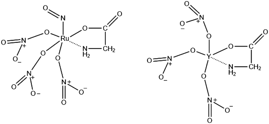
The combustion synthesis can be tuned in many ways. Firstly, one can vary the type of fuel. The combustion synthesis is a redox reaction in which the fuel is the reducing agent. Various organics have been used as fuels, including citric acid, polyvinyl alcohol (PVA), ethylenediaminetetraacetic acid (EDTA), urea, glycine, alanine, carbohydrazide, ethylene glycol or mixed variations.36 The fuel alters the mode of combustion and the properties of the products as it has a unique value for the heat of combustion (kJ g−1 or kJ mol−1)37,38 and decomposition temperature. Interestingly, it has been found that only fuels with the amino functional group can result in vigorous reactions.38–41 These functional groups complex with metal cations (Fig. 1) and decompose at low temperatures to ammonia, which undergoes a redox reaction with the nitrogen oxides (from the decomposed nitrates) resulting in water and nitrogen as products.39 An example of such a fuel is glycine. Glycine is a zwitterion that enables it to form a complex with various metal ions and prevent them from selectively precipitating.42,43 In addition, the majority of studies that use combustion to synthesize pyrochlores use glycine as fuel.21–24,27,28,33 For these reasons, glycine will be investigated primarily in this study.
 |
| | Fig. 1 An illustration of glycine as complexing agent for Ru and Y cations. | |
This relates to another important parameter that can be varied, namely the fuel-to-oxidiser ratio denoted ϕ. The oxidiser:fuel ratio is reported to have a significant impact on the structure and morphology of the products.44–46 It affects the amount of heat evolved and the effectiveness of the reaction.46 For the combustion synthesis, metal nitrates are used as precursors or other precursors (such as oxides) are treated in nitric acid to produce nitrates.22 When ϕ < 0.7, a smouldering combustion synthesis (SCS) is said to take place with a maximum temperature below 600 °C (Tm < 600 °C).38 On the other hand, when 0.7 < ϕ < 1.2 or 1.2 < ϕ < 1.6, a volume combustion synthesis (VCS, 1150 °C < Tm < 1350 °C) or self-propagating high temperature synthesis (SHS, 800 °C < Tm < 1100 °C) takes place, respectively.47 It is important for the properties of the product and health, safety and environment (HSE) reasons to know which mode of combustion will take place. Increasingly fuel rich mixtures decreases the combustion intensity, which increases both safety and yield.44 On the other hand, more violent combustion modes (fuel lean) are preferred to ensure phase-pure products, reduce particle size, prevent dopant segregation and eliminate the need for post-processing, but specialised equipment is required in this case to withstand the high temperature shock wave.40,44
Furthermore, it should be noted that combustion can take place from a solution of mixed precursors (solution combustion),30 from a dried gel (gel combustion)40,48,49 or from a dehydrated mixture of reactants (solid-state combustion).37,50 The synthesis of pyrochlores is normally undertaken by a gel combustion synthesis,21–29 although there have been some reports where solution combustion was used.30,32
Modifications to the combustion synthesis have also been made. Chen et al. added an inert soluble salt to the reactant mixture solution prior to combustion to break up the three-dimensional porous structure, inhibit agglomeration and act as an inorganic template, thus increasing the surface area.36 They named this synthesis the salt-assisted solution combustion synthesis (SSCS) and found a nine-fold increase in the specific surface area of the product after adding molten salts.36 However, if too much salt was added combustion did not occur.36 Similarly, molten salt mixtures have been used to increase the kinetics of pyrochlore formation by the increased rate of diffusion in a molten salts mixture.51 These syntheses are often collectively referred to as molten salt syntheses (MSS).
In this work, we present an alternative synthesis method to synthesise porous yttrium ruthenate pyrochlores with a glycine combustion synthesis. This new synthesis method significantly reduces the calcination time required to synthesise phase-pure yttrium ruthenate pyrochlores and provides highly porous particles with increased electrocatalytic activity. Different fuel types, ruthenium precursors and ϕ have been studied. We also show the effect of varying the ignition temperature, calcination temperature and time spent at 1000 °C. Furthermore, the use of molten salts to form pyrochlores at lower temperatures has also been investigated. The calcination temperature could not be lowered below 1000 °C. However, by using the glycine combustion reaction we significantly lowered the time required at 1000 °C. We show that a calcination time of only two hours is needed to produce highly porous yttrium ruthenate pyrochlores. In addition, we show that these pyrochlores have increased activity and stability compared to that prepared by citric acid and to state-of-the-art IrO2 and RuO2. The use of molten salts decreased the time required at 1000 °C to obtain a phase-pure pyrochlore, but affected the electrocatalytic activity negatively.
2 Experimental
2.1 Synthesis of yttrium ruthenate pyrochlores
Different parameters of the combustion synthesis were altered to obtain the best synthesis conditions for a high-performing OER electrocatalyst. In general, yttrium(III) nitrate hexahydrate (Y(NO3)3·6H2O, Thermo scientific, 99.9%) and ruthenium(III) nitrosyl nitrate solution (Ru(NO)(NO3)x(OH)y, x + y = 3, Sigma-Aldrich, 1.5% Ru) were used as metal precursors. In some cases ruthenium(III) chloride hydrate (RuCl3·xH2O, Thermo Scientific, 99.99%) was used as the metal precursor. Nitric acid (HNO3, Sigma-Aldrich, 65%) diluted to 1 M with Milli-Q water (18.2 MΩ cm) was used to alter the fuel:oxidant ratio. Glycine (C2H5NO2, Sigma-Aldrich, 99%), alanine (C3H7NO2, Thermo scientific, 99%) and citric acid (C6H8O7, Sigma-Aldrich, 99.5%) have been used as fuels. When citric acid is used as fuel, the synthesis is similar to that of the more frequently used citric acid (sol–gel) synthesis route used in previous publications.1 In the combustion synthesis, the metal nitrate precursors (oxidant) were mixed with glycine, alanine or citric acid (fuel) to result in a combustion reaction when exposed to an ignition temperature. The intensity of the combustion reaction is controlled by the ratio between the oxidants and the fuel in the reaction mixture (ϕ). We prepared Y2Ru2O7 by using a oxidiser:fuel ratio of 1 (ϕ = 1) to evaluate if a violent explosion (VCS) would lead to a phase-pure pyrochlore. We also added nitric acid in a molar ratio of 1:2 nitric acid:metals as additional oxidiser. ϕ is calculated by dividing the sum of the oxidising and reducing valencies of the oxidiser compounds by that of the fuel (eqn (1)).48| |  | (1) |
Oxygen is an oxidising element (with a positive valency of 2), nitrogen is neutral and carbon (−4), hydrogen (−1) and the cations are reducing elements (assigned negative valencies).52 According to this, the total valence of each of the precursors and fuels can be calculated as follows:
| Yttrium nitrate: (1Y × −3) + (3N × 0) + (9O × 2) = 15 |
| Ruthenium nitrosyl nitrate: (1Ru × −3) + (2.5N × 0) + (7O × 2) + (1.5H × −1) = 9.5 |
| Ruthenium chloride: (1Ru × −3) + (3Cl × −1) = 0 |
| Nitric acid: (1H × −1) + (1N × 0) + (3O × 2) = 5 |
| Glycine: (2C × −4) + (5H × −1) + (1N × 0) + (2O × 2) = −9 |
| Alanine: (3C × −4) + (7H × −1) + (1N × 0) + (2O × 2) = −15 |
| Citric acid: (6C × −4) + (8H × −1) + (7O × 2) = −18 |
For the glycine combustion synthesis, the amount of glycine we need to add to obtain ϕ = 1 can then be calculated as follows (eqn (2)):
| |  | (2) |
where
x = 3.28. The precursors were thus mixed together in the molar ratio 1
:
1
:
1
:
3.28 (yttrium nitrate
:
ruthenium nitrosyl nitrate
:
nitric acid
:
glycine). After mixing for 2 hours, the solution was placed in a water bath at 80 °C until a dried, dark brown gel was obtained. The gel was then placed in a drying oven at 60 °C for a further three hours until the gel is completely dried out and can be crushed down to a light brown powder. For a more intense combustion, the dark-brown gel can also be directly combusted. After the chosen drying step, the dried gel is placed in an alumina crucible, which is then placed inside a special container to be combusted either on a hotplate (at 200 °C) or in a muffle furnace (at 600 °C). If the sample was combusted at 600 °C in a muffle furnace, this also serves as the first annealing step as it is then kept at 600 °C for 4 hours. The second annealing step is at 1000 °C for 8 hours. The sample combusted at 200 °C has in one case been subjected to the same heating program (600 °C for 4 hours followed by 1000 °C for 8 hours) and in another case it has been annealed for only 2 hours at 1000 °C.
We also synthesised a pyrochlore with less violent combustion by adjusting ϕ to 0.3 and 1.3 by increasing or decreasing the amount of glycine added, respectively. With ϕ = 0.3, the sample burned with a controlled flame when exposed to the ignition source. When ϕ = 1.3, only smoke was observed when exposed to the ignition source. In addition, we have used alanine and citric acid as fuels with ϕ = 1. Furthermore, we looked into the effect of adding nitric acid. When nitric acid is present, the product appears visibly more voluminous (fluffy). Both samples with and without nitric acid are phase pure after calcination. Two different Ru precursors were explored without any obvious effects on the product as long as ϕ is kept the same. We have tried both ruthenium chloride and ruthenium nitrosyl nitrate as ruthenium precursors. Different calcination temperatures lower than 1000 °C were also explored, which did not provide a phase-pure pyroclore (even as high as 950). However, we managed to shorten the time spent at 1000 °C to two hours. Since a phase-pure pyrochlore was not obtained after the combustion and post-annealing was still required, we attempted to decrease the temperature and time by employing a eutectic mixture of molten salts.
A schematic representation of the synthesis route can be seen in Fig. 2.
 |
| | Fig. 2 A schematic representation of the synthesis method(s) used in this work. | |
2.2 Physical characterisation
All X-ray diffraction (XRD) spectroscopy measurements were obtained with a Bruker D8 A25 DaVinci X-ray Diffractometer (Cu-Kα). A 60 minute scan was performed at a scan rate of 0.045° per step between 2θ-angles 10 and 90°. A fixed slit of 6 mm was used. Micrographs and elemental maps were obtained by scanning electron microscopy (SEM) with energy dispersive X-ray spectroscopy (EDX) using a Zeiss Ultra 55 LE field emission scanning electron microscope. An acceleration voltage of 5 kV was used for images and 10 kV for EDX analysis. Point EDX analysis was also performed to obtain information on the composition of the samples. Raman spectroscopy was performed by a WITec alpha300 R confocal Raman microscope (532 nm) with a Zeiss EC Epiplan objective (50× magnification) and 5 mW power. 20 accumulations of 20 seconds each were used to obtain the data. WITec control software and Project Five software were used to control the instrument, confirm the calibration and process the spectra. Electronic structure and compositional (top 5–10 nm) information was obtained through X-ray photoelectron spectroscopy (XPS) with an Axis Ultra DLD instrument (Kratos Analytical, Al Kα radiation, hν = 1486.6 eV). The spectra were obtained under ultra high vacuum (UHV) and survey spectra were obtained before high-resolution spectra of the O 1s, Ru 3d, Y 3d, Sr 3d and Ca 2p regions. CasaXPS software (Casa Software, Ltd) was used for data processing and analysis.
All X-ray absorption spectroscopy (XAS) was carried out at the Swiss-Norwegian Beamlines (SNBL, BM31) at the European Synchrotron Radiation Facility (ESRF, Grenoble, France) for the Ru K-edge and the Y K-edge, in transmission mode. A Si(111) double crystal monochromator was used in this mode. Samples were prepared by homogeneously mixing with an ideal amount of boron nitride pressed into pellets. XAS spectra were collected between 21950 and 22650 eV with a time step of 200 ms. RuO2 and Ru(0) foils were employed as reference samples. The XAS energy calibration was based on the Ru(0) foil with an absorption edge of 22117 eV. The raw data were processed by Athena (IFEFFIT package) by binning, summing and normalising it, and the absorption edge was taken as the first inflection point observed in the derivative spectrum. EXAFS least-squared refinements were performed using DL-EXCURV that performs curve fitting of theoretical χth(k) to experimental χexp(k) by employing curved wave theory. We have also calculated ab inito phase shifts for the expected neighbouring elements and carried out least-squares refinements using a k3 weighting scheme. The energy shift (EF), coordination number (N), bond lengths (R) and Debeye–Waller factors were refined for two shells.
Brunauer–Emmett–Teller (BET) measurements were carried out using a Micrometrics Tristar 3000. The nitrogen adsorption–desorption isotherms at −197.80 °C were measured with TriStar II Plus 3.03 software. The samples were degassed overnight at 250° with a Degas Tristar 3000 before measurements.
2.3 Electrochemical characterisation
The electrochemical data provided in this paper were collected using a 3-electrode RDE/RRDE glass cell (Pine Research Instrumentation) with a Pt counter electrode (CE) and a reversible hydrogen electrode (RHE) reference electrode (RE). The cell contained 150 mL of 0.5 M H2SO4 (Merck, 95–97% diluted with 18.2 MΩ cm Milli-Q water) and all data were recorded with a BioLogic VMP3 potentiostat. The working electrode (WE) was a glassy carbon (GC, ø 5 mm) rotating disk electrode (Pine Research Instrumentation, AFE3T050GC) operating at 1600 rpm. 10 μL of electrocatalyst ink (2 mg of pyrochlore in a mixture of 95 μL DI water, 95 μL 2-propanol (C3H7OH, Sigma-Aldrich, 99.5%) and 10 μL Nafion 117 (C9HF17O5S, Sigma-Aldrich, 5% in a mixture of lower aliphatic alcohols and water)) was drop-casted on the GC disk surface. Consecutive tests including cyclic voltammetry (CV), linear sweep voltammetry (LSV) and potential holds/ chronoamperometry (CA) were performed on each electrocatalyst (Table 1). The LSVs were iR corrected using the ZIR function in EC-lab employing 85% of the ohmic resistance measured through electrochemical impedance spectroscopy (EIS).
Table 1 Electrochemical tests performed in chronological order
|
|
Potential (V) |
Scan rate (mV s−1) |
| 1. 5 CVs |
0.2–1.4 |
50 |
| 2. LSV |
1.1–1.6 |
5 |
| 3. 3 CVs each |
0.2–1.4 |
5, 10, 20 |
|
|
|
50, 100, 200 |
|
|
|
300, 400, 500 |
| 4. 4 min potential holds (CA) |
1.45, 1.47, 1.49 |
|
|
|
1.50, 1.51, 1.52 |
|
|
|
1.53, 1.54, 1.55 |
|
|
|
1.56 and 1.57 |
|
| 5. 100 CVs |
1.4–1.6 |
150 |
| 6. LSV |
1.1–1.6 |
5 |
| 7. 3 CVs each |
0.2–1.4 |
5, 10, 20 |
|
|
|
50, 100, 200 |
|
|
|
300, 400, 500 |
| 8. 100 CVs |
0.2–1.3 |
50 |
| 9. LSV |
1.1–1.6 |
5 |
| 10. 3 CVs each |
0.2–1.4 |
5, 10, 20 |
|
|
|
50, 100, 200 |
|
|
|
300, 400, 500 |
| 11. 700 CVs |
1.4–1.6 |
150 |
| 12. LSV |
1.1–1.6 |
5 |
| 13. 3 CVs each |
0.2–1.4 |
5, 10, 20 |
|
|
|
50, 100, 200 |
|
|
|
300, 400, 500 |
3 Results and discussion
3.1 Choice of fuel
Glycine, alanine and citric acid can be successfully employed towards the combustion synthesis. When ϕ = 1, all three fuels produce phase-pure pyrochlores as evidenced from the X-ray diffractogram in Fig. 3. When zooming in on the (222) peak (inset in Fig. 3) it can be seen that it is located at the highest 2θ value when glycine is used, followed by citric acid and then alanine. The peaks shift according to the lattice parameter (a) of the pyrochlore and therefore indicate that Y2Ru2O7 synthesised with glycine has the smallest lattice parameter and that synthesised with alanine has the largest. Furthermore, it can be seen that glycine produces a visibly more voluminous and less compact combustion product than alanine (Fig. S4, ESI†). However, both combusted in violent reactions.
 |
| | Fig. 3 X-ray diffractograms of three phase-pure Y2Ru2O7 pyrochlores prepared by three different fuel types: glycine, alanine and citric acid. The inset shows a magnification of the (222) peak. | |
In addition, it can be seen from the SEM images in Fig. 4 that both alanine and glycine produce porous particles, where glycine produces particles that appear to be the most porous of the three. When citric acid is used as fuel, the particles are visibly more compact and non-porous. The porous structures result from the more vigorous reactions of the fuels with amino functional groups that decompose to ammonia, and reacts with the decomposed nitrates producing nitrogen gas.39
 |
| | Fig. 4 SEM micrographs of three phase-pure Y2Ru2O7 pyrochlores prepared by three different fuel types: glycine, alanine and citric acid. | |
3.2 Oxidiser![[thin space (1/6-em)]](https://www.rsc.org/images/entities/h3_char_2009.gif) :fuel ratio (ϕ)
:fuel ratio (ϕ)
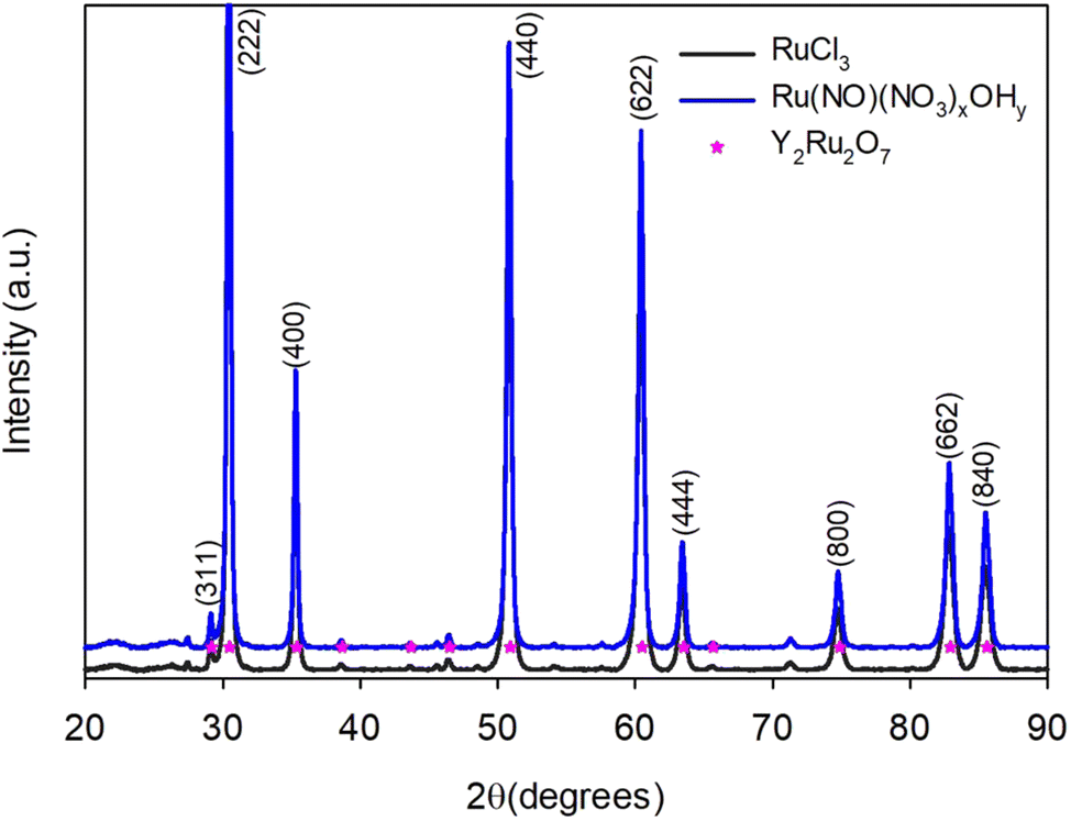
Four different oxidiser:fuel ratios (ϕ) have been investigated to evaluate the effect on the reaction intensity, intermediates and product. The values that have been evaluated are ϕ = 0.3 (SCS), 0.8 (VCS), 1 (VCS), 1.3 (SHS). After calcining at 1000 °C for 9 hours, three phase-pure pyrochlores were obtained and a RuO2 impurity phase was observed for ϕ = 0.3 (Fig. 5). In the case of ϕ = 0.8 and 1, violent explosions were observed. The product was visibly more voluminous in the case of ϕ = 1, and seemed slightly more compact when ϕ = 0.8. When ϕ = 1.3, smoke was observed and the brown powder turned grey without a violent combustion. Lastly, a flame that burned out in about 30 seconds was observed in the case of ϕ = 0.3. It is reported that a ϕ value below 0.7 will combust with the lowest temperature.38 This is evident from the fact that this is the only non-phase pure pyrochlore, likely due to a lack of heat during combustion (due to the low Tad).
 |
| | Fig. 5 X-ray diffractograms of four pyrochlores prepared by glycine combustion with ϕ = 0.3, 0.8, 1 and 1.3, calcined at 1000 °C. | |
Even though both ϕ = 0.8 and ϕ = 1 produced phase-pure pyrochores after violent reactions, differences can be observed in the X-ray diffractograms before calcining for 9 hours at 1000 °C. From Fig. 6 it can be seen that when ϕ = 0.8, only the RuO2 phase has started to form after combustion. However, when ϕ = 1, it can be seen that sufficient energy was present for the Y2O3 phase to form as well. There are no signs of the pyrochlore phase in neither cases.
 |
| | Fig. 6 X-ray diffractograms of pyrochlores prepared by glycine combustion with ϕ = 0.8 and 1. The diffractograms were collected after combustion and before any calcination procedures. | |
3.3 Ru precursor
Both ruthenium chloride and ruthenium nitrosyl nitrate were used as precursors in this study. Ruthenium chloride is normally used in the established citric acid route, whereas nitrate precursors are required for typical combustion reactions to also serve as oxidants. Therefore, we used both to see if the Ru precursor has an effect on the product. The gel intermediate is darker brown in color and less voluminous when chloride is used as a precursor compared to nitrate (Fig. S3, ESI†). However, no changes are observed in the diffractograms and both precursors yield phase-pure pyrochlores (Fig. 7).
 |
| | Fig. 7 X-ray diffractograms of pyrochlores prepared with ruthenium chloride and ruthenium nitrosyl nitrate as precursors. | |
3.4 Combustion/calcination procedures
Before exposing the gel to an ignition source, it is usually dried. However, it should be noted that this is not a necessity and wet gels can also be used as combustion precursors. The darker, wet gel leads to a more intense reaction than the dried gel (Fig. S5, ESI†). Both gel-types lead to phase-pure pyrochlores after calcination and there are no visible changes in the diffractograms (Fig. 9).
After the gel has been combusted, post-treatment is necessary to obtain the pyrochlore. We investigated whether the combustion reaction could decrease the required temperature below 1000 °C to obtain a phase-pure pyrochlore. Fig. 8 shows the diffractograms after the combusted intermediates have been exposed to three different temperatures. After 6 hours at 600 °C, no pyrochlore has formed and a mixture of Y2O3 and RuO2 is present. After 9 hours at 950 °C, the pyrochlore phase has formed, but a RuO2 impurity phase is present. However, after only 6 hours at 1000 °C, a phase-pure pyrochlore formed.
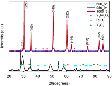 |
| | Fig. 8 X-ray diffractogram of yttrium ruthenate after glycine combustion and calcination at 600 °C, 950 °C and 1000 °C. | |
We found that the lowest amount of time required at 1000 °C to form a phase-pure pyrochlore is two hours. When synthesising these pyroclores with the established citric acid/sol–gel routes, nine hours is normally the lowest time reported spent at 1000 °C to form a phase-pure pyrochlore.29,32 Therefore, we also used this as our upper limit. All samples that have been exposed to this form phase-pure pyrochlores, regardless of the combustion temperature or phase of the gel. Furthermore, Fig. 9 shows that the pyrochlore phase can be obtained after a combustion at 200 °C by exposing the combusted product to 1000 °C for as little as one hour. However, the samples calcined for one or two hours both contain a RuO2 impurity phase.
 |
| | Fig. 9 X-ray diffractograms of pyrchlores prepared by the glycine combustion synthesis and calcined at 1000 °C for different amounts of time. | |
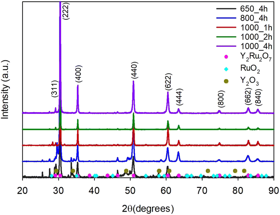
In a mixture of molten salts, as a modified combustion with added molten salt synthesis (MSS), we attempted lower calcination temperatures (650 °C and 1000 °C) and different times at 1000 °C (1, 2 and 4 hours). These results can be seen in Fig. 10. Interestingly, if we compare the sample calcined at 600 °C for 6 hours without MSS (Fig. 8) and the sample with MSS at 600 °C for 4 hours, it is clear that the molten salt mixture indeed facilitates the formation of the pyrochlore phase. Without MSS, a combination of the two oxide phases (RuO2 and Y2O3) is present, but no pyrochlore phase (Fig. 8). With MSS, a pyrochlore phase is present along with the oxides (Fig. 10). At 800 °C in the molten salt mixture, a pyrochlore phase has clearly formed, but both RuO2 and Y2O3 impurity phases are still present. After just one hour at 1000 °C in the molten salt mixture, a pyrochlore is formed with only a minor RuO2 impurity phase, and after 2 and 4 hours at 1000 °C a phase-pure pyrochlore is present (Fig. 10).
 |
| | Fig. 10 X-ray diffractograms of Y2Ru2O7 samples prepared by the combustion synthesis followed by calcining in a molten salt mixture at different temperatures and times. | |
In Fig. 11, SEM images of the products before and after calcination can be seen. It is clear that porous particles are formed after combustion, and that this porous structure is maintained after calcining for two- and nine hours at 1000 °C. When the combusted oxides are mixed with molten salts and calcined at 1000 °C for two hours, larger pyrochlore crystallites form within the porous matrix. The larger particles form due to the increased kinetics provided by the molten salts.51 The Brunauer–Emmett–Teller (BET) surface area of the particles prepared by glycine combustion is 18.5 m2 g−1, and that of the samples prepared with an MSS step is ten times lower (Fig. S24 and S25, ESI†). This shows the important effects of post-processing on particle properties. The surface are of the glycine combustion produced particles is of the highest reported for these types of particles to date. A defect-rich yttrium ruthenate pyrochlore prepared by quenching had a BET surface area of 15.6 m2 g−1,5 and one prepared by polymer entrapment flash pyrolysis was reported to have a surface area of 14.8 m2 g−1.4 The surface area of yttrium ruthenate pyrochlores prepared by conventional sol–gel/citric acid approaches range from around 4 m2 g−112,52 to 7–8 m2 g−1.1,53 This clearly shows that the glycine combustion method provides increased BET surface areas compared to these often-used methods.
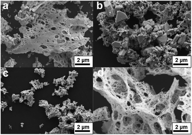 |
| | Fig. 11 SEM micrographs of pyrochlores prepared by glycine combustion (a) before calcination, (b) after 2 hours calcination in molten salts, (c) after 2 hours of calcination at 1000 °C and (d) after 9 hours calcination at 1000 °C. | |
XPS analysis was also performed on three of the samples to obtain additional information on the effects of the synthesis method on surface – and electronic structure. Fig. 12 portrays the Ru 3d XPS spectra of the samples prepared with citric acid and glycine (both calcined at 1000 °C for 9 hours) and that of the sample calcined in molten salts for 2 hours at 1000 °C. The Ru 3d spectra were fitted using two sets of doublets, a peak corresponding to C 1s (with a constant position at 284.8 eV) and two satellite peaks. The doublets consist of one peak corresponding to Ru 3d5/2 and the other to Ru 3d3/2, for which a fixed area ratio of 3/2 was used, as well as a constant peak separation of 4.15 eV.1,54 The fact that there are two sets of doublets indicates that there are two Ru oxidation states present. One doublet has peaks at 281.6 eV (3d5/2) and 285.8 eV (3d3/2), and can be ascribed to Ru4+.1 The other has a 3d5/2 peak at 282.4 eV and a 3d3/2 peak at 286.5 eV and can likely be ascribed to Ru5+, or another higher oxidation state (Rux+).54,55 The ratio of the near-surface concentration of the two oxidation states can be determined by the ratio of the 3d5/2 peaks (Fig. 12). The pyrochlore prepared by the combustion MSS has the highest concentration of Ru4+, followed by the sample prepared by citric acid and then the sample prepared by the glycine combustion synthesis (9 hours calcination). This shows that the sample prepared by the glycine combustion is the most oxidised in the surface region. Clearly, the synthesis method affects the oxidation state of the active Ru species.
 |
| | Fig. 12 Ru 3d XPS spectra of pyrochlores prepared by citric acid, glycine combustion and glycine combustion with a molten salt mixture as the calcination procedure. | |
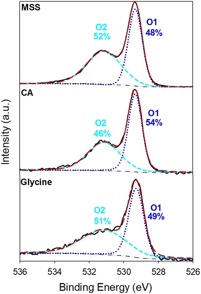
The O 1s XPS spectra (Fig. 13) also contains valuable information. In this case, the spectra show that the MSS sample contains the highest concentration (52%) of an oxygen species (at 531 eV and labeled O2) commonly associated with defective oxygen.5 The other peak at 529.3 eV is associated with lattice oxygen.5 The O 1s spectra follow the same trend as the oxidation state of Ru. MSS provides the most defective oxygen in the surface region, followed by the sample prepared with glycine and then citric acid. This shows a possible correlation between an increased Ru oxidation state and defective oxygen. Both of these factors are charge compensating mechanisms that maintain charge neutrality when an oxide is acceptor doped. This can be the case as more Y occupies the Ru site.
 |
| | Fig. 13 XPS O 1s spectra of pyrochlores prepared by citric acid, glycine combustion and glycine combustion with a molten salt mixture as the calcination procedure. | |
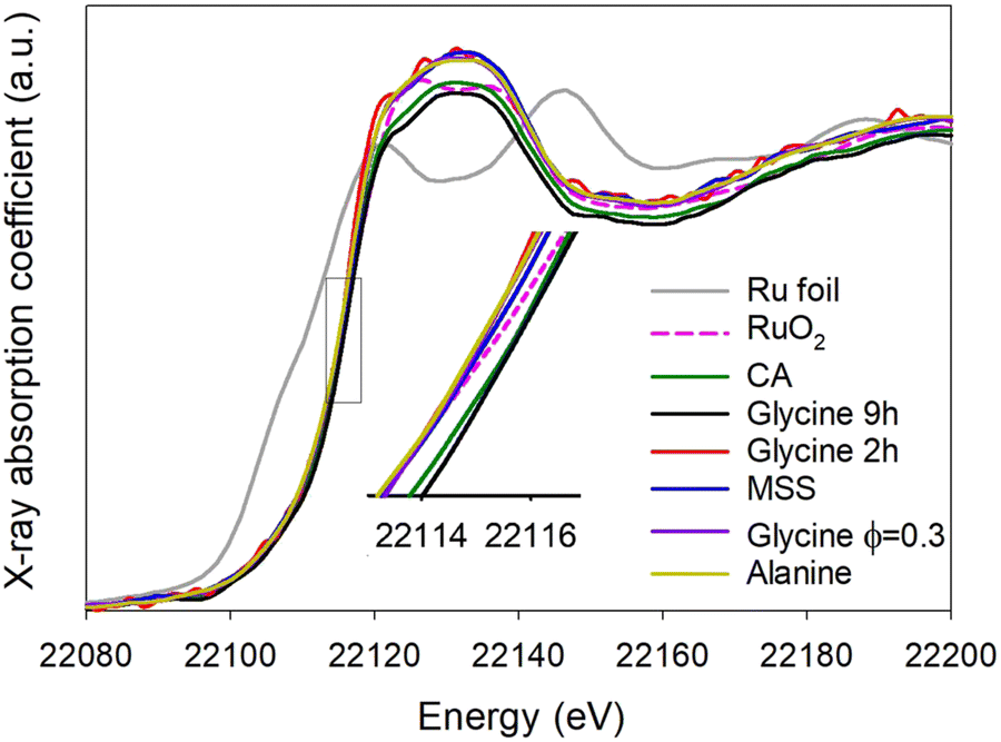
The XANES spectra can be seen in Fig. 14 and show that the synthesised pyrochlores have a similar oxidation state to RuO2 as evidenced by similar positions of the Ru K-edge. The absorption energy (E0) was inferred from the first inflection point in the second derivative spectra and related directly to the oxidation state.1 The absorption energy for Ru metal (Ru0) was found to be 22112.91 eV and that of RuO2 (Ru4+) 22116.11 eV. For the pyrochlores E0 varies between 22115.6 eV for the glycine 2 h sample and 22116.4 eV for the glycine 9 h sample. All of the pyrochlores have an oxidation state close to 4+, in agreement with reported values for similar materials in literature.56
 |
| | Fig. 14 Ruthenium K-edge XANES spectra of pyrochlores prepared by varying synthesis conditions. | |
Fig. 15 shows the Y K-edge and proves that Y in all synthesised pyrochlores has an oxidation state similar to that of Y2O3, i.e. +3. Fig. 16 shows the phase-corrected extended X-ray absorption fine structure (EXAFS) Fourier transforms of the Ru K-edge of the pyrochlores. The local coordination environments can be inferred from these results and it can be seen that the first coordination sphere is fitted by a Ru–O scattering path at ca. 1.99 Å and that of the second sphere is fitted by Ru–Ru and Ru–Y at ca. 3.6 Å. The exact values for the Ru–O and Ru–Ru/Y spheres of each of the samples can be inferred from Tables S1 and S2 (ESI†), respectively. Fig. S17 (ESI†) shows the EXAFS data without any processing in Excurv.
 |
| | Fig. 15 Yttrium K-edge XANES spectra of pyrochlores prepared by varying synthesis conditions. | |
 |
| | Fig. 16 Experimental and least squares refined of k3χ(k) (left) and EXAFS Fourier transforms (right) for pyrochlores obtained by altering different synthesis parameters. | |
3.5 Electrochemical performance
The double layer (DL) capacitance of the samples was obtained by varying the scan rate of CVs in a non-faradaic region and plotting the current at 1.2 V versus the scan rate (Fig. S6, ESI†). This capacitance is directly proportional to the electrochemically active surface area (ECSA) of the electrocatalysts. ECSA is obtained by dividing the capacitance value by a specific capacitance of 0.35 mF cm−2 reported for oxides.57 The pyrochlores have similar ECSAs, except for the one prepared by MSS which has one order of magnitude lower DL capacitance than the other samples. This is because it was difficult to obtain a homogeneous electrocatalyst ink for the MSS sample, leading to a poor catalyst layer on the surface of the GC. Furthermore, it can be seen that lowering the time spent at 1000 °C was advantageous for a higher ECSA since the sample calcined for only 2 hours has the highest ECSA.
Fig. 17 shows the 5th voltammogram of each sample before any other testing. Four oxidation features and four reduction features can be observed for the pyrochlores, where the first feature is obscured for the sample when ϕ = 0.3. Since the surface area of the MSS sample is so low, no discernible features can be seen for this sample. It is not clear exactly which redox transitions can be ascribed to these features since contradicting information is available in the literature. However, the first peak centered around 0.35 V can likely be ascribed to the Ru2+/Ru3+ transition,9 the second at 0.5 V to Ru3+/Ru4+,9,58,59 and the last two features at 0.9 and 1.1 V to Ru4+/Ru5+9,59 or Ru4+/Ru6+,58 and Ru6+/Ru8+,58 respectively. After being tested at higher potentials (LSV, CA and 100 stability cycles), CVs were recorded between 0.2 and 1.3 V, with the main goal of cycling the electrode in a lower potential range for regenerative purposes. In Fig. S7 (ESI†), it can be seen that there are now barely three visible oxidation features. One feature and a shoulder can be seen between 0.3 and 0.7 V, and another feature centered at 1.1 V. Two reduction features are visible at the same positions. This indicates that the active surface of the pyrochlore electrocatalysts changes during electrochemical testing.
 |
| | Fig. 17 The fifth cyclic voltammogram recorded on each pyrochlore sample at 50 mV s−1 in 0.5 M H2SO4. | |
It can be seen that all three pyrochlores prepared by the glycine combustion synthesis (regardless of calcination temperature or ϕ) have a superior activity than the pyrochlore prepared by citric acid (Fig. 18). The mass activity improvement over RuO2 and IrO2 is also illustrated in the ESI† (Fig. S9). All pyrochlore samples perform better than the benchmark RuO2 and IrO2. In addition, the glycine combustion sample calcined for two hours perform slightly worse at 1.6 V than those calcined for 9 hours (Fig. 18). The decreased performance could be due to the RuO2 impurity phase observed in Fig. 9. This impurity phase is also observed where ϕ = 0.3. Since RuO2 clearly performs worse than the pyrochlores (Fig. 18 and Fig. S8, S9, ESI†), this phase will not lead to any increase in activity of the pyrochlores reported, illustrating that even with small impurity phases the pyrochlores still show enhanced activity. The logarithmic plots of current versus potential (obtained from CA measurements) with straight line portions corresponding to the Tafel region can be seen in Fig. 19. The plots for the benchmark RuO2 and IrO2 are also included for comparison. All pyrochlore samples (except MSS) have similar Tafel slopes (42–44 mV dec−1), that are just slightly higher than that of IrO2 (38 mV). The Tafel slopes of the pyrochlores are considerably lower than that of RuO2 (66 mV). The values reported here are among the lowest reported for these types of pyrochlores that have been reported previously in literature,1,60 and correspond well to the Tafel slopes reported for other porous pyrochlores. Kim et al. reported a Tafel slope of 37 mV dec−1 for a porous Y2[Ru1.6Y0.4]O7−d pyrochlore synthesised by a combustion-type synthesis.56 It should be noted that only a limited region of the polarization curves could be fitted to a straight line to obtain the Tafel slope, and that this is likely only one of two Tafel slopes that can be fitted within this curve.61 An alternative is to fit the entire polarization curve as described by Reksten et al.62 These fits and the results can be observed in in the ESI† (Fig. S11).
 |
| | Fig. 18 LSVs (active area normalised) recorded at 5 mV s−1 in 0.5 M H2SO4 of Y2Ru2O7 synthesised under different conditions. The LSVs for reference RuO2 and IrO2 are also included. | |
 |
| | Fig. 19 Logarithmic plots of the current density obtained from potential steps (CA) in H2SO4 of Y2Ru2O7 synthesised under different conditions. The plots for reference RuO2 and IrO2 are also included. The straight line portions used to obtain the Tafel slopes are indicated. | |
To evaluate the effect of potential cycling on the pyrochlores, we used 100 CVs between 1.4 and 1.6 V, followed by 100 cycles between 0.2 and 1.3 V (down-cycling), and concluded with 700 additional cycles between 1.4 and 1.6 V (Fig. S13, ESI†). After each set of cycles, an LSV was performed to evaluate how the activity changed (Fig. S12, ESI†). In addition, CVs in the non-faradaic region were performed to evaluate the change in the double layer capacitance/ECSA with cycling (Fig. 20). All pyrochlores as well as the reference samples show a decrease in activity after the first 100 cycles (an LSV and CA experiment has also been performed between the first LSV and 100 CVs, see Table 1). The activity then increases again for all samples after down cycling, confirming the use of cycling in a lower potential range as a re-activation procedure. After an additional 700 cycles, the reference samples (RuO2 and IrO2), the glycine ϕ = 0.3 sample and the citric acid (labelled CA) sample undergo a further decrease in activity. However, the activity remains constant or changes very little for the other samples prepared by glycine combustion (Fig. S12, ESI†).
 |
| | Fig. 20 A bar chart illustrating the change in electrochemical active surface area (ECSA) for the pyrochlores prepared by different synthesis methods during the electrochemical test protocol. Gly and CA refer to glycine and citric acid, respectively. | |
The citric acid pyrochlore and RuO2 both exhibit a decrease in ECSA upon consecutive cycling. IrO2 exhibits an increased ECSA after down cycling, but exhibits a constant ECSA for the rest of the testing procedure. On the other hand, the two pyrochlores prepared by glycine combustion (ϕ = 1), exhibit increased ECSA with testing. For the sample calcined for 9 hours, the increase occurred after 100 CVs and it then maintained the same ECSA after that. For the sample calcined for 2 hours, the increase occurred after down cycling and was sustained after 700 cycles. The glycine ϕ = 0.3 sample exhibits no change in ECSA throughout cycling, whereas the MSS sample exhibits a slight decrease after 100 CVs, and then maintains the same. It is possible that each pyrochlore prepared by a different synthesis technique undergoes unique structural changes during cycling and down-cycling. This can be due to the effect of the synthesis method on defect composition and overall structure.5
4 Conclusions
In this study we establish a glycine combustion synthesis method that can be effectively used to produce phase pure Y2[Ru2−xYx]O7. The synthesized pyrochlores show improved electrochemical activity and stability for the oxygen evolution reaction compared to established methods using the citric acid sol–gel synthesis. We show that employing this method reduces the time required at 1000 °C down to 2 hours in order to obtain the phase pure pyrochlore structure. By mapping the synthesis parameter space we identified the optimum parameters needed to produce porous pyrochlores in a faster, more efficient manner. In addition, we found that the combustion synthesis is flexible and the mode of combustion can be altered if required.
Data availability
The authors of this manuscript hereby declare that the data is available in the ESI.†
Conflicts of interest
There are no conflicts to declare.
Acknowledgements
This work was supported by the Research Council of Norway, project number 325873. The authors thank Dr. Henrik Erring Hansen, Prof. Karina Mathisen and Dr. Dragos Stoian for their help and support with XAS measurements and data analysis. We acknowledge the Swiss Norwegian beamlines (SNBL at ESRF) for XAS facilities. The BM31 setup was funded by the Swiss National Science Foundation (grant 206021_189629) and the Research Council of Norway (grant 296087). The authors would also like to acknowledge and thank Dr. Øystein Dahl at SINTEF for performing the XPS measurements.
References
- J. Kim,
et al., High-performance pyrochlore-type yttrium ruthenate electrocatalyst for oxygen evolution reaction in acidic media, J. Am. Chem. Soc., 2017, 139, 12076–12083 CrossRef CAS PubMed.
- H. Horowitz, J. Longo and H. Horowitz, Oxygen electrocatalysis on some oxide pyrochlores, J. Electrochem. Soc., 1983, 130, 1851 CrossRef CAS.
-
H. Horowitz, J. Longo, H. Horowitz and J. Lewandowski, The synthesis and electrocatalytic properties of nonstoichiometric ruthenate pyrochlores, Solid State Chemistry in Catalysis, ACS Publications, 1985 Search PubMed.
- P.-C. Shih, C. Zhang, H. Raheja, C.-J. Sun and H. Yang, Polymer Entrapment Flash Pyrolysis for the Preparation of Nanoscale Iridium-Free Oxygen Evolution Electrocatalysts, ChemNanoMat, 2020, 6, 930–936 CrossRef CAS.
- T. Liu,
et al., Quenching as a Route to Defect-Rich Ru–Pyrochlore Electrocatalysts toward the Oxygen Evolution Reaction, Small Methods, 2022, 6, 2101156 CrossRef CAS PubMed.
- D. A. Kuznetsov,
et al., Tailoring lattice oxygen binding in ruthenium pyrochlores to enhance oxygen evolution activity, J. Am. Chem. Soc., 2020, 142, 7883–7888 CrossRef CAS PubMed.
- M. A. Hubert,
et al., Acidic oxygen evolution reaction activity–stability relationships in Ru-based pyrochlores, ACS Catal., 2020, 10, 12182–12196 CrossRef CAS.
- J. Parrondo, M. George, C. Capuano, K. E. Ayers and V. Ramani, Pyrochlore electrocatalysts for efficient alkaline water electrolysis, J. Mater. Chem. A, 2015, 3, 10819–10828 RSC.
- J. B. Goodenough, R. Manoharan and M. Paranthaman, Surface protonation and electrochemical activity of oxides in aqueous solution, J. Am. Chem. Soc., 1990, 112, 2076–2082 CrossRef CAS.
- D. F. Abbott,
et al., Design and synthesis of Ir/Ru pyrochlore catalysts for the oxygen evolution reaction based on their bulk thermodynamic properties, ACS Appl. Mater. Interfaces, 2019, 11, 37748–37760 CrossRef CAS PubMed.
- C. Abate, K. Duncan, V. Esposito, E. Traversa and E. D. Wachsman, Synthesis and Characterization of Y2Ru2O7 and Y2−xPrxRu2O7 for Cathode Application in Intermediate Temperature Solid Oxide Fuel Cells, ECS Trans., 2006, 1, 255 CrossRef CAS.
- J. Park, M. Park, G. Nam, M. G. Kim and J. Cho, Unveiling the catalytic origin of nanocrystalline yttrium ruthenate pyrochlore as a bifunctional electrocatalyst for Zn–air batteries, Nano Lett., 2017, 17, 3974–3981 CrossRef CAS PubMed.
- K. Sardar,
et al., Bismuth iridium oxide oxygen evolution catalyst from hydrothermal synthesis, Chem. Mater., 2012, 24, 4192–4200 CrossRef CAS.
- K. Sardar,
et al., Water-splitting electrocatalysis in acid conditions using ruthenate–iridate pyrochlores, Angew. Chem., 2014, 126, 11140–11144 Search PubMed.
- W. Sun,
et al., OER activity manipulated by IrO6 coordination geometry: an insight from pyrochlore iridates, Sci. Rep., 2016, 6, 38429 CrossRef CAS PubMed.
- D. L. Burnett,
et al., Exploiting the flexibility of the pyrochlore composition for acid-resilient iridium oxide electrocatalysts in proton exchange membranes, J. Mater. Chem. A, 2021, 9, 25114–25127 RSC.
- E. Carlos, R. Martins, E. Fortunato and R. Branquinho, Solution combustion synthesis: towards a sustainable approach for metal oxides, Chem. – Eur. J., 2020, 26, 9099–9125 Search PubMed.
- A. Varma, A. S. Mukasyan, A. S. Rogachev and K. V. Manukyan, Solution combustion synthesis of nanoscale materials, Chem. Rev., 2016, 116, 14493–14586 CrossRef CAS PubMed.
- M. K. Alam, M. S. Hossain, M. Kawsar, N. M. Bahadur and S. Ahmed, Synthesis of nano-hydroxyapatite using emulsion, pyrolysis, combustion, and sonochemical methods and biogenic sources: a review, RSC Adv., 2024, 14, 3548–3559 RSC.
- M. M. Francis,
et al., Soft sol–gel combustion synthesis: a potential route for functional nanocomposites of copper-based mixed valent oxides and cermet, Chem. Eng. J., 2024, 494, 152735 CrossRef.
- Y. Zhang,
et al., Preparation and characterization of pyrochlore oxide Y2Ti2O7 nanocrystals via gel-combustion route, Ceram. Int., 2014, 40, 5223–5230 CrossRef CAS.
- Z. Wang,
et al., Two-Phase LaLuZr2O7 Transparent Ceramic with High Transparency, J. Am. Ceram. Soc., 2014, 97, 2035–2037 CrossRef CAS.
- X. Zou, G. Zhou, H. Yi, G. Zhang and S. Wang, Fabrication of transparent Y2Zr2O7 ceramics from combustion-synthesized powders, J. Am. Ceram. Soc., 2011, 94, 1002–1004 CrossRef CAS.
- N. Orlovskaya,
et al., Glycine–nitrate synthesis of Sr doped La2Zr2O7 pyrochlore powder, Adv. Appl. Ceram., 2011, 110, 54–57 Search PubMed.
- A. Zhang, M. Lu, G. Zhou, S. Wang and Y. Zhou, Combustion synthesis and photoluminescence of Eu3+, Dy3+-doped La2Zr2O7 nanocrystals, J. Phys. Chem. Solids, 2006, 67, 2430–2434 CrossRef CAS.
- T. Feng, D. R. Clarke, D. Jiang, J. Xia and J. Shi, Neodymium zirconate (Nd2Zr2O7) transparent ceramics as a solid state laser material, Appl. Phys. Lett., 2011, 98(15), 151105 Search PubMed.
- Z. Wang,
et al., Fabrication of LaGdZr2O7 transparent ceramic, J. Eur. Ceram. Soc., 2013, 33, 643–646 CrossRef.
- Y. Ji, D. Jiang, T. Fen and J. Shi, Fabrication of transparent La2Hf2O7 ceramics from combustion synthesized powders, Mater. Res. Bull., 2005, 40, 553–559 CrossRef CAS.
- B. P. Mandal, A. Dutta, S. K. Deshpande, R. N. Basu and A. K. Tyagi, Nanocrystalline Nd2−yGdyZr2O7 pyrochlore: facile synthesis and electrical characterization, J. Mater. Res., 2009, 24, 2855–2862 CrossRef CAS.
- N. ArulaDhas,
et al., Combustion synthesis and properties of fine-particle rare-earth-metal zirconates, Ln2Zr2O7, J. Mater. Chem., 1993, 3, 1289–1294 RSC.
- K. Zhang, G. Wen, H. Zhang and Y. Teng, Self-propagating hightemperature synthesis of Y2Ti2O7 pyrochlore and its aqueous durability, J. Nucl. Mater., 2015, 465, 1–5 CrossRef CAS.
- B. Matovic,
et al., Synthesis and characterization of pyrochlore lanthanide (Pr, Sm) zirconate ceramics, J. Eur. Ceram. Soc., 2020, 40, 2652–2657 Search PubMed.
- Z. Wang,
et al., Transparent La2−xGdxZr2O7 ceramics obtained by combustion method and vacuum sintering, J. Alloys Compd., 2014, 585, 497–502 CrossRef CAS.
- Q. Zhang,
et al., Lead-Induced Microstrain in Synthesis and Manipulation of Porous Pyrochlore for Boosting Oxygen Evolution Reaction, Adv. Funct. Mater., 2024, 34, 2306176 CrossRef CAS.
-
T. Jeyasingh, S. Saji, V. Kavitha and P. Wariar, Frequency dependent dielectric properties of combustion synthesized Dy2Ti2O7 pyrochlore oxide in AIP Conference Proceedings 1953, 2018.
- W. Chen, F. Li, J. Yu and L. Liu, A facile and novel route to high surface area ceria-based nanopowders by salt-assisted solution combustion synthesis, Mater. Sci. Eng., B, 2006, 133, 151–156 CrossRef CAS.
- C.-C. Hwang, T.-Y. Wu, J. Wan and J.-S. Tsai, Development of a novel combustion synthesis method for synthesizing of ceramic oxide powders, Mater. Sci. Eng., B, 2004, 111, 49–56 CrossRef.
- P. Erri, P. Pranda and A. Varma, Oxidizer-fuel interactions in aqueous combustion synthesis. 1. Iron(III) nitrate-model fuels, Ind. Eng. Chem. Res., 2004, 43, 3092–3096 CrossRef CAS.
- F. Li, K. Hu, J. Li, D. Zhang and G. Chen, Combustion synthesis of? – lithium aluminate by using various fuels, J. Nucl. Mater., 2002, 300, 82–88 Search PubMed.
- L. Chauhan, A. Shukla and K. Sreenivas, Properties of NiFe2O4 ceramics from powders obtained by auto-combustion synthesis with different fuels, Ceram. Int., 2016, 42, 12136–12147 CrossRef CAS.
- G. Mahmoudzadeh, S. Khorrami, S. Madani and M. Frounchi, Influence of different fuel additives at different molar ratios on the crystallite phase formation process, structural characteristics and morphology of dispersed zinc ferrite powders by sol-gel auto combustion, J. Ceram. Process. Res., 2012, 13, 368–372 Search PubMed.
- T. Peng, X. Liu, K. Dai, J. Xiao and H. Song, Effect of acidity on the glycine–nitrate combustion synthesis of nanocrystalline alumina powder, Mater. Res. Bull., 2006, 41, 1638–1645 CrossRef CAS.
- I. Kaus, P. I. Dahl, J. Mastin, T. Grande and M.-A. Einarsrud,
et al., Synthesis and characterization of nanocrystalline YSZ powder by smoldering combustion synthesis, J. Nanomater., 2006, 2006, 049283 CrossRef.
- F. Deganello, G. Marci and G. Deganello, Citrate–nitrate autocombustion synthesis of perovskite-type nanopowders: a systematic approach, J. Eur. Ceram. Soc., 2009, 29, 439–450 CrossRef CAS.
- M. Marinsek, K. Zupan and J. Maeek, Ni–YSZ cermet anodes prepared by citrate/nitrate combustion synthesis, J. Power Sources, 2002, 106, 178–188 Search PubMed.
- B. N. Sherikar, B. Sahoo and A. M. Umarji, Effect of fuel and fuel to oxidizer ratio in solution combustion synthesis of nanoceramic powders: MgO, CaO and ZnO, Solid State Sci., 2020, 109, 106426 CrossRef CAS.
- A. S. Mukasyan, C. Costello, K. P. Sherlock, D. Lafarga and A. Varma, Perovskite membranes by aqueous combustion synthesis: synthesis and properties, Sep. Purif. Technol., 2001, 25, 117–126 CrossRef CAS.
- S. H. Vajargah, H. M. Hosseini and Z. Nemati, Preparation and characterization of yttrium iron garnet (YIG) nanocrystalline powders by autocombustion of nitrate-citrate gel, J. Alloys Compd., 2007, 430, 339–343 Search PubMed.
- T. Prabhakaran and J. Hemalatha, Chemical control on the size and properties of nano NiFe2O4 synthesized by sol–gel autocombustion method, Ceram. Int., 2014, 40, 3315–3324 Search PubMed.
- C.-C. Hwang, J.-S. Tsai, T.-H. Huang, C.-H. Peng and S.-Y. Chen, Combustion synthesis of Ni–Zn ferrite powder—influence of oxygen balance value, J. Solid State Chem., 2005, 178, 382–389 CrossRef CAS.
- M. Pokhrel, S. K. Gupta, K. Wahid and Y. Mao, Pyrochlore rare-earth hafnate RE2Hf2O7 (RE = La and Pr) nanoparticles stabilized by moltensalt synthesis at low temperature, Inorg. Chem., 2019, 58, 1241–1251 CrossRef CAS PubMed.
- Q. Feng,
et al., Highly active and stable ruthenate pyrochlore for enhanced oxygen evolution reaction in acidic medium electrolysis, Appl. Catal., B, 2019, 244, 494–501 CrossRef CAS.
- Q. Feng, Z. Zhao, X.-Z. Yuan, H. Li and H. Wang, Oxygen vacancy engineering of yttrium ruthenate pyrochlores as an efficient oxygen catalyst for both proton exchange membrane water electrolyzers and rechargeable zinc–air batteries, Appl. Catal., B, 2020, 260, 118176 CrossRef CAS.
- J. Balcerzak, W. Redzynia and J. Tyczkowski, In situ XPS analysis of oxidized and reduced plasma deposited ruthenium-based thin catalytic films, Appl. Surf. Sci., 2017, 426, 852–855 CrossRef CAS.
- L. Jozwiak, J. Balcerzak and J. Tyczkowski, Plasma-deposited Ru-based thin films for photoelectrochemical water splitting, Catalysts, 2020, 10, 278 CrossRef CAS.
- J. Kim,
et al., A porous pyrochlore Y2[Ru1.6Y0.4]O7−d electrocatalyst for enhanced performance towards the oxygen evolution reaction in acidic media, Angew. Chem., Int. Ed., 2018, 130, 14073–14077 CrossRef.
- C. C. McCrory, S. Jung, J. C. Peters and T. F. Jaramillo, Benchmarking heterogeneous electrocatalysts for the oxygen evolution reaction, J. Am. Chem. Soc., 2013, 135, 16977–16987 Search PubMed.
- H. Guo, Z. Zhang and F. Wang, Role of A-sites in pyrochlore lanthanide ruthenate for electrocatalysis of oxygen evolution reaction, J. Materiomics, 2024, 10(6), 1234–1242 CrossRef.
- G. Gokagac and B. J. Kennedy, Oxidative stability of bismuth-ruthenium pyrochlore Bi2Ru2O7−y, J. Electroanal. Chem., 1994, 368, 235–239 CrossRef.
- N. Zhang,
et al., Metal substitution steering electron correlations in pyrochlore ruthenates for efficient acidic water oxidation, ACS Nano, 2021, 15, 8537–8548 CrossRef CAS PubMed.
- T. Shinagawa, A. T. Garcia-Esparza and K. Takanabe, Insight on Tafel slopes from a microkinetic analysis of aqueous electrocatalysis for energy conversion, Sci. Rep., 2015, 5, 13801 CrossRef PubMed.
- A. H. Reksten, H. Thuv, F. Seland and S. Sunde, The oxygen evolution reaction mechanism at IrxRu1−xO2 powders produced by hydrolysis synthesis, J. Electroanal. Chem., 2018, 819, 547–561 CrossRef CAS.
|
| This journal is © The Royal Society of Chemistry 2025 |
Click here to see how this site uses Cookies. View our privacy policy here. 
 Open Access Article
 This Open Access Article is licensed under a
  *,
Elise Fosdal
Closs
,
Svein
Sunde
*,
Elise Fosdal
Closs
,
Svein
Sunde