
 Open Access Article
 This Open Access Article is licensed under a Creative Commons Attribution-Non Commercial 3.0 Unported Licence
Void engineering to promote the self-cleaning properties of bactericidal zinc oxide nanopillar array coatings†
Amir
Hassanpour
 *a,
Marie-Christine
Groleau
b,
Dalya
Messaoudi
a,
Andrea A.
Greschner
a,
Katharina
Kohlmann
a,
Andreas
Ruediger
a,
Eric
Déziel
b,
Shuhui
Sun
a and
Marc A.
Gauthier
*a
*a,
Marie-Christine
Groleau
b,
Dalya
Messaoudi
a,
Andrea A.
Greschner
a,
Katharina
Kohlmann
a,
Andreas
Ruediger
a,
Eric
Déziel
b,
Shuhui
Sun
a and
Marc A.
Gauthier
*a
aInstitut National de la Recherche Scientifique, Centre Énergie Matériaux Télécommunications, Varennes, QC J3X 1P7, Canada. E-mail: amir.hassanpour@inrs.ca; marc.andre.gauthier@inrs.ca
bInstitut National de la Recherche Scientifique (INRS), Centre Armand-Frappier Santé Biotechnologie, Laval, QC H7V 1B7, Canada
First published on 3rd June 2025
Abstract
Bacterial infections are easily spread by touch, and some bacteria can survive for months on certain surfaces. Current disinfection approaches and self-sanitizing coatings have limitations, which provides the impetus for developing new inexpensive coatings that combine bactericidal activity and self-cleaning properties. One way to achieve this is to mimic natural arrays of nano-pillars, such as those found on insect wings and plant leaves. Accordingly, arrays of zinc oxide nano-pillars display self-sanitizing properties, which are influenced by their dimensions, shape, and spacing. However, a key characteristic of these coatings is their water wettability, which increases the tendency for water-borne contaminants to attach. This wettability is caused by the voids between the nano-pillars that form a network of capillaries. To address this issue, this study introduces modifications to the current hydrothermal production method to adjust the characteristics of these voids, without altering the nano-pillar density in the array. A new hierarchical ‘nano-porcupine’ morphology is also reported. These modifications to the void structure significantly affected the surface chemistry and wettability of the coatings, improving their self-cleaning properties without compromising their bactericidal activity, as demonstrated by five different tests.
1. Introduction
In 2019, bacterial antimicrobial resistance was associated with ∼5 M deaths worldwide and recent estimations suggest that this is an issue on the scale of major diseases, such as HIV and malaria.1 Moreover, it is estimated that ∼10 M people could die annually from bacterial infections in high-income countries by 2050 without a sustained effort to stem resistance.2 Controlling antibiotic-resistant bacteria in hospitals is another major challenge,3 as healthcare-associated infections are a common cause of mortality or extended hospitalization for patients who stay in highly restricted areas like intensive care units.4 For instance, certain types of bacteria spread from the washing sink to the patient's bed,5,6 and nosocomial infections can be deadly since some patients are immunocompromised. To tackle this problem, different actions are currently undertaken, such as widespread vaccination and the development of new antibiotics.7 In addition, broad-spectrum preventive measures are important to reduce the spread and multiplication of pathogens. For instance, the disinfection of surfaces plays a large role in limiting the transmission of pathogens in populated areas, as ∼80% of infections are spread by touch, and some bacteria can live for months on certain surfaces.8,9 For this, the use of liquid disinfectants is commonplace even though some are harmful to people and yet tolerated by certain bacteria (e.g., spore-formers such as Bacillus).10,11 Moreover, sprays are short-lived and require frequent reapplication.A complementary strategy to mitigate the spread of pathogens on surfaces is to use broad-spectrum self-sanitizing coatings (e.g., silver, copper, TiO2, etc.) that work continuously, even between cleaning cycles. While effective,12 these coatings are expensive, can pose health and environmental risks, lead to metal-ion resistance in bacteria, or require exposure to UV light for activity (i.e., niche markets).13–15 This provides the impetus for developing new inexpensive coatings based on different antibacterial mechanisms. Within this context, the antibacterial and self-cleaning properties of cicada, dragonfly, and butterfly wings, shark skin, gecko feet, as well as taro and lotus leaves, which result from their nano-pillar array topology,16 have inspired considerable work to understand and replicate these properties with synthetic coatings. For instance, since the initial report of the bactericidal properties of zinc oxide (ZnO) nanoarrays,17 simple bottom-up hydrothermal processes have been developed to prepare ZnO nano-pillar arrays on various substrates and some structure–activity correlations have been established.18–22 In brief, both the morphology of the nano-pillars (i.e., aspect ratio, shape, etc.) as well as the topology of the array (i.e., the density of the nano-pillars, uniformity of their disposition, etc.) simultaneously influence bactericidal activity (via several mechanisms) and the self-cleaning properties (via water and bacteria repellency) of the resulting coatings.23–29 However, one hallmark of such coatings produced by the hydrothermal method is that the nano-pillars are randomly oriented and distributed (though generally normal to the surface), which increases the exposure of the sides of the nano-pillars to water. The coatings are thus rapidly wettable by water because the disordered void spaces between the nano-pillars act as a network of capillaries.30 Hence, it would be desirable to develop approaches for optimizing the balance between self-sanitizing (i.e., bactericidal) and self-cleaning (i.e., reduced water wettability to minimize contact with contaminated droplets) properties for such coatings to adapt them for different applications. Indeed, achieving hydrophobicity (and superhydrophobicity) through coating topology design is an important strategy to reduce biofouling.31 One example from Zhang et al. exemplifies the application of a thin layer of polydimethylsiloxane to ZnO nano-pillar arrays, resulting in superhydrophobicity.32 While beneficial for reducing the adhesion of bacteria to the surface, a partial loss of bactericidal activity was observed.
This study shows that a third step can be added to the known two-step hydrothermal method used to produce nanostructured ZnO coatings. This additional step was used to modify the void space between the ZnO nano-pillars without modifying the number density of the nano-pillars within the array. Both higher and lower aspect ratio nano-pillars could be produced, and a new hierarchical ‘nano-porcupine’ morphology is reported (NP; Fig. 1). Because of these changes in morphology, the void space between the tips of the nano-pillars can be either increased or decreased (and nanostructured). These changes influence the surface chemistry, wettability, and photocatalytic activity of the coatings and could, therefore, be used to adjust their self-cleaning properties. The bactericidal activity of these coatings was evaluated via five different tests that replicate different real-world situations that influence how bacteria in an aqueous solution may interface with the coatings. As such, this work provides new tools for tailoring the properties of coatings for applications where different humidity levels are foreseen (e.g., handrails in public transport, inner linings of water tanks, sinks, etc.).
 | ||
| Fig. 1 Morphology of the ZnO coatings. Representative top-view SEM images of ZnO TF, NRs, NNs, and NPs. The insets are high-magnification SEM images of the same sample. The red color represents the empty space between the neighboring nano-pillars at (A) the base, and (B) the top. These imaginary planes were defined using ImageJ using the 255 pixel intensity levels in each image. The base plane “A” was defined at a pixel intensity of zero, while the intensity used to define the top plane was determined empirically by measuring the length of the protruding structures. In this way, plane “B” was drawn approximately 100 nm below the top of the nano-pillars. The total empty space was estimated and normalized to the total surface area of the corresponding image. | ||
2. Materials and methods
2.1. Materials
304 stainless steel (SS) mirror-like sheets (15.24 cm × 304.8 cm) with a thickness of 0.127 mm were purchased from McMaster-Carr supply Company. Zinc acetate dihydrate 98 + %, hexamethylenetetramine 99%, L-ascorbic acid 99%, and rhodamine B (RhB) 97% were purchased from Millipore-Sigma. Zinc nitrate hexahydrate 99% was purchased from Fisher Chemical Company and polyethyleneimine (50% aqueous solution) was obtained from MP Biomedicals. All chemicals were purchased at the highest purity available and used as received.2.2. Preparation of ZnO seed layer
The SS coupons were cleaned via successive sonication in acetone, ethanol, and water (18 MΩ cm) for 10 minutes each, then dried under a flow of nitrogen. To produce a coating densely populated with nano-pillars, the coupons were seeded twice with ZnO nanoparticles using 5 mL of zinc acetate in ethanol (5 mM) drop-cast onto a 5 × 2 cm2 SS substrate and annealed at 300 °C for 30 min.2.3. Growth of nanostructured and control ZnO coatings
To prepare nano-rod (NR) arrays, the seeded SS coupons were submerged into an aqueous growth solution containing an equimolar mixture of zinc nitrate (25 mM) and hexamethylenetetramine (HMTA, 25 mM). The glass vessel containing the growth solution was then sealed with its screw cap and heated to 90 °C for 4 h. To prepare nano-needle (NN) arrays (i.e., NRs with sharp tips), 1.33 mL of a 12.5% polyethylenimine (PEI) solution was added to the vessel containing the above-mentioned growth solution. To prepare NP arrays (i.e., NNs with protruding spikes), SS coupons already covered with NR arrays (as above) were submerged into an aqueous solution containing 7.5 mM zinc nitrate, 7.5 mM HMTA, and 0.3 mM L-ascorbic acid. The glass vessel containing the growth solution was then sealed with its screw cap and heated to 70 °C for 4 h. Following the procedures above for producing arrays of NRs, NNs, and NPs, the coated coupons were washed with water (18 MΩ cm) and air-dried. A flat ZnO thin film was deposited onto a bare SS substrate by magnetron sputtering using a ZnO target to serve as a non nanostructured coating for comparison. The chamber pressure was adjusted to 6 mTorr by injection of argon and oxygen. A radio frequency magnetron operating at 20 W per square inch power density produced the films during 3 h of deposition.2.4. Surface characterization
The surface morphology of each sample was visualized with a JEOL 7100 scanning electron microscope (SEM). The geometry and crystal structure of the NPs were measured by high-resolution transmission electron microscopy (HRTEM, JEOL 2100F, 200 kV). The crystallinity of the ZnO was analyzed using a Bruker D8 Advance X-ray diffractometer (XRD) operating at 40 kV and 40 mA using Ni-filtered Cu Kα irradiation (wavelength 1.5406 Å) in the range of 20–70° with the 0.02° step size. The surface chemical composition of the samples was analyzed with an Escalab 220 I X-ray photoelectron spectroscopy (XPS) system in polychromatic mode with Al Kα radiation. Charge calibration was done by setting the C 1s line of adventitious carbon to 285 eV to compensate for charge effects. Room temperature photoluminescence (PL) spectra were collected in the range of 370–635 nm while the samples were excited at 340 nm using a Fluorolog®-3 system (Horiba Jobin Yvon). Contact angle measurements were performed by pipetting 5 μL of deionized water (18 MΩ cm) at four different locations on each sample and acquiring an image of the droplets' profile.2.5. Antibacterial activity assays
A Gram-positive bacterium, Staphylococcus aureus strain Newman and a Gram-negative bacterium, Klebsiella pneumoniae ATCC 4352, were used for antibacterial activity tests. Cultures of each bacterium were routinely prepared from −80 °C glycerol stocks in Tryptic Soy Broth (TSB, Difco) and grown for 20 h at 37 °C in a roller drum (New Brunswick).For immersion assays, a method based on the ASTM E2149 procedure was implemented, with modifications. Cells from cultures of both bacteria were washed twice in sterile NaCl 0.8% (8000 × g, 3 min) and diluted in NaCl 0.8% to obtain 7![[thin space (1/6-em)]](https://www.rsc.org/images/entities/char_2009.gif) log10 bacteria. Five-mL aliquots of bacterial suspension were distributed into borosilicate glass tubes. A coated coupon (0.5 × 1 cm2) was added to each tube and the suspensions were incubated at 37 °C in a roller drum (150 rpm) for 24 h. Tubes without added coupons were used as controls. Samples were then serially diluted and plated on Lysogeny Broth (LB) agar. Colonies were counted after a 24 h-incubation at 37 °C to calculate the bacterial concentrations (colony-forming units (CFU) per mL). Controls at time zero (initial suspension) were equally performed.
log10 bacteria. Five-mL aliquots of bacterial suspension were distributed into borosilicate glass tubes. A coated coupon (0.5 × 1 cm2) was added to each tube and the suspensions were incubated at 37 °C in a roller drum (150 rpm) for 24 h. Tubes without added coupons were used as controls. Samples were then serially diluted and plated on Lysogeny Broth (LB) agar. Colonies were counted after a 24 h-incubation at 37 °C to calculate the bacterial concentrations (colony-forming units (CFU) per mL). Controls at time zero (initial suspension) were equally performed.
For droplet assays (with covers), a method modified from ISO 22196 was followed. Overnight cultures in TSB for both bacteria were diluted 1:100 in Nutrient broth (NB, Difco) and grown at 37 °C until an OD600 of 0.8 was obtained. Cells were washed with 1:500 NB and suspended to obtain 5.8log10 CFU mL−1. Each coated surface (5 × 5 cm2) was inoculated with 50 μL of bacterial suspension and placed in separate sterile Petri dishes. The test inoculum was covered with a piece of film (polyethylene, 50–100-μm thick) measuring 4 × 4 cm2 that was gently pressed down so that the drop spread to the edges, ensuring a uniform surface contact area. The Petri dishes were then covered and placed in a sealed bag containing wet paper towels to maintain 100% atmospheric humidity during the assay and incubated for 24 h at 37 °C. Eight mL of TSB containing 0.1% of lecithin and 0.7% of Tween 80 were added to the dish and bacteria were recovered by careful pipetting. Suspensions were then serially diluted and plated on LB agar plates. Colonies were counted after 24 h-incubation at 37 °C to calculate the bacterial concentrations (CFU per mL) after the incubation time. Control samples at time zero (no incubation) were performed.
For “wet and dry sneeze” assays, cells were harvested by centrifugation (10000 × g) for 1 min and washed twice with sterile water. The pellet was suspended in the same volume of water. Five microliters of the bacterial suspension were deposited on the surface of a coated coupon (0.5 × 1 cm2), cut with scissors from the original 5 × 2 cm2 coated SS substrate. Bare S.S. coupons were used as controls. The coupons topped with bacteria were kept at room temperature for 1 h in sterile Petri dishes. For the “wet sneeze” assay, Petri dishes containing the coupons were placed in a sealed bag containing wet paper towels to maintain 100% atmospheric humidity during the assay. To test the effect of light, plates were covered with foil. For “dry sneeze” assays, Petri dishes were covered with lids and left inside the biosafety cabinet for the duration of the incubation time. After the 1 h contact time, each coupon was placed in 500 μL of phosphate-buffered saline (1× PBS) containing 0.04% Tween 80 and vortexed for 5 min to remove the bacteria from the surfaces. To measure the initial concentration of bacteria in the suspension (t = 0), 5 μL of the initial suspension was added to 500 μL PBS containing 0.04% Tween 80. All suspensions were serially diluted in 0.8% NaCl buffer and 10 μL of each dilution were spread on LB agar plates. The plates were incubated at 37 °C for 24 h. Colonies were counted to calculate the bacterial concentrations (CFU per mL) initially (t = 0) and after the 1-h contact time. Five coupons were used for each experiment. Experiments were repeated at least twice with similar results.
2.6. Photocatalytic activity
The photocatalytic activity of the samples was analyzed by exposing an aqueous RhB solution (10 μM) to either UV irradiation or ambient light. The coated or bare SS coupons were cut into 4-cm diameter disks and placed in an open beaker containing 5 mL of the RhB solution. A UV lamp with an average power of 21 mW cm−2 and peak emission at 365 nm was placed 30 cm above the surface. The beaker containing the sample and dye solution was shaken by orbital agitation during the experiment. The concentration of RhB was measured with time by measuring absorbance at 554 nm of aliquots using a BioTek Cytation 5 multimode microplate reader. The apparent rate of the dye molecule degradation (k) was calculated using ln(C0/C) = kt, where C0 and C are the initial and actual concentration of RhB, respectively, k is the rate constant, and t is time. The test was repeated three times on two different regions of each sample and the average of the six experiments is reported.2.7. Tangential flow setup
A schematic diagram of the crossflow cell that was used in this work is shown in Fig. S1 (ESI†). Coupons bearing ZnO NP arrays were placed (individually) in the crossflow cell facing toward the water inlet. Tap water (Varennes, QC) with a pH of 7 was used in this test. The pressure of the water inside the cell was adjusted to ∼100 kPa and a flow rate of 0.8–1 L min−1 was employed for 6 h. The temperature of the water was adjusted to 25 °C using a thermostatic bath. After the test, the structural integrity of the NP arrays was evaluated by SEM. The stability of other ZnO nano-pillars can be found in a report by Riduan et al.333. Results and discussion
3.1. Manipulation of the nano-pillar morphology
ZnO coatings with differently shaped and sized features were fabricated from similar seed layers to evaluate the impact of nano-pillar morphology on different coating properties, without altering the number density of the nano-pillars within the array. The surface characteristics of the nanostructured coatings and a control coating (sputtered ZnO thin film; TF) were visualized by SEM, and images are shown in Fig. 1. In all cases, the SS coupons were uniformly covered with ZnO, either as a film or as a blanket of nanostructures. The hydrothermal technique produced ZnO nano-pillar arrays with flat hexagonal cross-sections (NRs) of 50–124 nm in diameter and ∼350 nm in length. The average lengths were measured at the border between empty and occupied areas of the SS coupons (near the edge), where the nanostructures usually lie flat or grow non-normal to the surface. Thereafter, a second hydrothermal step was applied that exploited PEI to guide the extension of the stem of the NRs along the c-axis rather than the cross-section, which led to a pointy NN morphology. The average length of the NNs was ∼650 nm and the difference in width between their base and tip was ∼28 nm (the diameter at the base remained unchanged). An alternative second hydrothermal step was developed herein that combined small amounts of ascorbic acid and growth precursors. This combination lead to the tapering of the tips of the NRs as well as the appearance of sharp spikes along the sides of the NRs, producing NPs. The NPs were 910 nm in length, and the average length and diameter of the spikes were 30 nm ± 5 nm and 9 nm ± 1 nm, respectively. The diameter of the stem at the base remained unchanged, yet, the overall diameter of the nano-pillars increased slightly relative to the NR due to the addition of the spikes, as can be seen by TEM (Fig. 2(a)). They also alter the nanoscale surface roughness of the nano-pillars with possible impact on several coating properties.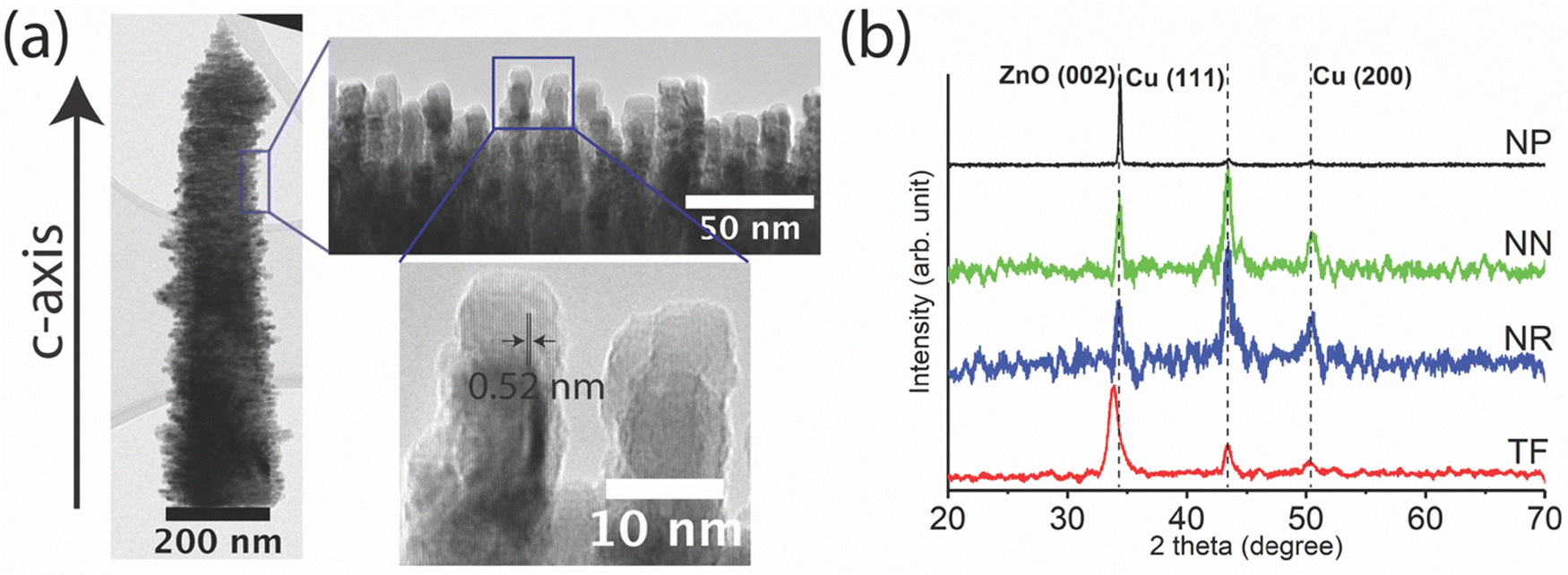 | ||
| Fig. 2 High-resolution image of the NP and crystallographic data. (a) TEM image of a single NP structure with a zoom on its protruding spikes. The main body grew along the c-axis and the spike grew perpendicular to the c-axis. The spikes are solely ZnO wurtzite crystals with a length and diameter of 30 nm and 9 nm, respectively. (b) XRD patterns of ZnO TF, NR, NN, and NP. The peaks indicate the crystallization of wurtzite ZnO with preferential (002) orientation. The Cu peaks are caused by the presence of trace copper in the S.S. substrate. | ||
Considering that the ZnO NP morphology has not previously been reported, additional characterization by XRD was warranted (Fig. 2(b)). Three main peaks in the patterns are observed at 34.5°, 43.4°, and 50.4°, which were assigned to the ZnO (002), Cu (111), and Cu (200) crystal planes, respectively.34 The latter two peaks were due to the presence of copper within the SS coupons. The first peak, on the other hand, is representative of crystal growth along the c-axis of wurtzite ZnO. The (002) peak of the thin film (TF) coating occurred at a slightly lower angle (33.9°) than for the other nanostructures, which likely results from the higher temperature and deposition energy used in the magnetron sputtering method. In addition to this difference, the full widths at half maximum (FWHMs) of the (002) peaks of the samples were not the same. The TF (002) peak had the highest FWHM (0.87°) and the FWHM of the NP was the lowest (0.174°) as compared to the rest of the samples. The FWHMs of the NNs and NRs were 0.53° and 0.22°, respectively. As the NPs were fabricated from NRs, it is thus likely that the lower FWHM (associated with larger crystal domains) was related to the protruding spikes. This strongly suggested that the spikes are highly crystalline ZnO with a wurtzite crystal structure. In fact, the lattice constant c = 0.52 nm observed by HRTEM (Fig. 2(a)) matched the d-spacing measured by XRD, which proved that the spikes are purely ZnO wurtzite that grew perpendicular to the c-axis of the nano-pillar. To test the adhesion of the spikes to the ZnO nano-pillar, NP coatings were subjected to a high-pressure tangential water flow setup. This test greatly surpassed the shear forces anticipated in any of the antibacterial assays below and was used to see whether the spikes might become dislodged during these. Fig. S2 (ESI†) shows that very minor physical damage was done to the coating, in line with other reports for ZnO NRs.35 Importantly, the spikes of the NPs remained attached to their nano-pillar base, though they showed some signs of wear in this aggressive test.
3.2. Coating topology and surface properties
The self-cleaning properties of the nano-structured surfaces in nature in part result from their ability to repel/minimize contact with water droplets and bacteria (i.e., the droplets have a greater propensity to flow off the surface and thereby reduce contact time). As these properties depend on coating topology (including the disposition and arrangement of the nanostructures), the void space between neighboring nano-pillars (colored in red in Fig. 1) was measured at both the base and at the top of the NR, NN, and NP arrays. For this, imaginary planes were drawn at the base (marked as “A”) and approximately 100 nm below the tip (marked as “B”) of the nano-pillars, and by using the pixel threshold analysis of ImageJ the total empty space was estimated. The total area was then normalized to the total surface area of the corresponding image. The results showed that the amount of empty space at the base of the nano-pillars was similar for all three arrays (∼10%), reflecting the fact that the NRs, NNs, and NPs were all grown from similar seed layers. Relative to the NRs, the empty space at the top of the NN arrays increased from 50% to 78%, due to the extension and tapering of the tips of the structures during the NR to NN step. Correspondingly, the empty space at the tops of the NP arrays decreased to 32%, due to the increased width of the nano-pillars caused by the spikes. The largest gap between the tips (edge to edge) of two neighboring nano-pillars was approximately 480 nm, 970 nm, and 350 nm for NR, NN, and NP arrays, respectively. The scale of these gaps suggested that bacteria will have more difficulty infiltrating the NP and NR arrays relative to the NN arrays. Indeed, Lin et al. have reported that nano-pillars spaced less than a cell length apart can be anti-fouling,23 and some of the dimensions above are in the right range for the bacteria investigated herein (∼0.5–2 μm).The morphological and chemical alterations to the surface of the NRs induced by the third hydrothermal step are likely to influence the bactericidal and self-cleaning properties of the coatings. Thus, coating wettability was first estimated via the contact angle formed by a small droplet of water (θ; 5 μL), slightly larger than the size produced by a sneeze (Fig. 3).36 At the nano-pillar density tested, the NR and NN coatings were much more hydrophilic (θ < 47°) than the base SS coupon (θ ∼ 90°). The increased void space of the NN coating relative to the NR coating increased wettability, as anticipated. In contrast, the θ of the NP coating was ∼90°, which made it as hydrophobic as the ZnO TF and the bare SS coupon. These results suggest that the presence of the spikes reduced the wetting of the sides of the nano-pillars by trapping air pockets between the nanoscale surface features. This phenomenon is comparable to the water-repellent properties of the water strider leg, which are caused by the hierarchical micro- and nanostructuring on the leg's surface.37 As a result of these differences, the footprint of the droplets on the different coatings differed by a factor of approximately ten from the most (TF and NP) to least (NR and NN) hydrophobic coatings.
 | ||
| Fig. 3 Wettability of the ZnO coatings. Contact angle (θ) formed by a 5-μL water droplet on ZnO coatings with different topologies. Data presented as average ± SD (n = 4; i.e., 4 drops on 4 different spots of the same coupon). | ||
The surface chemical composition of the samples was analyzed by XPS and the spectra are shown in Fig. 4(a). The peaks at 530.9 eV and 285.8 eV correspond to oxygen and carbon, respectively. The two sharp peaks at 1023.3 and 1044.3 eV are related to Zn 2p1/2 and Zn 2p3/2. These peaks are split due to spin–orbit interactions. The rest of the peaks either arise due to the Auger effect or are connected to electrons in different orbitals of zinc atoms.38 No other element was detected on the surface of the samples conveying the purity of the ZnO nanostructures prepared by this method. The high-resolution O 1s peaks of the samples are shown in Fig. 4(b). The peaks can be decomposed into two sub-spectral components at ∼530 eV and 531.5 eV. The first peak is assigned to O2− ions (OL) in a stoichiometric ratio with Zn2+, with their full complement of nearest-neighbor O2− ions. OH is connected with the O2− ions in an oxygen-deficient ZnOx region or to hydroxyl groups resulting from chemisorbed water.38 The shift in O 1s of the TF could be related to stronger Zn–O bonds, as this sample was prepared by a high-energy physical deposition technique rather than by a hydrothermal method. The surface percentage of each of the sub-peaks was approximated by spectral decomposition and the results are shown in Fig. 4(c). Based on these data, the level of lattice oxygen is the lowest for the NP coating. Nevertheless, its approximate OH surface percentage is the highest compared to the other samples. In light of these results, and to better understand how nano-pillar morphology might intrinsically influence antibacterial activity, the possible contribution of surface chemistry and photochemical reactions was tested. For this, the photoluminescence (PL) spectra of the ZnO-coated coupons are shown in Fig. 4(d). Two peaks are often recognized in the PL spectra of wurtzite ZnO NRs synthesized by the hydrothermal method.39 The first peak corresponds to the near band edge emission (NBE) of ZnO crystals and the second broad peak, which falls in the visible region, is known to be related to defect emission.39 The NBE for the NRs and NNs overlap and are located at 375 nm, while this peak is shifted to 377 nm for the NP. This small shift implies that the nano-spikes have a slightly smaller bandgap than the NRs. Thus, the spikes likely absorb light in the visible range more effectively than the NRs, albeit only very small differences in the photocatalytic activity under ambient light were observed between the coatings (Fig. 5). The NBE peak of the TF was centered at 424 nm showing that it absorbs visible light to a greater extent than the other samples. According to the PL spectra, NNs have the highest defect emission while the TF sample has almost zero defect emission. NRs and NPs have similar levels of defect emission, conveying the fact that the contribution of the spikes to defect emission was negligible. Comparing the XPS data to the defect emission peak of the PL spectrum of the NP sample, it can be concluded that higher OH percentages are related to the larger number of hydroxyl groups at the surface of the NPs and/or the O2− ions (OH) in an oxygen-deficient ZnOx region. The surface reactive groups on the coatings could be a contributing factor to bactericidal activity. Indeed, the higher percentage of OH in the NP coating increases the probability of electron capture, which could increase the propensity of inducing oxidative stress in the bacteria.40
 | ||
| Fig. 4 Surface chemical composition of the ZnO coatings and photoluminescence spectra. (a) XPS spectra; (b) decomposition and (c) results of the approximate surface percentage of OL and OH of the O 1s peaks of ZnO TF, NN, NP, and NR coatings; and (d) normalized (to near band edge emission) room temperature photoluminescence spectra. | ||
 | ||
| Fig. 5 Photodegradation of RhB by the ZnO coatings. Degradation rate constants of RhB by the ZnO coatings with and without UV irradiation (n = 4). | ||
Finally, the most straightforward manner of comparing the level of reactive oxygen species (ROS) that could be produced by the coatings is to assess their ability to degrade a model organic molecule, RhB, under both ambient and UV light. Such ROS can potentially contribute to their bactericidal properties.41 The degradation of RhB was negligible for a bare SS substrate under UV irradiation. ZnO is a semiconductor that absorbs UV light due to its relatively wide band gap. Thus, the number of excited electrons in the conduction band of ZnO is larger under UV radiation than under ambient light. Accordingly, the degradation of RhB was two orders of magnitude lower under ambient light conditions (Fig. 5), and little or no differences were observed between the nanostructured coatings, despite the chemical differences discussed above. Overall ambient light is not likely to induce bactericidal reactions for any of the coatings.
3.3. Antibacterial activity of the coatings towards S. aureus and K. pneumoniae
To test the antibacterial properties of the coatings, Gram-positive S. aureus and Gram-negative K. pneumoniae were chosen, as both are associated with hospital-acquired infections and antimicrobial resistance.42–44 In fact, the S. aureus and K. pneumoniae were among the top six pathogens responsible for 3.57 M deaths associated with antimicrobial resistance in 2019, and they have been identified as priority pathogens by the World Health Organization.1 To see how the change of void space within the coatings influenced antibacterial activity under different scenarios, the coatings were tested according to five different protocols. The first is based on ASTM 2149, which is an immersion test that completely submerges the coated coupons into the bacterial suspension. The second, ISO 22196, spreads a droplet of bacterial suspension into a thin film of constant surface area using a plastic sheet, thereby removing any effect of surface wettability. The results from both tests will inevitably reflect the relative contribution of the different putative killing mechanisms, which depend on the way the bacterial suspension interfaces with the coating. For instance, the immersion test should more prominently reflect long-range mechanisms (e.g., release and diffusion of cytotoxic compounds) while ISO 22196 should more prominently reflect short-range mechanisms (e.g., contact killing but also the sort-range release of cytotoxic compounds). As seen in Fig. 6, the bactericidal effect obtained via the ISO 22196 test (over 24 h) was very high toward both bacterial strains and was essentially independent of coating morphology. Residual bacterial cell viability was either near to or below the limit of detection in all cases. This contrasts sharply with the results obtained with the bare SS coupon, for which significant viable bacteria remained. The ASTM 2149 immersion test (24 h) showed a substantially lower bactericidal activity. Loss of viability was moderate in the case of K. pneumoniae (at most 1–2 log over 24 h), though more pronounced towards S. aureus (3–6 log over 24 h, with differences between the coatings). Globally comparing results from both tests suggest that the short-range bactericidal mechanisms of the ZnO coatings are stronger than the long-range ones.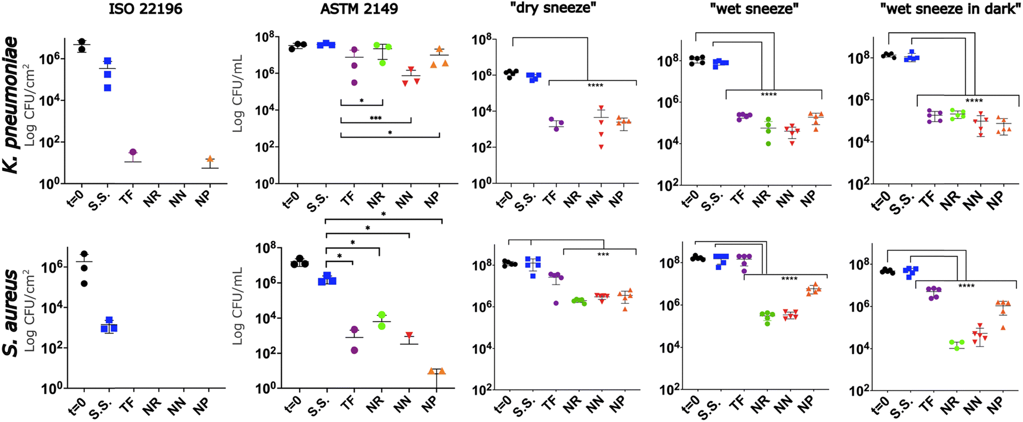 | ||
| Fig. 6 Antibacterial activity of the ZnO coatings towards S. aureus and K. pneumoniae. t = 0: initial bacterial concentration of the suspension placed on the surfaces. The absence of data for certain coatings indicates results below the limit of detection of the test employed. The y-axis title shown for the leftmost figure panes are applicable to the entire row. The error bars represent the standard deviation from the mean (n = 3–5 independent samples). Values that are significantly different are indicated by asterisks. (****, P < 0.0005; ***, P < 0.005; *, P < 0.05; ANOVA with Tukey's multiple-comparison test). The y-axis title in the second column applies to all other columns to the right. | ||
To better distinguish the antibacterial activity of the different ZnO coatings from kinetic and wettability standpoints, three additional tests were developed to emulate a 1-h exposure to a sneezed bacterial suspension droplet in either dry, wet/light, or wet/dark environments. As anticipated, these tests led to substantially higher residual bacteria viability compared to ISO 22196, due to the much shorter contact time and smaller contact area of the bacterial suspension with the coating. Globally, K. pneumoniae was more sensitive to inactivation (2–4 log reduction) than S. aureus (1–3 log reduction) in these tests. Curiously, the ZnO TF coating was bactericidal towards K. pneumoniae at a level similar to the ZnO nanostructured coatings. Differences were not observed between any of the coatings with different nanoscale topologies, even though the footprint of the bacterial droplets changed due to θ. In contrast, the bactericidal activity of ZnO TF was very low or absent towards S. aureus, confirming the importance of the morphological characteristics of the coatings on their bactericidal properties, as quantified by Jeong et al.45 Towards S. aureus, the nanostructured coatings were 1–3 log more bactericidal than ZnO TF, and an effect of morphology was observed for the wet sneeze tests, but not the dry sneeze ones. Indeed, under conditions in which the droplet could dry, the nanostructured coatings performed very similarly, yielding residual bacteria levels near or at the limit of detection of the test. Presumably, drying of the droplet promotes contact of the bacteria with the coating, which exacerbates the physical stress created by the nano-pillars. In contrast, under the wet sneeze conditions, the NP coating was less bactericidal than the other two coatings by approx. 1 log. This could be rationalized by the smaller footprint of the bacteria droplet on this hydrophobic surface relative to the hydrophilic one (about 1/10th). Indeed, the droplet was in contact with one order of magnitude (∼5.6 × 10⁸) greater number of NRs/NNs than NPs (∼5.6 × 10⁷) due to this effect. The presence/absence of ambient light, which could potentially produce ROS (vide supra) did not affect results, confirming that the ambient light-induced ROS mechanism did not contribute significantly to results under these conditions.
4. Conclusion
In summary, this work demonstrates that a third step can be added to the two-step hydrothermal synthesis method to engineer the void space within ZnO nano-pillar arrays, with a consequent effect on several coating properties. Such control could be exploited to balance the self-sanitizing and self-cleaning properties of these coatings and optimize them for a given application. The desirable properties for a coating will inevitably depend on the nature of the pathogen and the way the latter contacts the coating, and thus the additional design freedom the reported concept provides is important. This was exemplified in this proof-of-concept work by the ability to strongly alter coating hydrophobicity without compromising bactericidal performance in a variety of antibacterial assays. Future work should focus on systematically exploring the geometric parameter space available to NP arrays, to best elucidate trends for this purpose.Author contributions
A. H., A. A. G., M. A. G., M. C. G., E. D., and S. S. designed and coordinated the overall study. A. H. fabricated the samples and performed the SEM, XRD, XPS, TEM, and contact angle measurement tests. K. K. prepared the ZnO thin films under the supervision of A.R. The antibacterial tests were performed by A. A. G. and M. C. G. The photocatalytic activity measurement was performed by D. M. All authors discussed the results and commented on the manuscript. A. H. and M. A. G. coordinated the writing of the manuscript.Data availability
The data supporting this article have been included as part of the ESI.†Conflicts of interest
The authors declare no competing interests.Acknowledgements
This work was supported by the Natural Sciences and Engineering Research Council (NSERC, RGPIN-2021-03301, RGPIN-2019-07158, RGPIN-2020-06771) of Canada and the Fonds de Recherche du Québec—Nature et Technologies (FRQ-NT, 2022-PR-301076, 2022-PR-300412). A. H. acknowledges a postdoctoral scholarship from the FRQNT. M. A. G. is a Research Scholar of the FRQ-Santé.References
- C. J. Murray, K. S. Ikuta, F. Sharara, L. Swetschinski, G. R. Aguilar, A. Gray, C. Han, C. Bisignano, P. Rao and E. Wool, Lancet, 2022, 399, 629–655 CrossRef CAS PubMed.
- O. N. J, Journal, 2016, CRID 1370017282432733061.
- P. Aranega-Bou, N. Ellaby, M. J. Ellington and G. Moore, Microorganisms, 2021, 9, 1868 CrossRef CAS PubMed.
- D. J. Morgan, L. L. Lomotan, K. Agnes, L. McGrail and M.-C. Roghmann, Infect. Control Hosp. Epidemiol., 2015, 31, 864–866 CrossRef PubMed.
- B. W. Buchan, M. B. Graham, J. Lindmair-Snell, J. Arvan, N. A. Ledeboer, R. Nanchal and L. S. Munoz-Price, Am. J. Infect. Control, 2019, 47, 98–100 CrossRef PubMed.
- C. Lalancette, D. Charron, C. Laferrière, P. Dolcé, E. Déziel, M. Prévost and E. Bédard, Pathogens, 2017, 6, 36 CrossRef PubMed.
- K. U. Jansen, C. Knirsch and A. S. Anderson, Nat. Med., 2018, 24, 10–19 CrossRef CAS PubMed.
- E. Tuladhar, W. C. Hazeleger, M. Koopmans, M. H. Zwietering, R. R. Beumer and E. J. A. Duizer, Microbiology, 2012, 78, 7769–7775 CAS.
- A. Kramer, I. Schwebke and G. Kampf, BMC Infect. Dis., 2006, 6, 130 CrossRef PubMed.
- J.-L. Sagripanti and A. Bonifacino, Surg. Infect., 2000, 1, 3–14 CrossRef CAS PubMed.
- A. D. Russell, J. Hosp. Infect., 1999, 43, S57–S68 CrossRef.
- M. G. Schmidt, H. H. Attaway, P. A. Sharpe, J. John, K. A. Sepkowitz, A. Morgan, S. E. Fairey, S. Singh, L. L. Steed, J. R. Cantey, K. D. Freeman, H. T. Michels and C. D. Salgado, J. Clin. Microbiol., 2012, 50, 2217–2223 CrossRef PubMed.
- S. Rabow, M. Soares and J. Rousk, J. Appl. Ecol., 2023, 60, 237–250 CrossRef.
- A. E.-D. M. S. Hosny, S. A. Rasmy, D. S. Aboul-Magd, M. T. Kashef and Z. E. El-Bazza, Infect. Drug Resist., 2019, 12, 1985–2001 CrossRef PubMed.
- O. McNeilly, R. Mann, M. Hamidian and C. Gunawan, Front. Microbiol., 2021, 12, 652863 CrossRef PubMed.
- A. Jaggessar, H. Shahali, A. Mathew and P. K. Yarlagadda, J. Nanobiotechnol., 2017, 15, 1–20 CrossRef.
- K. H. Tam, A. B. Djurišić, C. M. N. Chan, Y. Y. Xi, C. W. Tse, Y. H. Leung, W. K. Chan, F. C. C. Leung and D. W. T. Au, Thin Solid Films, 2008, 516, 6167–6174 CrossRef CAS.
- S. Thakur and S. K. Mandal, New J. Chem., 2020, 44, 11796–11807 RSC.
- M. Ashraf, F. Dumont, C. Campagne, P. Champagne, A. Perwuelz, A. Leriche and N.-E. Chihib, J. Eng. Fibers Fabr., 2014, 9, 155892501400900103 Search PubMed.
- T. O. Okyay, R. K. Bala, H. N. Nguyen, R. Atalay, Y. Bayam and D. F. Rodrigues, RSC Adv., 2015, 5, 2568–2575 RSC.
- M. Ashraf, P. Champagne, C. Campagne, A. Perwuelz, F. Dumont and A. Leriche, J. Ind. Text., 2016, 45, 1440–1456 CrossRef CAS.
- I. Rago, C. R. Chandraiahgari, M. P. Bracciale, G. De Bellis, E. Zanni, M. Cestelli Guidi, D. Sali, A. Broggi, C. Palleschi, M. S. Sarto and D. Uccelletti, RSC Adv., 2014, 4, 56031–56040 RSC.
- N. Lin, A. Valiei, G. McKay, D. Nguyen, N. Tufenkji and C. Moraes, ACS Biomater. Sci. Eng., 2022, 8, 3122–3131 CrossRef CAS PubMed.
- O. Akhavan, M. Mehrabian, K. Mirabbaszadeh and R. Azimirad, J. Phys. D: Appl. Phys., 2009, 42, 225305 CrossRef.
- Q. Cai, Y. Gao, T. Gao, S. Lan, O. Simalou, X. Zhou, Y. Zhang, C. Harnoode, G. Gao and A. Dong, ACS Appl. Mater. Interfaces, 2016, 8, 10109–10120 CrossRef CAS PubMed.
- M. F. Elkady, H. Shokry Hassan, E. E. Hafez and A. Fouad, Bioinorg. Chem. Appl., 2015, 2015, 536854 CAS.
- N. Lin, G. McKay, D. Nguyen, C. Moraes and N. Tufenkji, ACS Appl. Nano Mater., 2023, 6, 18454–18465 CrossRef CAS.
- Y. Xie, X. Qu, J. Li, D. Li, W. Wei, D. Hui, Q. Zhang, F. Meng, H. Yin, X. Xu, Y. Wang, L. Wang and Z. Zhou, Sci. Total Environ., 2020, 738, 139714 CrossRef CAS PubMed.
- L. Zhao, T. Liu, X. Li, Q. Cui, X. Wang, K. Song, D. Ge and W. Li, ACS Biomater. Sci. Eng., 2023, 9, 4770–4780 CrossRef CAS.
- U. Anand, T. Ghosh, Z. Aabdin, S. Koneti, X. Xu, F. Holsteyns and U. Mirsaidov, Proc. Natl. Acad. Sci. U. S. A., 2021, 118, e2108074118 CrossRef CAS.
- A. Uneputty, A. Dávila-Lezama, D. Garibo, A. Oknianska, N. Bogdanchikova, J. F. Hernández-Sánchez and A. Susarrey-Arce, Colloid Interface Sci. Commun., 2022, 46, 100560 CrossRef CAS.
- J. Zhang, G. Williams, T. Jitniyom, N. S. Singh, A. Saal, L. Riordan, M. Berrow, J. Churm, M. Banzhaf, F. de Cogan and N. Gao, Langmuir, 2024, 40, 7353–7363 CrossRef CAS PubMed.
- S. N. Riduan, G. Yi, S. Gao, J. P. K. Tan, Y. L. Tan, Y. Yuan, H. Lu, S. Chng, J. T. Ong and P. Y. Hon, ACS Appl. Bio Mater., 2021, 4, 7524–7531 CrossRef CAS PubMed.
- T. Theivasanthi and M. Alagar, arXiv, 2010, preprint arXiv:1003.6068 DOI:10.48550/arXiv.1003.6068.
- S. N. Riduan, G. Yi, S. Gao, J. P. K. Tan, Y. L. Tan, Y. Yuan, H. Lu, S. Chng, J. T. Ong, P. Y. Hon, M. Y. Abdad, S. Vasoo, B. S. P. Ang, Y. Y. Yang, J. Y. Ying and Y. Zhang, ACS Appl. Bio Mater., 2021, 4, 7524–7531 CrossRef CAS PubMed.
- Z. Y. Han, W. G. Weng and Q. Y. Huang, J. R. Soc., Interface, 2013, 10, 20130560 CrossRef CAS PubMed.
- X. Gao and L. Jiang, Nature, 2004, 432, 36 CrossRef CAS PubMed.
- A. Hassanpour, P. Guo, S. Shen and P. Bianucci, Nanotechnology, 2017, 28, 435707 CrossRef CAS PubMed.
- A. Hassanpour, N. Bogdan, J. A. Capobianco and P. Bianucci, Mater. Des., 2017, 119, 464–469 CrossRef CAS.
- H. Yang, C. Liu, D. Yang, H. Zhang and Z. Xi, J. Appl. Toxicol., 2009, 29, 69–78 CrossRef CAS PubMed.
- G. Applerot, A. Lipovsky, R. Dror, N. Perkas, Y. Nitzan, R. Lubart and A. Gedanken, Adv. Funct. Mater., 2009, 19, 842–852 CrossRef CAS.
- L. Tian, Z. Sun and Z. Zhang, BMC Public Health, 2018, 18, 1121 CrossRef CAS PubMed.
- D. B. Thuy, J. Campbell, C. T. Thuy, N. V. M. Hoang, P. Voong Vinh, T. N. T. Nguyen, C. Nguyen Ngoc Minh, D. T. Pham, M. A. Rabaa, N. P. H. Lan, N. V. Hao, G. E. Thwaites, C. L. Thwaites, S. Baker, N. V. V. Chau and H. Chung The, Microb. Genomics, 2021, 7, 000514 CAS.
- C. N. I. Surveillance, Can. Commun. Dis. Rep., 2020, 46, 99–112 CrossRef PubMed.
- E. Jeong, C. U. Kim, J. Byun, J. Lee, H.-E. Kim, E.-J. Kim, K. J. Choi and S. W. Hong, Sci. Total Environ., 2020, 712, 136574 CrossRef CAS PubMed.
Footnote |
| † Electronic supplementary information (ESI) available. See DOI: https://doi.org/10.1039/d5ma00180c |
| This journal is © The Royal Society of Chemistry 2025 |