 Open Access Article
Creative Commons Attribution 3.0 Unported Licence
Functional separator with a nitrogen/oxygen-rich interlayer for enhancing performance of Li–S batteries
Ying Guo,
Justin Zhong,
Jin Liu * and
Wei-Hong Zhong
 *
*
School of Mechanical and Materials Engineering, Washington State University, Pullman, WA 99164, USA. E-mail: jin.liu2@wsu.edu; katie_zhong@wsu.edu
First published on 26th September 2025
Abstract
Lithium–sulfur (Li–S) batteries have attracted considerable attention due to their high theoretical energy density. However, their practical application is hindered by critical issues, including uneven lithium deposition and polysulfide shuttling. To address these critical issues, surface functionalization with nitrogen- (N-) and oxygen- (O-) containing polar groups has proven effective in stabilizing battery interfaces by suppressing polysulfide migration and promoting uniform lithium deposition. Here, we propose a facile strategy to construct an N- and O-rich interlayer via a simple one-step hydrolysis process. The resulting hydrolyzed polyacrylonitrile–poly(vinylidene fluoride-co-hexafluoropropylene) interlayer introduces abundant N- and O-containing polar groups onto a commercial separator (CS) to form the modified separator N–O@CS, which exhibits enhanced electrolyte wettability, mechanical strength, and electronic polarizability, thereby effectively regulating polysulfide migration and lithium deposition. Specifically, at 0.2 A g−1, the cells achieve a high capacity of 675.5 mAh g−1 with a retention of 95.3% after 200 cycles, outperforming those with CS (468 mAh g−1, 72%) and N@CS (603 mAh g−1, 90.1%). Furthermore, at a higher current density of 0.5 A g−1, the cell with N–O@CS retains 62.3% of its initial capacity after 600 cycles. This study offers a simple and effective strategy to fabricate high-performance Li–S batteries.
1. Introduction
Lithium–sulfur (Li–S) batteries are among the most promising candidates for high-energy storage systems, owing to their high theoretical energy density (2600 Wh kg−1) and specific capacity (1675 mAh g−1).1 Moreover, sulfur is naturally abundant and environmentally benign, making it an attractive cathode material for Li–S batteries. Despite these advantages, several challenges hinder the practical application of Li–S batteries, including the polysulfide shuttle effect and lithium dendrite growth.2 Soluble lithium polysulfides (Li2Sn, 4 ≤ n ≤ 8) generated during cycling can shuttle between the sulfur cathode and lithium anode, leading to severe loss of the active materials, low coulombic efficiency, and poor cycling stability.3,4 In addition, uneven lithium deposition on the anode results in dendrite formation, which not only degrades battery performance but also poses serious safety risks.5To address the challenges of Li–S batteries, extensive efforts have been devoted to modifying key components such as binders,6,7 separators,8,9 and electrolytes10,11 to enhance overall performance. These functionalized components can effectively trap lithium polysulfides and regulate the deposition/transport of lithium ions. Among them, the binder plays a critical role in maintaining electrode integrity by ensuring good adhesion between active and conductive materials, even though it is a small portion of the cathode (<10 wt%). To endow binders with chemical functionality for polysulfide adsorption, various alternatives to conventional poly(vinylidene difluoride) have been investigated, including sodium carboxymethylcellulose,12 poly(acrylic acid),13 and even natural protein-based materials with abundant functional groups such as –OH, –COOH, etc.14 While these functional binders have shown promise in mitigating the shuttle effect, their influence is largely confined to the cathode side and has limited impact on suppressing lithium dendrite formation at the anode.
In contrast, the separator, which interfaces with both the sulfur cathode and lithium anode, offers a more comprehensive solution. By modifying the separator, it is possible to simultaneously inhibit polysulfide migration and suppress lithium dendrite growth.15–17 Among various separator engineering approaches, surface functionalization via incorporating polar functional groups with nitrogen (N) and/or oxygen (O) atoms has shown great promise for interfacial stabilization. These groups play a synergistic role in enhancing the interfacial stability of Li–S batteries. N-based groups (e.g., –C![[triple bond, length as m-dash]](https://www.rsc.org/images/entities/char_e002.gif) N and –NH2) can coordinate with lithium ions and chemically anchor lithium polysulfides through Lewis acid–base interactions, thereby suppressing their diffusion to the anode. O-based groups (e.g., –COOH and –C
N and –NH2) can coordinate with lithium ions and chemically anchor lithium polysulfides through Lewis acid–base interactions, thereby suppressing their diffusion to the anode. O-based groups (e.g., –COOH and –C![[double bond, length as m-dash]](https://www.rsc.org/images/entities/char_e001.gif) O) improve electrolyte wettability and promote uniform lithium-ion transport, facilitating homogeneous lithium deposition. Both computational and experimental studies have demonstrated that these polar functional groups containing N/O increase the binding energy with lithium polysulfides, effectively mitigating the shuttle effect.18,19 To leverage these advantages, a variety of N/O-rich materials have been explored, including functionalized polymers (e.g., polyvinylpyrrolidone and polyimide),20,21 natural macromolecules (e.g., soy protein and corn protein),22,23 and functional group-enriched carbon materials such as heteroatom-doped graphene,24 MOFs,25 and single-atom catalysts.26 However, in polymer-based materials, these functional groups are often embedded within the polymer chains, which limits their effective interactions with lithium ions or polysulfides. Additionally, incorporation of such functional groups often requires complex chemical reactions, high-temperature treatments, and/or time-consuming synthesis procedures. These challenges highlight the urgent need for more sustainable and facile strategies to introduce N- and O-containing functional groups onto separator and binder systems for advanced Li–S batteries. Among the materials explored for introducing N- and O-containing functional groups, polyacrylonitrile (PAN) stands out due to its intrinsic N-rich structure and excellent film-forming properties.27 The nitrile group (–C
O) improve electrolyte wettability and promote uniform lithium-ion transport, facilitating homogeneous lithium deposition. Both computational and experimental studies have demonstrated that these polar functional groups containing N/O increase the binding energy with lithium polysulfides, effectively mitigating the shuttle effect.18,19 To leverage these advantages, a variety of N/O-rich materials have been explored, including functionalized polymers (e.g., polyvinylpyrrolidone and polyimide),20,21 natural macromolecules (e.g., soy protein and corn protein),22,23 and functional group-enriched carbon materials such as heteroatom-doped graphene,24 MOFs,25 and single-atom catalysts.26 However, in polymer-based materials, these functional groups are often embedded within the polymer chains, which limits their effective interactions with lithium ions or polysulfides. Additionally, incorporation of such functional groups often requires complex chemical reactions, high-temperature treatments, and/or time-consuming synthesis procedures. These challenges highlight the urgent need for more sustainable and facile strategies to introduce N- and O-containing functional groups onto separator and binder systems for advanced Li–S batteries. Among the materials explored for introducing N- and O-containing functional groups, polyacrylonitrile (PAN) stands out due to its intrinsic N-rich structure and excellent film-forming properties.27 The nitrile group (–C![[triple bond, length as m-dash]](https://www.rsc.org/images/entities/char_e002.gif) N) in PAN is particularly well-suited for anchoring lithium polysulfides and facilitating the introduction of additional functional groups. Furthermore, PAN can undergo a simple one-step hydrolysis that introduces both N- and O-containing polar groups (e.g., –CONH2 and –COOH), thereby enhancing the surface chemistry in a highly efficient manner.28 However, this facile, scalable modification process has not yet been realized to enable the development of functional interfacial layers without the need for complex synthesis or high-temperature treatments.
N) in PAN is particularly well-suited for anchoring lithium polysulfides and facilitating the introduction of additional functional groups. Furthermore, PAN can undergo a simple one-step hydrolysis that introduces both N- and O-containing polar groups (e.g., –CONH2 and –COOH), thereby enhancing the surface chemistry in a highly efficient manner.28 However, this facile, scalable modification process has not yet been realized to enable the development of functional interfacial layers without the need for complex synthesis or high-temperature treatments.
In this study, a functional separator is successfully fabricated via a simple one-step hydrolysis process to address the key interfacial challenges of Li–S batteries on both the cathode and anode sides. The separator is modified with a hydrolyzed polyacrylonitrile–poly(vinylidene fluoride-co-hexafluoropropylene) (N–O@CS) separator, which introduces abundant N- and O-containing functional groups. The resulting separator exhibits improved electrolyte wettability, enhanced mechanical strength, and increased electronic polarizability. As a result, the Li–S batteries assembled with the N–O@CS separator exhibit regulated lithium deposition and suppressed polysulfide shuttling, leading to improved electrochemical performance Specifically, at a current density of 0.2 A g−1, the cells achieve a high capacity of 675.5 mAh g−1 with a remarkable retention of 95.3% after 200 cycles, outperforming those with CS (468 mAh g−1, 72%) and N@CS (603 mAh g−1, 90.1%).Furthermore, it exhibits a high capacity of 440 mAh g−1 with a retention of 62.3% after 600 cycles at a current density of 0.5 A g−1.
2. Experimental
2.1 Materials
Soy protein (SP) and polyacrylonitrile (PAN, Mw = 1.5 × 10⁵) were obtained from Archer Daniels Midland Co., Ltd. Polyethylene oxide (PEO, Mw = 4 × 10⁶) was purchased from Millipore Sigma. Acetic acid was supplied by VWR Corporation. Poly(vinylidene fluoride-co-hexafluoropropylene) (PHFP), dimethyl sulfoxide (DMSO) and the active material (sulfur powder, S) were purchased from Sigma-Aldrich Co., Ltd. 1,3-Dioxolane (DOL), dimethoxyethane (DME), and lithium nitrate (LiNO3) were also obtained from Sigma-Aldrich Co., Ltd. Lithium bis(trifluoromethanesulfonimide) (LiTFSI) and lithium sulfide (Li2S) were purchased from Thermo Fisher Scientific Inc. Graphene nanopowder (C, 99.5+%, 1–5 nm) was brought from SkySpring Nanomaterials, Inc. Electrode components, including carbon-coated Al foil, Celgard 2325 separators, and the conductive additive (carbon black, Super C45) were produced from MTI Co., Ltd.2.2 Sample preparation
![[thin space (1/6-em)]](https://www.rsc.org/images/entities/char_2009.gif) :
:![[thin space (1/6-em)]](https://www.rsc.org/images/entities/char_2009.gif) 10 (PAN
10 (PAN![[thin space (1/6-em)]](https://www.rsc.org/images/entities/char_2009.gif) :
:![[thin space (1/6-em)]](https://www.rsc.org/images/entities/char_2009.gif) PHFP) and stirred at 25 °C for 12 h to form a homogeneous solution. The resulting solution was then cast onto both sides of a commercial Celgard separator, forming a uniform coating with a thickness of approximately 25.4 μm per side. The modified separator was subsequently dried at room temperature for 12 h.
PHFP) and stirred at 25 °C for 12 h to form a homogeneous solution. The resulting solution was then cast onto both sides of a commercial Celgard separator, forming a uniform coating with a thickness of approximately 25.4 μm per side. The modified separator was subsequently dried at room temperature for 12 h.![[thin space (1/6-em)]](https://www.rsc.org/images/entities/char_2009.gif) :
:![[thin space (1/6-em)]](https://www.rsc.org/images/entities/char_2009.gif) 1, w/w) at 90 °C for 1 h to obtain an unfolded structure. After cooling to room temperature, 0.001 g of graphene (Gr) was introduced, followed by the gradual addition of poly(ethylene oxide) (PEO). The mixture was stirred for 4 h to form the interpenetrated SP–PEO–Gr binder, in which the unfolded SP structure was effectively stabilized, and more functional groups were exposed. Subsequently, sulfur (S) and carbon black were incorporated into the prepared binder system and stirred for 24 h to obtain a homogeneous slurry.
1, w/w) at 90 °C for 1 h to obtain an unfolded structure. After cooling to room temperature, 0.001 g of graphene (Gr) was introduced, followed by the gradual addition of poly(ethylene oxide) (PEO). The mixture was stirred for 4 h to form the interpenetrated SP–PEO–Gr binder, in which the unfolded SP structure was effectively stabilized, and more functional groups were exposed. Subsequently, sulfur (S) and carbon black were incorporated into the prepared binder system and stirred for 24 h to obtain a homogeneous slurry.![[thin space (1/6-em)]](https://www.rsc.org/images/entities/char_2009.gif) :
:![[thin space (1/6-em)]](https://www.rsc.org/images/entities/char_2009.gif) 1 v/v) solvent mixture. The sulfur cathode was fabricated using a slurry of sulfur, carbon black, and SP–PEO–Gr binder in a weight ratio of 67.5
1 v/v) solvent mixture. The sulfur cathode was fabricated using a slurry of sulfur, carbon black, and SP–PEO–Gr binder in a weight ratio of 67.5![[thin space (1/6-em)]](https://www.rsc.org/images/entities/char_2009.gif) :
:![[thin space (1/6-em)]](https://www.rsc.org/images/entities/char_2009.gif) 22.5
22.5![[thin space (1/6-em)]](https://www.rsc.org/images/entities/char_2009.gif) :
:![[thin space (1/6-em)]](https://www.rsc.org/images/entities/char_2009.gif) 10. The typical sulfur loading was between 1.0 and 1.5 mg cm−2.
10. The typical sulfur loading was between 1.0 and 1.5 mg cm−2.2.3 Material characterization
The surface morphologies of the commercial separator, N@CS separator, and N–O@CS separator were examined using scanning electron microscopy (SEM, Apreo) with integrated energy dispersive X-ray spectroscopy (EDS). The chemical structures of the samples were analyzed by Fourier transform infrared spectroscopy with attenuated total reflectance (FTIR-ATR, Thermo Fisher iS10) with a scan resolution of 0.5 cm−1. The wettability of the separators was evaluated via contact angle measurements using an optical contact angle analyzer (OCA 15 plus, Dataphysics Instruments, SCA20). The composition ratio of each sample was determined via thermogravimetric analysis (TGA, SDT Q600, Switzerland), conducted under a nitrogen atmosphere from 25 °C to 800 °C at a heating rate of 5 °C min−1. The mechanical properties of the separators were characterized using a dynamic mechanical analyzer (DMA, Q800) in tensile mode at a strain rate of 30.00% min−1. The dielectric measurements were carried out on a high-resolution dielectric analyzer (Novocontrol Technologies Alpha-N, Germany).2.4 Electrochemical characterization
The galvanostatic charge/discharge profiles, cycling stability, and rate performance of Li–S batteries were evaluated using a battery analyzer (BST8-MA, MTI) within a voltage range of 1.8–2.8 V. Electrochemical impedance spectroscopy (EIS) was carried out on an electrochemical workstation (Bio-Logic VSP, EC-Lab) in the frequency range of 0.01 Hz to 1 MHz. Cyclic voltammetry (1.8–2.8 V, 0.1–0.5 mV s−1) was also conducted using the same workstation.3. Results and discussion
The working mechanism of the N–O@CS separator is illustrated in Fig. 1. As shown in Fig. 1a, the Li–S cell employing a CS suffers from poor electrochemical performance due to the absence of polar functional groups. This lack of polarity provides little resistance to the diffusion of soluble lithium polysulfides and fails to regulate lithium-ion transport. As a result, uncontrolled polysulfide migration leads to a severe shuttle effect, loss of active material, and rapid capacity fading. Moreover, the unregulated lithium-ion flux contributes to inhomogeneous lithium deposition and dendritic growth, posing serious safety concerns. In contrast, the N–O@CS separator introduces a multifunctional interfacial layer enriched with polar functional groups, as shown in Fig. 1b. These groups exhibit strong intermolecular interactions with lithium polysulfides via polar–polar interactions, hydrogen bonding, and possible Lewis acid–base interactions, thereby immobilizing polysulfides and suppressing their diffusion. Furthermore, the polar functional groups help regulate lithium-ion transport, leading to more uniform lithium deposition and better cycling stability.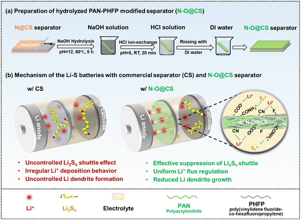 | ||
| Fig. 1 (a) Schematic illustration of preparation processes of the N–O@CS separator and (b) comparison of the working mechanisms of CS and N–O@CS separators in Li–S batteries. | ||
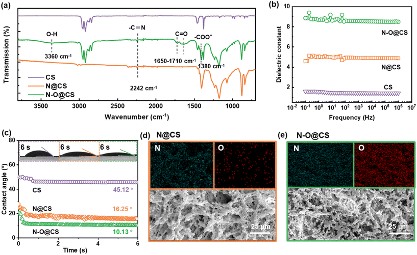
Fig. 2 presents the structural and physicochemical characterization of the N@CS and N–O@CS separators. As shown in the FTIR spectra (Fig. 2a), the successful hydrolysis of N@CS is evidenced by the emergence of a strong absorption band within 1720–1380 cm−1 and near 3360 cm−1, which is attributed to the stretching vibration of the –C![[double bond, length as m-dash]](https://www.rsc.org/images/entities/char_e001.gif) O bond and –OH in carboxylic acid groups (–COOH).28 Meanwhile, the characteristic peak of the –CN group at 2240 cm−1 is retained after hydrolysis, indicating the coexistence of O- and N-containing functional groups in N–O@CS. To evaluate the electronic polarizability and lithium-ion solvation capacity of the separators, the apparent dielectric constant (εr) of the separator materials was measured (Fig. 2b). The N–O@CS separator exhibits a significantly higher apparent dielectric constant (∼8.6) compared to the pristine N@CS (∼5.2) and commercial CS separators (∼1.5), indicating a stronger polarity and enhanced ion–dipole interactions. This improvement is mainly attributed to the introduction of polar carboxyl groups, which increase the overall dipole moment of the polymer matrix and facilitate better solvation of lithium ions, thereby promoting efficient ion transport and polysulfide anchoring. This high εr environment is beneficial for dissociating lithium salts and stabilizing lithium-ion transport, which can alleviate ion concentration gradients and promote uniform lithium-ion flux. Fig. 2c displays the electrolyte contact angles and dynamic wetting behavior on the separator surfaces. As time progresses, the contact angle of the electrolyte droplet on N–O@CS decreases rapidly and reaches ∼10° after 6 s, which is lower than that on N@CS (∼16°) and CS (∼45°). This markedly improved wettability reflects the enhanced electrolyte affinity of N–O@CS. This is primarily attributed to the introduction of hydrophilic groups (e.g., –CONH2 and –COOH), which improve electrolyte infiltration and promote stable electrolyte/separator interfaces.
O bond and –OH in carboxylic acid groups (–COOH).28 Meanwhile, the characteristic peak of the –CN group at 2240 cm−1 is retained after hydrolysis, indicating the coexistence of O- and N-containing functional groups in N–O@CS. To evaluate the electronic polarizability and lithium-ion solvation capacity of the separators, the apparent dielectric constant (εr) of the separator materials was measured (Fig. 2b). The N–O@CS separator exhibits a significantly higher apparent dielectric constant (∼8.6) compared to the pristine N@CS (∼5.2) and commercial CS separators (∼1.5), indicating a stronger polarity and enhanced ion–dipole interactions. This improvement is mainly attributed to the introduction of polar carboxyl groups, which increase the overall dipole moment of the polymer matrix and facilitate better solvation of lithium ions, thereby promoting efficient ion transport and polysulfide anchoring. This high εr environment is beneficial for dissociating lithium salts and stabilizing lithium-ion transport, which can alleviate ion concentration gradients and promote uniform lithium-ion flux. Fig. 2c displays the electrolyte contact angles and dynamic wetting behavior on the separator surfaces. As time progresses, the contact angle of the electrolyte droplet on N–O@CS decreases rapidly and reaches ∼10° after 6 s, which is lower than that on N@CS (∼16°) and CS (∼45°). This markedly improved wettability reflects the enhanced electrolyte affinity of N–O@CS. This is primarily attributed to the introduction of hydrophilic groups (e.g., –CONH2 and –COOH), which improve electrolyte infiltration and promote stable electrolyte/separator interfaces.
To further confirm the success of PAN hydrolysis, elemental mapping via energy-dispersive X-ray spectroscopy (EDS) was conducted to analyze the distribution of N and O elements on the separator surfaces. As shown in Fig. 2d and e, the N@CS separator exhibits a uniform distribution of N and a sparse presence of O, which is attributed to residual moisture or environmental oxygen exposure. In contrast, the N–O@CS separator after alkaline hydrolysis displays a greatly increased and more uniform distribution of O signals. This substantial enhancement in O content provides direct evidence for the successful hydrolysis of PAN and the subsequent introduction of polar carboxyl groups (such as –COOH and –CONH2) into the polymer matrix. Furthermore, the resulting separator surface features a co-existence of N and O elements, forming a N/O co-functionalized interface. Such a chemically enriched surface enables higher polarity and improved affinity toward lithium ions and polysulfides, thereby enhancing electrochemical performance.
To evaluate the mechanical properties of the N–O@CS separator, tensile tests were conducted. As shown in Fig. S1, the CS separator exhibits a tensile strength of approximately 10.51 MPa and breaks at a strain of 35.89%, indicating good strength but limited elongation, characteristic of a relatively brittle material. In contrast, the N–O@CS separator demonstrates an enhanced tensile strength of about 12.59 MPa and a significantly higher elongation at a break of 90%, reflecting improved ductility and toughness. These enhancements are attributed to the synergistic mechanical properties of PAN and PHFP in the composite structure. Thermogravimetric analysis (TGA) was conducted from 25 °C to 800 °C under a nitrogen atmosphere to evaluate the thermal stability of the N–O@CS separator, as shown in Fig. S2. The TGA curve exhibits three distinct stages of weight loss. The initial slight weight loss (3–5%) observed below 180 °C is attributed to the evaporation of free and bound water. As the temperature increases to around 250 °C, functional groups such as –CN, –COOH, and –C![[double bond, length as m-dash]](https://www.rsc.org/images/entities/char_e001.gif) O begin to decompose, corresponding to the partial degradation of the PAN-based matrix. With a further temperature increase above 400 °C, significant weight loss is observed due to the decomposition of the PHFP backbone and other carbon-containing components in the separator. A major degradation stage occurs between 450 °C and 600 °C, indicating the collapse of the polymer structure. Notably, a residual mass of approximately 14.4% remains at 800 °C, suggesting the formation of stable carbonaceous residues. These results confirm that the N–O@CS separator possesses good thermal stability, which is beneficial for ensuring the safety and reliability of Li–S batteries under high-temperature operating conditions.
O begin to decompose, corresponding to the partial degradation of the PAN-based matrix. With a further temperature increase above 400 °C, significant weight loss is observed due to the decomposition of the PHFP backbone and other carbon-containing components in the separator. A major degradation stage occurs between 450 °C and 600 °C, indicating the collapse of the polymer structure. Notably, a residual mass of approximately 14.4% remains at 800 °C, suggesting the formation of stable carbonaceous residues. These results confirm that the N–O@CS separator possesses good thermal stability, which is beneficial for ensuring the safety and reliability of Li–S batteries under high-temperature operating conditions.
Fig. 3 illustrates the polysulfide diffusion behavior in H-type glass cells equipped with three different separators: CS, N@CS, and N–O@CS. In this diffusion test, 5 mL of 0.5 M Li2S8 solution was placed in the left chamber and 5 mL of DOL/DME (1![[thin space (1/6-em)]](https://www.rsc.org/images/entities/char_2009.gif) :
:![[thin space (1/6-em)]](https://www.rsc.org/images/entities/char_2009.gif) 1, v/v) in the right chamber. The diffusion process was visually monitored through the color changes in the right chamber over time. After 15 minutes, the cell with the CS separator exhibited pronounced polysulfide diffusion, as evidenced by the rapid yellowing of the right chamber. The N@CS separator slightly delayed this process, with the right chamber showing a light-yellow tint. In contrast, the N–O@CS separator demonstrated a strong suppression effect, with the right chamber remaining almost colorless and only a faint yellow hue appearing at the interface. After 75 minutes, these differences became even more pronounced. The right chamber of the CS-separated cell turned dark yellow, indicating severe polysulfide diffusion. The N@CS separator offered moderate mitigation, with the right chamber appearing pale yellow. Notably, the N–O@CS separator continued to effectively inhibit Li2S8 migration, maintaining a nearly transparent right chamber with a slight yellow hue. To further clarify the separator performance, the long-term diffusion test was performed as shown in Fig. S3. A small vial containing the 50 mM Li2S8 solution was sealed with the test separator, which was mounted over a small hole drilled into the vial's cap. The vial was then inverted into a larger container filled with electrolyte to simulate prolonged diffusion. After 20 h, the CS separator allowed severe polysulfide permeation, turning the outer solution distinctly yellow. After 26 h, the N@CS separator showed slight improvement, with the outer solution appearing light yellow. In contrast, the N–O@CS separator effectively suppressed polysulfide crossover, keeping the outer solution nearly colorless throughout the test. The outer solution was then collected, diluted tenfold, and analyzed by UV-vis spectroscopy. The N–O@CS sample exhibited a markedly lower absorbance peak, confirming its stronger Li2S8 anchoring capability compared with the CS separator. During fabrication, hydrolysis introduces additional polar O-containing groups (–COOH and –CONH2) into the PAN matrix. The coexistence of O and N heteroatoms enables synergistic interactions with lithium polysulfides through dipole–ion interactions and hydrogen bonding. Compared with nitrogen alone, this dual-heteroatom system provides a stronger and more diverse binding environment, effectively immobilizing polysulfides and reducing their diffusion across the separator. Moreover, beyond its physical barrier properties, the PHFP matrix contributes additional chemical affinity, as the –CF2– groups exhibit favorable interactions with polysulfides.22 The combination of dual-heteroatom binding and –CF2– polysulfide affinity enables the superior shuttle-suppression capability of the N–O@CS separator.
1, v/v) in the right chamber. The diffusion process was visually monitored through the color changes in the right chamber over time. After 15 minutes, the cell with the CS separator exhibited pronounced polysulfide diffusion, as evidenced by the rapid yellowing of the right chamber. The N@CS separator slightly delayed this process, with the right chamber showing a light-yellow tint. In contrast, the N–O@CS separator demonstrated a strong suppression effect, with the right chamber remaining almost colorless and only a faint yellow hue appearing at the interface. After 75 minutes, these differences became even more pronounced. The right chamber of the CS-separated cell turned dark yellow, indicating severe polysulfide diffusion. The N@CS separator offered moderate mitigation, with the right chamber appearing pale yellow. Notably, the N–O@CS separator continued to effectively inhibit Li2S8 migration, maintaining a nearly transparent right chamber with a slight yellow hue. To further clarify the separator performance, the long-term diffusion test was performed as shown in Fig. S3. A small vial containing the 50 mM Li2S8 solution was sealed with the test separator, which was mounted over a small hole drilled into the vial's cap. The vial was then inverted into a larger container filled with electrolyte to simulate prolonged diffusion. After 20 h, the CS separator allowed severe polysulfide permeation, turning the outer solution distinctly yellow. After 26 h, the N@CS separator showed slight improvement, with the outer solution appearing light yellow. In contrast, the N–O@CS separator effectively suppressed polysulfide crossover, keeping the outer solution nearly colorless throughout the test. The outer solution was then collected, diluted tenfold, and analyzed by UV-vis spectroscopy. The N–O@CS sample exhibited a markedly lower absorbance peak, confirming its stronger Li2S8 anchoring capability compared with the CS separator. During fabrication, hydrolysis introduces additional polar O-containing groups (–COOH and –CONH2) into the PAN matrix. The coexistence of O and N heteroatoms enables synergistic interactions with lithium polysulfides through dipole–ion interactions and hydrogen bonding. Compared with nitrogen alone, this dual-heteroatom system provides a stronger and more diverse binding environment, effectively immobilizing polysulfides and reducing their diffusion across the separator. Moreover, beyond its physical barrier properties, the PHFP matrix contributes additional chemical affinity, as the –CF2– groups exhibit favorable interactions with polysulfides.22 The combination of dual-heteroatom binding and –CF2– polysulfide affinity enables the superior shuttle-suppression capability of the N–O@CS separator.
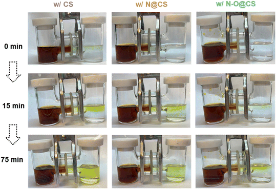 | ||
| Fig. 3 Polysulfide diffusion test for the CS separator, N@CS separator, and N–O@CS separator with 0.5 M Li2S8, after diffusion for 15 and 75 minutes. | ||
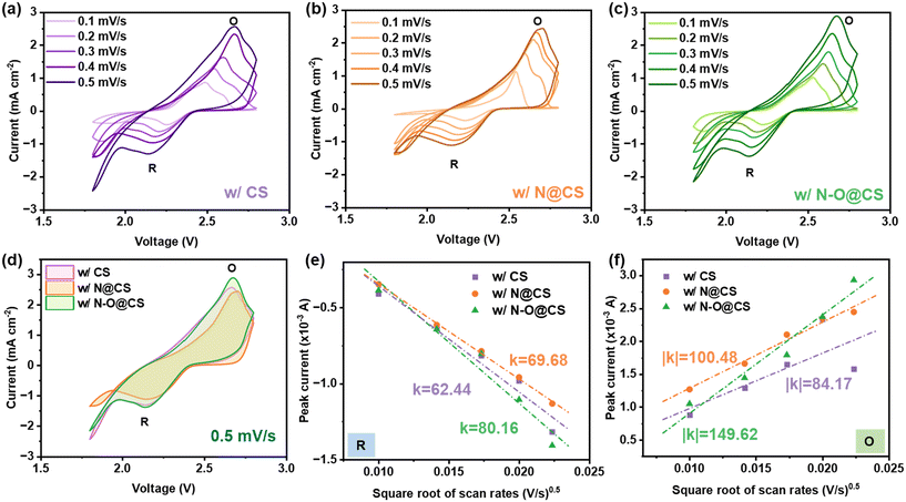
Fig. 4 presents the cyclic voltammetry (CV) curves of Li–S cells assembled with CS, N@CS, and N–O@CS separators, measured over a voltage range of 1.8–2.8 V at scan rates from 0.1 to 0.5 mV s−1. All cells exhibit distinct redox peaks. The cathodic peak (denoted as R, ∼2.2–2.3 V) corresponds to the reduction of elemental sulfur (S8) to higher-order lithium polysulfides (Li2Sn, 4 ≤ n ≤ 8), followed by further reduction to Li2S2/Li2S at 1.7–1.9 V, while the anodic peak (denoted as O, ∼2.4–2.7 V) reflects the reverse oxidation of Li2Sn to S8.29,30 As shown in Fig. 4a–c, increasing scan rates lead to a rise in peak current and a slight shift in peak potentials, indicating typical diffusion-controlled redox behavior. Fig. 4d compares the CV curves at a scan rate of 0.5 mV s−1, where the N–O@CS separator yields the highest peak currents and the largest integrated area (1.16) compared to the N@CS separator (1.11) and CS separator (1.13), indicating enhanced redox kinetics. Moreover, the sharper redox peaks observed with the N–O@CS separator suggest improved sulfur utilization and a more efficient polysulfide conversion process. To further evaluate the lithium-ion diffusion behavior associated with different separators, the linear relationship between peak current and the square root of scan rate was analyzed based on the Randles–Ševčík equation,31,32 as shown in Fig. 4e and f. The N–O@CS separator exhibits the highest slope for both the anodic (k = 149.62) and cathodic (|k| = 80.16) processes, outperforming the N@CS (k = 100.48, |k| = 69.68) and CS separators (k = 84.17, |k| = 62.44). The greater slopes indicate faster lithium-ion diffusion and enhanced electrochemical kinetics. These results confirm that the N–O@CS separator effectively promotes the redox kinetics of polysulfide conversion in Li–S batteries.
After the CV tests, the surface morphologies of the corresponding lithium metal anodes were examined using SEM, as shown in Fig. 5. The anode paired with the CS separator (Fig. 5a) exhibits a rough and uneven surface with noticeable protrusions, indicating inhomogeneous lithium deposition during cycling. In contrast, the N@CS separator leads to a smoother morphology, suggesting improved deposition behavior (Fig. 5b). Notably, the anode cycled with the N–O@CS separator displays a relatively flat and uniform surface, demonstrating the most effective suppression of lithium dendrite growth (Fig. 5c). This improvement is attributed to the presence of N- and O-containing functional groups in the interlayer, which facilitate more uniform lithium-ion flux and contribute to stabilized interfacial lithium deposition.
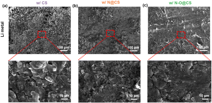 | ||
| Fig. 5 SEM images of Li metal anodes after CV tests at a scan rate of 0.1–0.5 mV s−1. Surface morphologies of Li metal anodes cycled with (a) CS, (b) N@CS, and (c) N–O@CS separators. | ||
Symmetric Li|Li cells assembled with CS, N@CS, and N–O@CS separators were evaluated to investigate their electrochemical stability, as shown in Fig. 6. The cell with the CS exhibits higher overpotentials at current densities of 0.2 and 0.5 mA cm−2. Notably, the cell using the CS shows abrupt voltage fluctuations between 550 h and 650 h, followed by a pronounced increase in overpotential after 700 h, indicating severe interfacial instability. In contrast, the N@CS separator leads to relatively stable overpotentials up to 700 h and only begins to increase thereafter. Furthermore, the N–O@CS separator demonstrates the lowest and most stable polarization throughout the entire test period. Specifically, the cell maintains low overpotentials of approximately 23.2 mV at 0.2 mA cm−2 and 14.5 mV at 0.5 mA cm−2, highlighting its superior interfacial compatibility with Li metal anodes and long-term stabilization during Li plating/stripping.
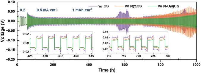 | ||
| Fig. 6 Voltage profiles of symmetric Li|Li cells with the CS, N@CS, and N–O@CS separators at 0.2 and 0.5 mA cm−2, 1 mAh cm−2. | ||
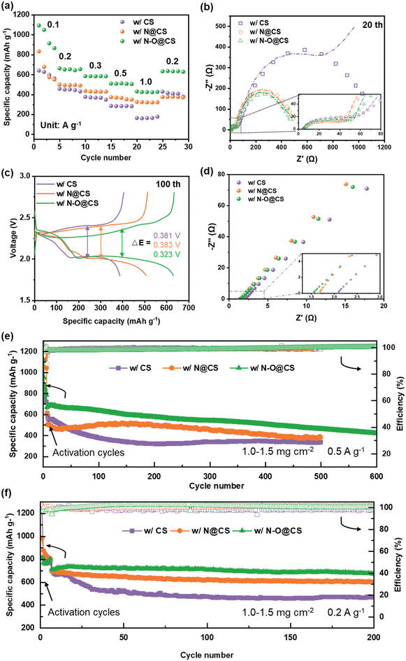
Fig. 7 shows the electrochemical performance of Li–S batteries with different separators. In Fig. 7a, the rate capabilities of the cells are compared. The cell with the N–O@CS separator delivers the highest specific capacities among the three, achieving 1093, 662, 584, 513 and 431 mAh g−1 at current densities of 0.1, 0.2, 0.3, 0.5, and 1.0 A g−1, respectively. When the current returns to 0.2 A g−1, the capacity returns to 632 mAh g−1, equivalent to a capacity retention of 95.6%, indicating excellent rate performance and structural stability.
Fig. 7b and S4 show the Nyquist plots from electrochemical impedance spectroscopy (EIS). The Li–S cell with a CS separator exhibits a continuous increase in impedance over 0, 10, and 20 cycles, indicating interfacial degradation. In comparison, the N@CS separator shows an increase in impedance within the first 10 cycles, followed by stabilization up to 20 cycles. Notably, the cell with the N–O@CS separator displays a significant decrease in impedance after 20 cycles, suggesting improved interfacial compatibility and long-term stability of the separator. Specifically, as shown in Fig. 7b, the solid electrolyte interphase resistances (RSEI), derived from the high-frequency semicircles, are 52.92 Ω (CS), 39.60 Ω (N@CS), and 39.37 Ω (N–O@CS), as summarized in Table S1. In terms of charge transfer resistance (Rct), the Li–S cell with the N–O@CS separator exhibits the lowest Rct value (127.75 Ω) at the 20th cycle, significantly lower than those of the cells with N@CS (453.91 Ω) and CS (967.92 Ω).33,34 These results further confirm that the N–O@CS separator promotes enhanced interfacial stability and faster ion transport. Fig. S5 shows the voltage profiles of Li–S cells assembled with different separators. As illustrated in Fig. S5a, the N–O@CS cell exhibits only a slight increase in polarization over prolonged cycling, in contrast to the more pronounced voltage gap observed in the cells with the CS separator (Fig. S5a) and N@CS separator (Fig. S5b). Furthermore, Fig. 7c and Table S2 reveal that among the three separators, the N–O@CS separator delivers the smallest midpoint voltage gap (Δ = 0.323 V, 0.5 A g−1) between charge and discharge curves, indicating lower polarization and improved reaction kinetics.
The SS||SS (SS: stainless steel) cells were employed to obtain the ionic conductivities of the modified separators, as shown in Fig. 7d. The ionic conductivity (σ) was calculated using equation:  , where L is the thickness of the separator, A is the area of the stainless-steel electrode, and Rb is the bulk resistance of the separator calculated from the EIS plot. The N@CS and N–O@CS separators exhibit ionic conductivities of 1.01 mS cm−1 and 1.11 mS cm−1, respectively, both higher than that of the CS separator (0.68 mS cm−1). These results highlight the superior ion migration capability of the N–O@CS separator.
The long-term cycling performances are shown in Fig. 7e and f. At a current density of 0.5 A g−1 (Fig. 7e), the Li–S cells with CS and N@CS separators exhibit severe capacity fading, dropping to 332 and 387 mAh g−1 after 500 cycles. In contrast, the N–O@CS cell demonstrates excellent cycling stability, maintaining a capacity of 440 mAh g−1 with a retention of 62.3% after 600 cycles. Furthermore, at a current density of 0.2 A g−1 (Fig. 7f), the N–O@CS-based cell achieves a high capacity of 675.5 mAh g−1 with a retention of 95.3% after 200 cycles, outperforming the cells with CS (468 mAh g−1, 72%) and N@CS (603 mAh g−1, 90.1%). Additionally, the performance of Li–S cells with the N–O@CS separator at elevated sulfur loadings was evaluated, as shown in Fig. S6. The cells with sulfur loadings of 2.1, 3.4, and 5.0 mg cm−2 deliver stable cycling performance, achieving capacity retentions of ∼73.3%, ∼65.0%, and ∼86.7% after 200 cycles, respectively. SEM analysis after long-term cycling (Fig. S7) reveals severe material deposition on the CS separator, while the N@CS and N–O@CS separators maintained intact structures. Correspondingly, the Li anode paired with the CS separator showed a rough surface, whereas those paired with the modified separators remained relatively smooth, confirming their effectiveness. This superior long-term performance can be attributed to the enhanced interfacial stability and polysulfide confinement provided by the N/O-rich functional interlayer.
4. Conclusion
In summary, we successfully fabricated a novel N- and O-rich interlayer on a commercial separator via a facile one-step hydrolysis of PAN to address the polysulfide shuttle effect and uneven lithium deposition in Li–S batteries. The introduction of N- and O-containing functional groups endows the modified separator (N–O@CS) with enhanced electrolyte wettability, mechanical stability, and interfacial regulation, benefiting from N- and O-derived functional groups. EIS, CV, voltage profiles, and cycling performance tests confirm that the N–O@CS separator facilitates lithium-ion transport and improves cycling stability. As a result, Li–S cells equipped with the N–O@CS separator deliver a capacity of 440 mAh g−1 with a retention of 62.3% after 600 cycles at a current density of 0.5 A g−1. Furthermore, at a current density of 0.2 A g−1, the N–O@CS-based cell achieves a high capacity of 675.5 mAh g−1 with a retention of 95.3% after 200 cycles. This work provides a facile strategy for separator engineering toward high-performance Li–S batteries.Author contributions
Ying Guo: writing – original draft, experimental design, investigation, conceptualization and formal analysis. Justin Zhong: investigation. Jin Liu: writing – review & editing, supervision, funding acquisition. Wei-Hong Zhong: writing – review & editing, supervision, funding acquisition.Conflicts of interest
The authors declare that they have no known competing financial interests or personal relationships that could have appeared to influence the work reported in this paper.Data availability
Supplementary information: it includes data-processing details from the main text and additional experimental characterizations, such as tensile stress–strain, TGA, UV-vis, electrochemical, and SEM data. See DOI: https://doi.org/10.1039/D5LF00211GAll data supporting the findings of this study are available within the article and its SI.
Acknowledgements
This work was supported by USDA NIFA 2022-67021-38685. The authors would like to gratefully acknowledge the support on microscopy characterization from the Franceschi Microscopy & Imaging Center at Washington State University.References
- Y. Fei and G. Li, Adv. Funct. Mater., 2024, 34, 2312550 CrossRef CAS.
- Y. Chen, Y. Liao, Y. Qing, Y. Ding, Y. Wu, L. Li, S. Luo and Y. Wu, J. Energy Storage, 2024, 99, 113186 CrossRef.
- Z. Wang, Y. Li, H. Ji, J. Zhou, T. Qian and C. Yan, Adv. Mater., 2022, 34, 2203699 CrossRef CAS PubMed.
- L. Zhou, D. L. Danilov, R.-A. Eichel and P. H. L. Notten, Adv. Energy Mater., 2021, 11, 2001304 CrossRef CAS.
- H. Hong, N. A. R. Che Mohamad, K. Chae, F. Marques Mota and D. H. Kim, J. Mater. Chem. A, 2021, 9, 10012–10038 RSC.
- Y. Guo, C. Ying, L. Ren, J. Zhong, J. Liu and W.-H. Zhong, Adv. Sustainable Syst., 2025, 9, 2400572 CrossRef CAS.
- H. Moon, J.-H. Kim, N. Yao, M.-H. Ryou, X. Chen, Y. Park, S.-P. Han, C. Bak, H. Kang, Y. M. Lee, Y. M. Jung, Q. Zhang and S.-Y. Lee, Adv. Mater., 2025, 37, 2414335 CrossRef CAS PubMed.
- L. Ren, C. Ying, C. Wang, Y. Guo, J. Liu and W.-H. Zhong, J. Energy Storage, 2024, 100, 113547 CrossRef.
- G. Raj Deivendran, S.-H. Wu, Y.-S. Wu, J.-K. Chang, R. Jose, K. H. Ng, M. Poddar, C.-L. Sun and C.-C. Yang, ACS Appl. Energy Mater., 2024, 7, 3321–3338 CrossRef CAS.
- Z. Shi, S. Thomas, D. Guo, Z. Tian, Z. Zhao, Y. Wang, A.-H. Emwas, N. Wehbe, G. Melinte, O. M. Bakr, O. F. Mohammed and H. N. Alshareef, ACS Energy Lett., 2024, 9, 5391–5402 CrossRef CAS.
- J. Zhong, L. Ren, C. Ying, Y. Guo, J. Liu and W.-H. Zhong, J. Energy Storage, 2025, 109, 115251 CrossRef.
- Y. Li, Q. Zeng, I. R. Gentle and D.-W. Wang, J. Mater. Chem. A, 2017, 5, 5460–5465 RSC.
- L. Ren, Y. Guo, C. Ying, J. Tangxin Zhong, J. Liu and W.-H. Katie Zhong, ChemSusChem, 2025, 18, e202402284 CrossRef CAS PubMed.
- Y. Guo, C. Ying, L. Ren, J. Zhong, S. Yu, Q. Zhang, J. Liu and W.-H. Zhong, J. Energy Storage, 2024, 104, 114588 CrossRef.
- L. Ren, Y. Guo, J. Zhong, C. Ying, J. Liu and W.-H. Zhong, Adv. Sustainable Syst., 2025, 9, 2500076 CrossRef CAS.
- C. Tu, Z. Zhang, X. Qi, F. Wang and Z. Yang, Chem. Eng. J., 2024, 499, 155915 CrossRef CAS.
- Z.-J. Shi, Y.-W. Tian, X.-L. Wang, Z.-R. Li, W.-J. Song, Z.-Y. Hu, H. S. H. Mohamed, L.-H. Chen, Y. Li and B.-L. Su, ACS Appl. Mater. Interfaces, 2025, 17, 23948–23958 CrossRef CAS PubMed.
- J. Sun, J.-Y. Hwang, P. Jankowski, L. Xiao, J. S. Sanchez, Z. Xia, S. Lee, A. V. Talyzin, A. Matic, V. Palermo, Y.-K. Sun and M. Agostini, Small, 2021, 17, 2007242 CrossRef CAS PubMed.
- M. Agostini and A. Matic, Small, 2020, 16, 1905585 CrossRef CAS PubMed.
- B. Long, J. Ma, T. Song, L. Liu, X. Wang, S. Song and Y. Tong, Chem. Eng. J., 2021, 414, 128799 CrossRef CAS.
- Y. Wang, K. Zhou, L. Cui, J. Mei, S. Li, L. Li, W. Fan, L. Zhang and T. Liu, J. Power Sources, 2024, 591, 233853 CrossRef CAS.
- Y. Guo, P. Sireesha, C. Wang, L. Ren, C. Ying, J. Liu and W.-H. Zhong, J. Power Sources, 2025, 630, 236145 CrossRef CAS.
- H. Wang, Y. Wang, P. Zheng, Y. Yang, Y. Chen, Y. Cao, Y. Deng and C. Wang, ACS Sustainable Chem. Eng., 2020, 8, 12799–12808 CrossRef CAS.
- H. Guo, T. Sun, Q. Yin, X. Li, Z. Chen and X. Ma, Sustainable Energy Fuels, 2024, 8, 1369–1388 RSC.
- T. Li, D. Zhao, M. Shi, T. Wang, Q. Yin, Y. Li, J. Qi, F. Wei and Y. Sui, J. Mater. Chem. A, 2023, 11, 1461–1472 RSC.
- X. Li, J. Yu, W. Li, Y. Liao, M. Li, B. Zhao, X. Liu, S. Huang, S. Xia, J. Zhang and Y. Jiang, Chem. Eng. J., 2025, 505, 159355 CrossRef CAS.
- Z. Liu, Q. Hu, S. Guo, L. Yu and X. Hu, Adv. Mater., 2021, 33, 2008088 CrossRef CAS PubMed.
- S. Y. Jin, M. H. Kim, Y. G. Jeong, Y. I. Yoon and W. H. Park, Mater. Des., 2017, 124, 69–77 CrossRef CAS.
- Z. Yu, Y. Shao, L. Ma, C. Liu, C. Gu, J. Liu, P. He, M. Li, Z. Nie, Z. Peng and Y. Shao, Adv. Mater., 2022, 34, 2106618 CrossRef CAS PubMed.
- K. Wang, Y. Wang, J. Wang, H. Wang, C. Ding, Z. Zheng, Y. Liu, Z. Luo and Y. Ding, Adv. Funct. Mater., 2025, 35, 2422689 CrossRef CAS.
- F. Ma, K. Srinivas, X. Zhang, Z. Zhang, Y. Wu, D. Liu, W. Zhang, Q. Wu and Y. Chen, Adv. Funct. Mater., 2022, 32, 2206113 CrossRef CAS.
- J. Qian, Y. Xing, Y. Yang, Y. Li, K. Yu, W. Li, T. Zhao, Y. Ye, L. Li, F. Wu and R. Chen, Adv. Mater., 2021, 33, 2100810 CrossRef CAS PubMed.
- J. Yan, X. Liu and B. Li, Adv. Sci., 2016, 3, 1600101 CrossRef PubMed.
- S. Li, C. Li, T. Yang, W. Wang, J. Lu, W. Fan, X. Zhao, X. Zuo, S. Tie and J. Nan, ChemElectroChem, 2021, 8, 745–754 CrossRef CAS.
| This journal is © The Royal Society of Chemistry 2025 |

