
 Open Access Article
 This Open Access Article is licensed under a Creative Commons Attribution-Non Commercial 3.0 Unported Licence
Rock-on-a-chip: a novel method for designing representative microfluidic platforms based on real rock structures and pore network modelling†
Pablo A.
Godoy
 a,
Alirza
Orujov
b,
Aurora
Pérez Gramatges
ac and
Saman A.
Aryana
*bd
a,
Alirza
Orujov
b,
Aurora
Pérez Gramatges
ac and
Saman A.
Aryana
*bd
aChemistry Department – Pontifical Catholic University of Rio de Janeiro (PUC-Rio), Rio de Janeiro, Brazil. E-mail: aurora@puc-rio.br
bDepartment of Chemical Engineering, University of Wyoming, Laramie, USA. E-mail: saryana@uwyo.edu
cLaboratory of Physical-Chemistry of Surfactants (LASURF), Rio de Janeiro, Brazil
dSchool of Energy Resources, University of Wyoming, Laramie, USA
First published on 27th March 2025
Abstract
Microfluidics is a key tool for studying pore-scale phenomena in porous media, with applications in oil recovery and carbon storage. However, accurately replicating rock pore structures in quasi-2D microfluidic platforms remains a challenge. Existing design strategies, including regular and irregular networks, fractal geometries, thin-section imaging, and multi-step methods using CT scans and SEM images, often fail to capture real pore space morphologies. To address these issues, we developed a multi-step workflow that preserves pore morphology and size distributions in quasi-2D microchips (rock-on-a-chip) by generating 2D pore throats from 3D network data of CT-scanned rock samples. The method showed strong agreement between 2D and 3D pore and throat size distributions in both designed patterns and fabricated microchips. A critical factor in achieving accurate pore geometry was precise mask alignment, which enabled the fabrication of microchips with narrower throats for relatively tight reservoir patterns. Permeability regulation was achieved by adjusting inlet areas while maintaining pore and throat size distributions similar to the original 3D subvolume. Flow simulations using the Hagen–Poiseuille equation within the OpenPNM framework showed differences between simulated and experimental permeability, especially in low-permeability designs, which were more sensitive to the etching process. Despite these challenges, the proposed approach minimizes common discrepancies between rock pore space morphologies and quasi-2D microchips, significantly improving the reliability of microfluidic studies for applications requiring accurate pore-scale structures.
Introduction
Microfluidics is a critical area of research for visualizing and understanding fluid flow phenomena in porous media. It also serves as a valuable tool for benchmarking numerical models used in oil recovery and carbon subsurface storage operations.1–4 Microfluidic platforms are often designed using regular and irregular network patterns,5–9 fractal geometries,10 or thin section images.11,12 Additionally, pore space images from computerized tomography (CT) scans and scanning electron microscope (SEM) are used for creating two-dimensional porous media through multi-step methods.13,14Currently available methods for designing microfluidic platforms have certain limitations. Regular and irregular pattern networks fail to represent real pore morphologies because they adopt simplified geometries and fixed pore connectivity.6,9 Fractal patterns require a porosity of at least 50–60% for flow to occur,8,10 which restricts their ability to reproduce tight patterns from different formations. Thin-section methods attempt to reproduce the 3D pore structure of rock samples using 2D thin-section images and usually rely on supplementary experimental data, such as mercury injection capillary pressure (MICP) data, to define connected throats based on throat size distribution (TSD).12,15,16 However, thin-section method may omit critical pore space features due to their reliance on 2D pore data. For example, the pore size distribution (PSD) of a core sample could be inaccurately represented by a single slice acquired in the process.17,18 Also, throats are added manually according to the MICP data, decreasing the efficiency of the method and introducing subjectivity in defining throat morphology. Finally, MICP data is a destructive technique, which prevents the re-use of samples for other analyses, impeding parallel studies of rock-like microfluidics with complementary benchmarking techniques such as coreflooding experiments. In contrast, multi-step approaches, which rely on non-destructive imaging techniques, can generate more realistic 2D representations of porous media.3 Randomly generated 2D networks can incorporate the statistical information from the extracted 3D network,1,19 while other algorithms, such as the QSGS algorithm, generate statistically representative 2D images of rock pore space based on 3D data.13,20 However, these methods only extract statistical information from 3D rock morphology data to generate 2D porous media, overlooking the detailed pore morphology. In foam studies for enhanced oil recovery and geological carbon storage, the pore geometry and topology should be as representative as possible because these characteristics dictate foam texture and stability in microscopic pore systems.21–23
Another aspect often overlooked in the design of microfluidic platforms (microchips), is the regulation of absolute permeability. This property greatly impacts the average fluid velocity inside microchannels, influencing the capillary number, and consequently, all phenomena observed on microfluidic platforms.24 Absolute permeability is primarily determined by pore connectivity and microstructure. However, manipulating these features in an image or pore network model while preserving the overall rock characteristics, is challenging and may require a statistical approach rather than individual pore/throat modifications.25–27 The challenge is even greater for heterogeneous rocks, such as carbonates. Existing carbonate-based microfluidic devices typically feature regular geometries, even in fractured systems, and are often designed as dual-porosity regular networks due to difficulty of reproducing the complexes flow characteristics in a 2D device.28–30
In our multi-step approach, we propose a method for creating 2D representations of rock pore spaces in microchips (rock-on-a-chip) that preserve most of the original pore morphology. An algorithm is developed to create pore throats on a 2D pore mosaic based on 3D network data extracted from a CT-scanned core sample. Additionally, a straightforward approach implemented to attempt for permeability regulation. This is achieved by altering the inlet areas of the designed 2D pattern, which has sufficiently similar PSD and TSD to the 3D subvolume. Flow simulations are performed on the design-extracted networks using the Hagen–Poiseuille equation within the OpenPNM framework.31 The permeability simulations for 2D fabricated microchips designed using the proposed method were validated against experimental data from commercial microchips in the literature. This approach enabled the creation of designs with significantly varied permeabilities while maintaining consistent PSD and TSD. The microchips were fabricated using an in-house photolithography method. They were characterized through flow experiments to determine absolute permeability and through imaging to compare the final morphology with the original design.
Materials and methods
Chemicals and substrates
Four borosilicate chrome and photoresist-coated wafers from TELIC were used as substrates for transferring the pattern onto the glass. A developer (Microposit 351), a chrome etchant (Transene) and a glass etchant (BD etchants/Transene) (Transene) were used during the fabrication process to transfer the pattern. To protect the glass areas not intended for etching, a silylation agent (HDMS) and photoresist resin (SU-08/Microchem) were applied. N-Methyl-2-pyrrolidone (NMP, Ultra Pure Solutions) was used to clean the wafer after etching. Additionally cleaning steps involved Piranha Solution (a mixture of H2SO4 from Sigma-Aldrich and H2O2 from Fisher chemical) and an HCl solution mixed with H2O2 (both from Fisher Chemical). Acetone (Fisher Chemical), ethanol (Decon Laboratories), and deionized (DI) water were used for cascade rinsing of the wafer at specific stages, as described later.Petrophysical characterization of core samples
Two types of outcrop rock analogue to oil reservoirs, Indiana limestone and Berea sandstone, were provided as core samples by Kocurek Inc. The porosity of the cores was measured using an UltraPore®600 helium porosimeter, while permeability was measured using an Ultraperm®610 permeameter with nitrogen gas. Klinkenberg correction was applied to calculate the absolute permeability for each sample. Measured porosity was used as a reference to segment the pore space from CT scanned rock images. Permeability was measured to ensure we were working with samples in the order of millidarcy (mD).Pore space images from rock cores
CT-scan images of both rocks were acquired using a ZEISS Xradia 510 Versa X-ray micro-CT scanner. The final image resolutions were 6 μm per pixel in length and width. The scans were performed at a voltage of 140 kV. Pore space images were segmented in Avizo® software based on experimental porosity values. Longitudinal slices of the pore space volume were also extracted using this software. These slices were combined into a 2D pore mosaic, which was subsequently processed to connect the pores using the proposed method.Proposed multi-step method to generate 2D representative porous media
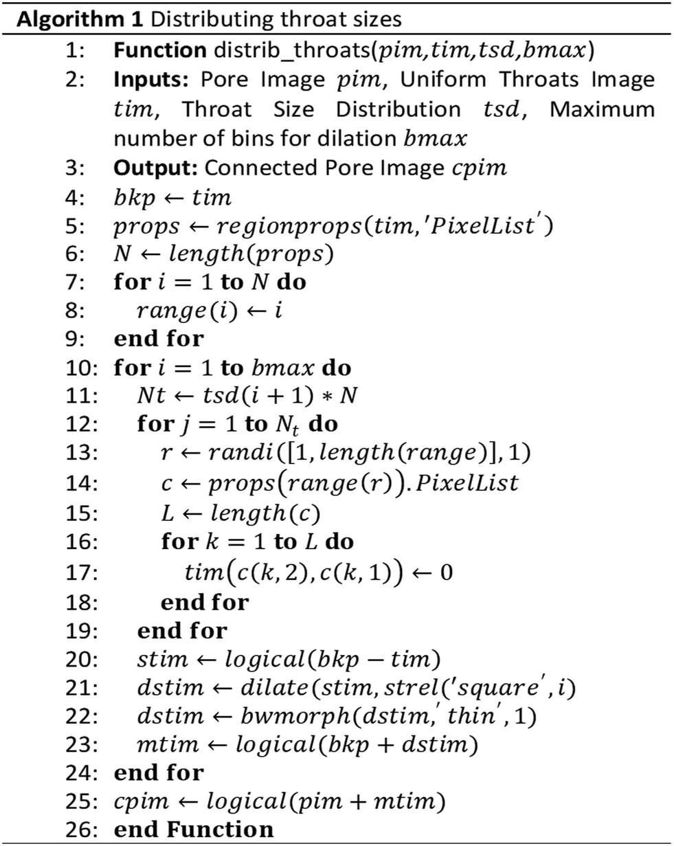
The design method proposed in this work enables the fabrication of a 2D porous medium that closely resembles the original rock pore structure, including its PSD and TSD. Also, it allows for the regulation of theoretical absolute permeability while preserving both the PSD and TSD. The method consists of an initial step to gather data from the segmented pore space, followed by four consecutive steps of image processing (Fig. 1). | ||
| Fig. 1 Proposed steps for rock pattern design method. | ||
Pore mosaic creation based on pore space longitudinal slices
The 3D image obtained from the CT scan was segmented using Avizo® software, with the intensity threshold determined based on the difference between the measured porosity and the calculated porosity (Fig. 2a). A representative subvolume of the pore space for each rock was sliced longitudinally and combined randomly in MATLAB® to create a pore mosaic (Fig. 2b). | ||
| Fig. 2 (a) Pore space segmentation, (b) pore mosaic generation and (c) network data extraction from scanned rocks processes. Both PSD and TSD were normalized by the maximum number of pores or throats. | ||
The mosaic was then filtered to remove artifacts with area smaller than 4 pixels, as they were considered image noise. SNOW algorithm31 was used to extract the pore network PSD and TSD from the 3D volume (Fig. 2c) and the filtered mosaic. Both PSDs were compared to check if they corresponded (Fig. S1, see ESI†).
Throats addition and editing
Based on the representative pore mosaic (Fig. 3a), a parallel image is created by dilating the pores (Fig. 3b), connecting the interfaces and filtering out generated artifacts (Fig. 3c) using MATLAB's bwmorph function. The skeleton of the resulting image is extracted using MATLAB's bwskel function (Fig. 3d) which applies the medial axis transform.32 A parameter, J, is introduced to regulate the dilation intensity (Fig. 3b). In practice J is the number of iterations of the dilation operation, which consequently determines the number of throats in the extracted skeleton. A low value for J results in fewer pores being connected due to insufficient dilation reach. Conversely, a higher J value leads to a saturated image with reduced connectivity in the skeleton, and the throat directions between pores diverge more significantly. | ||
| Fig. 3 (a) Initial pore mosaic, (b) dilated mosaic, (c) connected and filtered dilated mosaic, (d) extracted skeleton, (e) extracted throats, (f) uniformly dilated throats, (g) randomly dilated throats based on subvolume TSD, (h) connected initial mosaic with edited throats and (i) smoothed version of connected mosaic. | ||
The skeleton image is then processed to isolate throats (Fig. 3e). This is achieved by combining the original mosaic and skeleton images and selecting pixels that lie outside the pore area but within the skeleton (i.e., throats). The throats are separated from the skeleton image, and those that are perfectly vertical or horizontal are filtered out, as they do not naturally occur in target rocks structures. The remaining throats are dilated uniformly to a minimum width that allows them to be identified by the SNOW algorithm (Fig. 3f). For both sandstone and carbonate patterns, the throat minimum width is 3 pixels, achieved by applying two dilations to throats that are initially 1 pixel wide.
Most of the previous throats have uniform widths, resulting in a TSD that does not adequately represent larger throats (Fig. S2, ESI†). To create a more representative TSD, a defined portion of throats are randomly dilated at ascending numbers of times to form distinct throat categories. The number of throats randomly selected for dilation in each category is based on the normalized frequency of the rock's TSD for that category, multiplied by the maximum number of throats in the pattern (lines 10 to 24 in the Algorithm 1).
For sandstone the process is repeated for three consecutive dilations (binmax = 3), while for the carbonate pattern, it is repeated five times (binmax = 5), as the latter has larger throats in its subvolume distribution. After a certain number of consecutive dilations, throats become large enough that they are recognized as pores by the SNOW algorithm (Fig. S3, see ESI†), which reduces the PSD representativeness. To mitigate this, a thinning process (bwmorph function) was applied to the throats after each dilation to minimize the addition of extra pore space caused by editing (Fig. S4, see ESI†). This ensures that the introduction of new pores in the PSD is kept at a minimum. Finally, the final edited throats are added to the initial pore mosaic (Fig. 3h) and smoothed by repeating a sequence of dilation, connection, noise filtering, and thinning of the pore space (Fig. 3i).
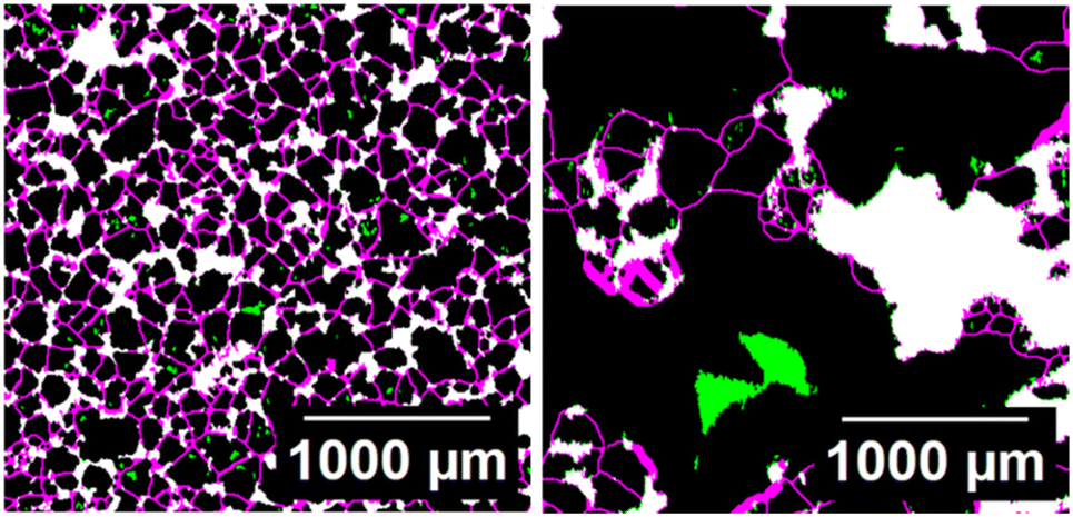
An additional step is included for sparser pore mosaics, such as the limestone pattern. This process includes closing the throats within large grains that would otherwise form small dead-end pores. These pores are harder to access during chip saturation for permeability determination (Fig. 4). This step also eliminates partially connected throats (loose ends).
 | ||
| Fig. 4 Extra process: elimination of partially connected throats (green) and some dead-end pores (also green). White represents the maintained pore space. | ||
The inlet and outlet distribution systems attached to the pattern were designed in accordance with Murray's law (eqn (1)) and a CAD file incorporating the inlet and outlet was generated for photo plotting the UV-masks.
| dparent3 = d13 + d23 | (1) |
Murray's law defines the relationship between the diameter of a parent channel (dparent) and the diameters of its daughter channels (d1 and d2) to ensure minimal energy expenditure for fluid movement.33
Parameter choice based on PSD and TSD
A quantitative criterion was established to choose the optimal J value for the pattern. Each value of J would result in a design with single PSD, TSD and number of grains (ngrains). The maximum mean squared error (MSE) between the design and subvolume size distributions was used as a normalizing factor, as well as the maximum value of ngrains in the design (eqn (2)).This criterion ensures the chosen J value results in a design that has little deviation from the representative volume pore and throat size distributions. Additionally, it ensures the generated design has enough grains to avoid restrictive flow.
 | (2) |
Firstly, the criterion is calculated by computing the MSE for each property (pattern vs. subvolume). Each maximum MSE and ngrains are then computed. The criteria number (CrJ) is then calculated for each J value. The chosen J value must be the one that minimizes the CrJ array.
For the sandstone pattern, J = 11 was chosen, whereas for the limestone pattern, J = 25 was selected. The higher J value for limestone reflects the sparser pore arrangement in its mosaic, requiring greater number of dilations in the initial stage to ensure the pores connect in the subsequent steps.
Pore shape preservation in designed medium
Initial pore mosaic images were combined with the resulting designs utilizing the imfuse MATLAB® function for verifying pore shape preservation. Polydispersity index34 (χ) was introduced to indicate how the overall aspect of the pore size distribution is altered after adding the throats with our algorithm: | (3) |
Permeability regulation on design
To create a design with different permeability, the generated patterns were cropped into narrower images with lower inlet areas. Cropping the image changes the permeability, assuming other variables remain constant, due to the decrease in the cross-sectional area of the medium, as described by Darcy's law, and due to the decrease in pathways from a wider pattern to a narrower one. A specific width was selected so it could fit other patterns on the same substrate. The selected width accounted for our chip holder dimensions, enabling a maximum of 3 patterns in the same chip.Pore networks were extracted using the SNOW algorithm, as incompressible fluid flow was simulated using the OpenPNM python package. The simulation calculates the pressure distribution across the pores in the network and the flow rates in the inlet and outlet throats. The Hagen–Poiseuille flow equation, which assumes spherical pores and cylindrical throats geometries, was used to calculate hydraulic conductivity (g):
 | (4) |
Microchip fabrication
Four microchips (two sandstone-based and two limestone-based) were fabricated using an in-house photolithography method adapted from Hosseini et al.35 with fine adjustments. An extra limestone-based microchip was put to fabrication simultaneously with one of the chips to test reproducibility of the pattern transfer and wettability. The method was chosen based on its ability to produce microchips with complex porous geometries. The process is divided into three main steps: pattern transfer, cleaning, and bonding.A developer solution was applied to transfer the pattern to the photoresist layer. The wafer was then submerged in a chrome etchant, transferring the pattern to the chrome layer. The other faces of the wafer were coated with HDMS, which served as a primer, followed by a coating of the photoresist. This ensured that during the next step, only the glass surfaces exposed to glass etchant could be etched. The wafer was subsequently submerged in a glass etchant solution (BD etchant) in an ultrasonic bath for a sufficient time to achieve a minimum channel depth of 10 μm. The channels depth was characterized by using an Olympus LEXT OLS4000 3D laser microscope after the etching process.
Microchip characterization
Images of the four fabricated chips were taken using a Phase One IQ3 digital camera with an achromatic 60 MP sensor and channel profiles were taken with an Olympus LEXT OLS4000 3D laser microscope (during fabrication). Digital camera was used to gather images with wider field of view for PSD and TSD determination. Laser microscope profile data was used to measure channel depth before bonding substrates with the cover plate. High resolution images were taken with a Leica DM2700M optical microscope for evaluating the degree of morphology preservation from design to microchip. These images were taken for one of the main limestone chips (cropped pattern) and an extra fabricated one (original pattern) because fabrication conditions were exact the same (etchant solution, etching time and temperature). Thus, making both chips more suitable for testing the reproducibility of the pattern transfer and wettability.Images taken with the digital camera were processed in Ilastik software using its pixel classification algorithm to generate a probability image of pores, throats and background. The resulting images were then segmented using Otsu's algorithm36 in ImageJ software. Due to variation in brightness affecting the pixel classification across all the extension of the images, smaller samples were analysed, and their PSD and TSD were determined and averaged through the samples. This approach enhances the precision of the Ilastik algorithm in labelling pixels into pore space and background since training the model require manual assignment of the labels. The designed and actual distributions of pores and throats were compared to confirm the representativeness of the 2D patterns.
To evaluate the transference efficiency of structural aspects from design to the actual microchip, high resolution microscope images were sampled and segmented using the same pixel classification and Otsu's algorithm. Design images were rescaled so it could match the microchip images resolution. Morphological metrics such as 2D Minkowski functionals (area, perimeter and Euler characteristic)37 were calculated along with the aspect ratio of the structure features or grains. The relative error (eqn (5)) between design and actual average morphological properties (![[P with combining macron]](https://www.rsc.org/images/entities/i_char_0050_0304.gif) ) was compared for the two limestone-based chips fabricated in the same conditions.
) was compared for the two limestone-based chips fabricated in the same conditions.
 | (5) |
Wettability of the same two chips was characterized by in situ contact angle measurements.38 High resolution microscopic images of water injection were acquired, and 35 contact angles were manually measured for each chip using ImageJ software as follows: circular shapes were drawn over the meniscus perimeter as a reference; a parallel segment to the channel surface was drawn to meet the tangent line with the meniscus laterals, the angle between these two lines is the contact angle between water and microchip channels surfaces.
Absolute permeability was determined by saturating the chips with DI water and measuring pressure drop at different flow rates (0.01, 0.02, 0.04, 0.06, 0.08 mL min−1). To determine the pressure drop in the porous media, the hydraulic conductance of the inlet and outlet distributions systems was estimated, allowing pressure drop in each bifurcation to be calucalted.39 These values were then subtracted from the total pressure drop across the chip, leaving the remaining pressure drop as the contribution of the actual porous media. By applying the pressure drop (ΔP) and flow rate (Q) values to Darcy's equation (eqn (6)), the absolute permeability (k) of the porous media was calculated:
 | (6) |
Results and discussion
Designed patterns and comparison with previous rock-on-a-chip (ROC) methods
Two mosaics were generated and connected based on sandstone and limestone pore space, and their PSD and TSD distributions were compared to the original subvolume distributions (Fig. 5a and b). Notably, the method successfully approximated the 2D design distributions to the 3D representative subvolume distributions using pore network modelling. | ||
| Fig. 5 Mask designs and PSD/TSD comparison between subvolume and (a) original sandstone pattern and (b) original limestone pattern. | ||
This result advances the current microfluidic designs used for CO2 gas monitoring and sCO2 dynamics studies as the later works have deployed regular and irregular patterns in microfluidic devices to evaluate fluid dynamics in 2D porous media22,40,41 which has no representativeness of the PSD and TSD of a real rock core. Our method also advances current 2D based thin section methods2,42,43 because our throat size data is based on a 3D rock sample and generating 2D porous media patterns with our algorithm is faster than manually adding throats to the image based on MICP throat size data.11
Connectivity and fluid flow in our designs are also assured as the initial pore mosaic is smoothed and connected such as the largest cluster of pore phase pixels remains in the final image (Fig. 5). This feature avoids interruptions in fluid flow due to disconnected pore images in mosaic assemblage, thus the need for modification of the images border.2,44
Furthermore, the number of dead-end pores can be easily regulated in the last part of the method by changing the minimum grain size for throat closing, advancing designs for the study of dead-end pores effects on flow dynamics without changing the effective pore dimensions.44
Another distinguished feature of our design method is that the throats sizes can be automatically edited by changing the input TSD distribution (see Algorithm 1), which generates more representative throat sizes (Fig. 5) than previous methods which do not incorporate such information.45
Previous ROC methods enable statistically accurate PSD and TSD for 2D porous media representations, however, they also generate artificial pore shapes,13,45 which compromise morphological attributes such as 2D Minkowski functionals37 and, especially, pore aspect ratio,46 leading to chips with misrepresented reservoir characteristics. Our comparison results show that pore size polydispersity (eqn (3)) between initial pore mosaic and the resulted design, were respectively χmosaic = 1.23 and χdesign = 1.28 for the sandstone pattern; and χmosaic = 1.49 and χdesign = 1.50 for the limestone pattern. Results indicate the PSDs were minimally broadened due to the applied method generating new pores, thus sufficiently preserving pore shape from 2D slices to final design for both lithologies (Fig. 7).
Finally, our developed design method expands the reach of ROC applications to a wide range of rock types as it simultaneously preserves pore shape (Fig. 7), PSD and TSD (Fig. 10) for homogeneous and heterogeneous pore spaces.
Cropped design microstructure representativeness
Variations of the original masks were also designed by cropping the patterns, thus reducing the inlet area (Fig. 6a and b). For the cropped version of each pattern, the PSD and TSD demonstrated no significant changes (Fig. 6), indicating the representativeness of the rock microstructure was also preserved for a small section of the original pattern. | ||
| Fig. 6 Cropped mask designs and PSD/TSD comparison between original design and (a) cropped sandstone pattern and (b) cropped limestone pattern. | ||
 | ||
| Fig. 7 Fused image of original pores (white) and added connections (magenta) in (left) the sandstone pattern and (right) limestone pattern. Pores in green were excluded from the original mosaic by the algorithm. | ||
Three copies of the pore network were fabricated on each cropped pattern chip. A single width was imposed on the pattern to ensure a reliable fit on the substrate while accommodating the dimensions of the chip holder later used in permeability measurements.
Lastly, the cropped designs enable permeability regulation by altering the original design inlet area (cropping width) without changing its overall microstructure. This alone does not guarantee permeability control as the etching process can have an impact on the pattern transfer, altering the designed flow properties (see last section of Results and discussion). One can also alter flow characteristics, thus its permeability, by changing input throat size distributions on the algorithm.
Actual pattern morphology and properties of the microchips
Images were acquired after the microchip fabrication of two limestone chips (original and cropped) with equal etching exposure time, to allow for comparison with the designed medium (Fig. 8). | ||
| Fig. 8 Superimposed image of rescaled pattern (light color regions) and microscope images (dark contours) from (left) cropped limestone pattern and (right) the extra original limestone pattern, both chips were etched at the same conditions. | ||
Rescaling the designed images to match microscope scale allowed better overlapping and identification of successfully transferred areas. Exceptions were observed at the contours of grains and some of the smallest grains disappeared due to over-etching.
The average errors of the Minkowski functionals and grain aspect ratio were equally low for both chips (Table 1) indicating a sufficient successful transfer. Etching had more impact on the borders as shown in the higher perimeter error compared to area error, as grain surfaces are more affected by the etchant than its interior. Euler characteristic is sensitive to the etching of smaller grains because of over-etching, decreasing the number of connected components on the image, especially for the original design pattern (chip 2) that yields smaller grains in design than the cropped one (chip 1). This is also reflected in the higher standard deviation of the average properties for the chip 2, where regions with larger pores would be less prone to transference errors than regions with smaller ones.
| Chip | Area | Perimeter | Euler number | Aspect ratio |
|---|---|---|---|---|
| Chip 1 | 5.2% ± 0.4% | 13.7% ± 3.8% | 3.3% ± 1.6% | 1.0% ± 1.0% |
| Chip 2 | 6.6% ± 4.7% | 16.5% ± 7.2% | 12.2% ± 4.9% | 3.4% ± 0.6% |
Low aspect ratio errors for both chips also imply a good efficiency in transferring structural features from design to microchips, as it reproduces grain dimensions with little deviations. Chip 1 and chip 2 also presented, respectively, a measured depth of 21.1 μm and 22.2 μm, this result combined with low average error in structural features indicate reproducibility of pattern transfer with the method when etched conditions are the same while fabricating.
With respect to the surface chemistry of microchip channels, all chips were fabricated with the same substrate material (borofloat/borosilicate glass) which consists of nearly 81% silicon dioxide and 13% boric oxide. The predominantly surface species are often silanols, siloxanes, boric oxides and boric hydroxides.47 Specially the hydroxides species are responsible for a water-wet behaviour due to hydrogen bonding, so it is expected that all fabricated chips exhibit a wettability towards water-wet.
Average in situ contact angle measurements for both chips are: 22.9° ± 7.6° for chip 1 and 21.2° ± 5.9° for chip 2. Results indicate both microchip channels are primarily water-wet (Fig. 9a and b) and confirms the reproducibility of the surface properties at the same etching conditions.
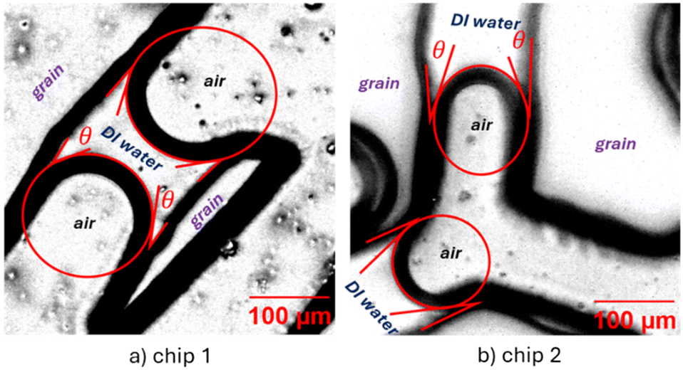 | ||
| Fig. 9 Superimposed image of marked references for contact angle (red) and microscope images during water injection from (a) cropped limestone pattern and (b) the extra original limestone pattern. Contact angles show water-wet behavior. | ||
Regarding the PSD and TSD of the actual microchip patterns for both rock types, three images from each chip were sampled and processed using Ilastik software. The phases were defined as void and background, and a probability image was imported into ImageJ for segmentation by Otsu's method.36 Three out of four chips exhibited PSD and TSD values close to the 3D subvolume (Fig. 10b–d), indicating that the method successfully produced 2D representations of pore dimensions from real rock samples. The original pattern sandstone chip did not represent rock pore throat dimensions (Fig. 10a) as the photomask was aligned with the substrate by tape and not using the support (see discussion of photomask alignment in the next section).
 | ||
| Fig. 10 Pore network of both cropped permeability chips: limestone pattern (left) and sandstone pattern (right). | ||
The extracted pore networks also agree with the original pore structures for each sample (Fig. 11) validating the method's ability to preserve crucial microstructure features. With the PSD and TSD (inscribed radius) of the microchips closely matching those of the subvolume, a high degree of representativeness is achieved without significant sacrifice of pore or throats morphology. The accurate replication of pore geometry and topology information in 2D microchips can greatly enhance the reliability of quasi-2D microfluidic platforms in experimental studies that rely on precise pore-scale behaviour, like foam generation and foam texture ageing.21,22,48–50 It is worth noting that the effectiveness of our approach strongly depends on the characteristics of the initial pore mosaic.
 | ||
| Fig. 11 Pore network of both cropped permeability chips: limestone pattern (left) and sandstone pattern (right). | ||
Although our designs and microchips were based on a 6 μm per pixel resolution CT-scanned mosaic, our method is robust and adaptable across different scales and lithologies, as it performs pixel wise operations. Independence of scale enables the design of nanoscale porous media which play an important role in both sandstone and carbonate rock characterization.51,52 Conversely, the fabrication is limited to photomasks that reproduces 6–7 μm features. Advances in fabrications techniques should be developed to create nanoscale quasi-2D chips with our designs.
Mask alignment to achieve representativeness
We found that the pattern transfer process from the photomask to the glass substrate significantly affects the representativeness of the final microfluidic chip's pore structure. The initial pattern transfer involved cutting the photomask, mounting it onto the substrate surface, securing it with tape at multiple points, and exposing the assembly to collimated UV light. Imperceptible distortions of the thin photomask film led to misalignment and deformation of the projected pattern, as schematically illustrated in Fig. 12a. | ||
| Fig. 12 (a) Encountered pattern distortion issue by holding photomask with tape. (b) CAD image of the newly designed wafer holder. | ||
To address this issue, we designed and 3D-printed a wafer holder (Fig. 12b). The glass substrate fits securely within the plastic mount, while the top lid of the holder is designed to tightly press the photomask against the glass surface using strong magnets and a frame-like structure. This design ensures uniform contact and prevents distortion, significantly improving pattern transfer accuracy before exposure to the UV light.
The improved support enables the fabrication of microchips with PSD and TSD values more closely aligned with those of the sampled rock subvolume, as observed in three of four microchips (Fig. 10). The accuracy of the pattern transfer is enhanced with the support, allowing for the successful transfer of narrower throats to the wafer without creating blockages (Fig. 13). In contrast, improperly transferred or incompletely etched throats can create obstructions in the porous media, restricting fluid flow. If the pore space contains fewer connected pores, the risk of isolating pore areas and disrupting flow pathways increases. A proper alignment provided better definitions of pores and throats in the transferred pattern, ultimately leading to microchips that accurately capture pore morphology and dimensions.
 | ||
| Fig. 13 The resulting patterns from mask alignment with tape (left) and with support (right). Red circles indicate areas that were not transferred due to poor UV incidence on the photoresist layer (distorted mask). | ||
Permeability comparison and effect of etching
Simulated flow rates curves were compared between cropped and original designs (Fig. 14). Cropped patterns appear to have lower slopes indicating lower permeability than original designs. This might be explained by the decrease in parallel pathways by cropping the inlet area maintaining the original length of the medium, channelling flow through a smaller section of the original porous media. The difference in permeability between original and cropped designs from sandstone pattern is lower than the ones derived from limestone pattern because the latter is more heterogeneous. | ||
| Fig. 14 Fluid flow simulations for each designed pattern. | ||
Experimental absolute permeability of the microchips was determined using Pradhan's method.39 However, the experimental values diverged significantly from the simulated values (Table 2). Although the cropped versions are less permeable in simulations, when we consider the actual microchip pore structure and channel depth, the difference between experimental and simulated changes drastically, revealing that cropped versions have significantly higher permeability than original designs. This discrepancy can be attributed to the fact that cropped designs have less pathways, making it sensitive to small changes on its throats size. Some throats become slightly larger during the etching step, since wet etching is mostly an isotropic process, and this increases experimental permeability.
| Microchip | Measured depth (μm) | Simulated k (mD) | Experimental k (mD) |
|---|---|---|---|
| Sandstone original | 11.4 | 530 | 150 |
| Sandstone cropped | 17.1 | 485 | 5001 |
| Limestone original | 16.2 | 232 | 365 |
| Limestone cropped | 21.1 | 114 | 3000 |
Another factor that influenced transport properties was the mask alignment method using tape, which led to throat blockages. This issue was particularly evident in the original sandstone pattern, where the experimental permeability was lower than the simulated values. It is worth noting that the permeability values of the microchips based on the original designs were consistent with the order of magnitude observed in core samples (225 mD for the sandstone and 194 mD for the limestone core). However, the cropped versions exhibited significantly higher values (above 1000 mD).
To test the hypothesis that slightly increases to throat dramatically increases permeability, especially in cropped designs, the design patterns were modified by thinning the grains a few pixels, then fluid flow was re-simulated (Fig. 13).
The designed permeability was highly sensitive to grain etching, particularly for heterogeneous cropped patterns (Fig. 15 top). This finding suggests that, to control permeability outcomes in microchips, it may be necessary to anticipate the etching modifications of the design and control its depth (Fig. 15 bottom). A close match with experimental data was found when the pattern was virtually etched by 2 pixels (roughly 12 μm), demonstrating a permeability 33 times higher than the one previously simulated in design (Kmodified/Kprevious), and supporting the hypothesis of etching effects on fluid flow properties.
 | ||
| Fig. 15 Designed permeability gain because of virtual etching (top) and comparison with experimental curve for cropped limestone pattern (bottom). The slope of both lines is equal to permeability in m2. | ||
Nevertheless, anticipating etching effects in practice can be challenging, as controlling the wet-etching process is complex and does not guarantee to follow the virtual etching simulation. The etching rate depends on precise temperature control and may vary with time. Also, etchant concentration may vary due to uneven distribution across the substrate while in the ultrasonic bath.
Despite the inability to perfectly match simulated and experimental permeability values, this does not invalidate the proposed regulation approach which preserves 2D pore dimensions. The difference in measured permeability between the original and cropped microchips remains significant after fabrication, even though simulations didn't display that magnitude of difference prior. Variations in channel depth can also be associated with unmatching flow properties because uniform depth is not considered in the pore network simulations. To achieve an optimum etching depth that simultaneously preserves pore dimensions and low permeability, direct numerical simulations should be used as an alternative to network simulation.
Finally, to regulate the permeability of the fabricated microchip, a cropped pattern must be designed, as its pathways are more sensitive to grain etching, which will result in a higher permeability than its original version.
Conclusions
The proposed multi-step method followed a standard ROC workflow to transfer the characteristics of 3D porous media to a 2D representation of their pore space. The main findings are summarized as follows:- The proposed method successfully achieved a representative 2D design based on a 3D subvolume acquired from rock core samples, without compromising the real pore morphology. Thousands of pores within the mosaics were successfully and efficiently connected, and the corresponding throat dimensions were transferred to the 2D pattern, ensuring close resemblance to the subvolumes.
- The fabricated microchip's porous media exhibited minor defects; however, the overall morphology was effectively transferred. Comparisons of PSD and TSD between the fabricated microchips and the subvolume data confirmed that the method can achieve representativeness of the 2D microstructure.
- Proper mask alignment plays a critical role in accurately replicating the designed features. Inadequate alignment can lead to throat blockages on the fabricated chip, underscoring the importance of proper fabrication processes.
- The etching process tends to dissolve the grains borders, resulting in an increase in the permeability of the fabricated microchips compared to the original design. Nevertheless, permeability can be regulated during the design phase by adjusting the inlet/outlet area for regions with similar PSD and TSD values.
- Pore network modelling and morphology metrics are essential tools for gathering microstructural information and testing the representativeness of the microchip pore space. It can be rapidly deployed within the ROC workflow to design representative microfluidic platforms using the proposed method.
Data availability
Data presented in the figures may be accessed at: https://doi.org/10.15786/4D6MK3.Author contributions
Conceptualization: A. P. G., S. A. A.; funding acquisition: A. P. G., S. A. A.; methodology: P. A. G., A. O., S. A. A.; resources: A. P. G., S. A. A.; software: P. A. G.; investigation: P. A. G.; visualization: P. A. G., A. O.; supervision: A. P. G., S. A. A.; writing – original draft: P. A. G., A. O.; writing – review & editing: A. P. G., S. A. A.Conflicts of interest
The authors declare no conflict of interest.Acknowledgements
P. A. G. thanks Conselho Nacional de Desenvolvimento Científico e Tecnológico (CNPq) for academic scholarship as well as Coordenação de Aperfeiçoamento de Pessoal de Nível Superior (CAPES-Brazil) for the exchange program scholarship through the Programa Institucional de Internacionalização (PrInt, CAPES/PRINT 88887.937146/2024-00). A. P. G. is thankful for financial support from FAPERJ (E-26/204.241/2024) and for partial support from Coordenação de Aperfeicoamento de Pessoal de Nivel Superior (CAPES-Brazil) – Finance Code 001, and from Shell Brasil through the R&D No. 23016-9 at PUC-Rio and the strategic importance of the support given by ANP through the R&D levy regulation. P. A. G. thanks Francisco José, Marcos Henrique and Prof. Sidnei Paciornik from Laboratório de Microscopia Digital (PUC-Rio) for acquiring and processing CT-scan images. S. A. A. gratefully acknowledges support from the School of Energy Resources at the University of Wyoming.Notes and references
- N. S. Kumar Gunda, B. Bera, N. K. Karadimitriou, S. K. Mitra and S. M. Hassanizadeh, Lab Chip, 2011, 11, 3785–3792, 10.1039/C1LC20556K.
- L. Zuo, C. Zhang, R. W. Falta and S. M. Benson, Adv. Water Resour., 2013, 53, 188–197, DOI:10.1016/j.advwatres.2012.11.004.
- A. Massimiani, F. Panini, S. L. Marasso, M. Cocuzza, M. Quaglio, C. F. Pirri, F. Verga and D. Viberti, Water, 2023, 15, 1222, DOI:10.3390/w15061222.
- M. Sohrabi, A. Danesh and M. Jamiolahmady, Transp. Porous Media, 2008, 74, 239–257, DOI:10.1007/s11242-007-9193-5.
- S. Heidari, M. Ahmadi, F. Esmaeilzadeh and D. Mowla, J. Pet. Explor. Prod. Technol., 2019, 9, 2309–2317, DOI:10.1007/s13202-019-0627-8.
- B. Abedi, M. H. Ghazanfari and R. Kharrat, Energy Explor. Exploit., 2012, 30, 689–705, DOI:10.1260/0144-5987.30.5.689.
- F. J. Meigel, T. Darwent, L. Bastin, L. Goehring and K. Alim, Nat. Commun., 2022, 13, 5885, DOI:10.1038/s41467-022-33485-5.
- N. K. Karadimitriou and S. M. Hassanizadeh, Vadose Zone J., 2012, 11 DOI:10.2136/vzj2011.0072.
- M. Wu, F. Xiao, R. M. Johnson-Paben, S. T. Retterer, X. Yin and K. B. Neeves, Lab Chip, 2012, 12, 253–261, 10.1039/C1LC20838A.
- X. Cheng and L. Jay Guo, Microelectron. Eng., 2004, 71, 288–293, DOI:10.1016/j.mee.2004.01.042.
- F. Guo and S. Aryana, Fuel, 2016, 186, 430–442, DOI:10.1016/j.fuel.2016.08.058.
- M. Buchgraber, M. Al-Dossary, C. M. Ross and A. R. Kovscek, J. Pet. Sci. Eng., 2012, 86–87, 27–38, DOI:10.1016/j.petrol.2012.03.012.
- W. Lei, T. Liu, C. Xie, H. Yang, T. Wu and M. Wang, Energy Sci. Eng., 2020, 8, 986–998, DOI:10.1002/ese3.563.
- M. L. Porter, J. Jiménez-Martínez, R. Martinez, Q. McCulloch, J. W. Carey and H. S. Viswanathan, Lab Chip, 2015, 15, 4044–4053, 10.1039/C5LC00704F.
- F. Guo and S. A. Aryana, in Advances in Petroleum Engineering and Petroleum Geochemistry, ed. S. Banerjee, R. Barati and S. Patil, Springer International Publishing, Cham, 2019, pp. 65–67, DOI:10.1007/978-3-030-01578-7.
- M. Alaskar, K. Li and R. Horne, Stanford Geothermal Workshop, 2013 Search PubMed.
- Y. Liu, C. Guo, J. Cao, Z. Cheng, X. Ding, L. Lv, F. Li and M. Gong, J. Pet. Sci. Eng., 2020, 195, 107921, DOI:10.1016/j.petrol.2020.107921.
- J. M. Bendle, A. P. Palmer and S. J. Carr, Quat. Sci. Rev., 2015, 114, 61–77, DOI:10.1016/j.quascirev.2015.02.008.
- N. A. Idowu and M. J. Blunt, Transp. Porous Media, 2010, 83, 151–169, DOI:10.1007/s11242-009-9468-0.
- M. Wang, J. Wang, N. Pan and S. Chen, Phys. Rev. E: Stat., Nonlinear, Soft Matter Phys., 2007, 75, 036702, DOI:10.1103/PhysRevE.75.036702.
- W. Yu and M. Y. Kanj, J. Pet. Sci. Eng., 2022, 208, 109698, DOI:10.1016/j.petrol.2021.109698.
- W. Yu, X. Zhou and M. Y. Kanj, Langmuir, 2022, 38, 2895–2905, DOI:10.1021/acs.langmuir.1c03301.
- G. J. Hirasaki and J. B. Lawson, SPEJ, Soc. Pet. Eng. J., 1985, 25, 176–190, DOI:10.2118/12129-PA.
- F. Guo and S. A. Aryana, Energies, 2019, 12, 1390, DOI:10.3390/en12071390.
- P. A. Lock, X. Jing, R. W. Zimmerman and E. M. Schlueter, J. Appl. Phys., 2002, 92, 6311–6319, DOI:10.1063/1.1516271.
- D. Coelho, J.-F. Thovert and P. M. Adler, Phys. Rev. E, 1997, 55, 1959–1978, DOI:10.1103/PhysRevE.55.1959.
- P. Spanne, J. F. Thovert, C. J. Jacquin, W. B. Lindquist, K. W. Jones and P. M. Adler, Phys. Rev. Lett., 1994, 73, 2001–2004, DOI:10.1103/PhysRevLett.73.2001.
- F. G. Wolf, D. N. Siebert, M. N. P. Carreño, A. T. Lopes, A. M. Zabot and R. Surmas, Lab Chip, 2022, 22, 4680–4692, 10.1039/D2LC00445C.
- M. H. G. Duits, D. Le-Anh, S. C. Ayirala, M. B. Alotaibi, H. Gardeniers, A. A. AlYousef and F. Mugele, in Day 1 Sun, February 19, 2023, SPE, Manama, Bahrain, 2023, p. D011S038R001 Search PubMed.
- Q. Lv, R. Zheng, T. Zhou, X. Guo, W. Wang, J. Li and Z. Liu, Fuel, 2022, 330, 125533, DOI:10.1016/j.fuel.2022.125533.
- J. T. Gostick, Phys. Rev. E, 2017, 96, 023307, DOI:10.1103/PhysRevE.96.023307.
- H. I. Choi and C. Y. Han, in Handbook of Computer Aided Geometric Design, Elsevier, 2002, pp. 451–471 Search PubMed.
- C. D. Murray, Proc. Natl. Acad. Sci. U. S. A., 1926, 12, 207–214, DOI:10.1073/pnas.12.3.207.
- R. G. Jones, Polym. Int., 2010, 59, 22–22, DOI:10.1002/pi.2749.
- H. Hosseini, F. Guo, R. Barati Ghahfarokhi and S. A. Aryana, J. Visualized Exp., 2020, 61369, DOI:10.3791/61369-v.
- N. Otsu, IEEE Trans. Syst. Man Cybern.: Syst., 1979, 9, 62–66, DOI:10.1109/TSMC.1979.4310076.
- R. T. Armstrong, J. E. McClure, V. Robins, Z. Liu, C. H. Arns, S. Schlüter and S. Berg, Transp. Porous Media, 2019, 130, 305–335, DOI:10.1007/s11242-018-1201-4.
- R. Hu, J. Wan, Y. Kim and T. K. Tokunaga, Water Resour. Res., 2017, 53, 6377–6394, DOI:10.1002/2017WR020721.
- S. Pradhan, I. Shaik, R. Lagraauw and P. Bikkina, MethodsX, 2019, 6, 704–713, DOI:10.1016/j.mex.2019.03.025.
- S. Morais, N. Liu, A. Diouf, D. Bernard, C. Lecoutre, Y. Garrabos and S. Marre, Lab Chip, 2016, 16, 3493–3502, 10.1039/c6lc00830e.
- F. Kazemifar, G. Blois, D. C. Kyritsis and K. T. Christensen, Adv. Water Resour., 2016, 95, 352–368, DOI:10.1016/j.advwatres.2015.05.011.
- M. Buchgraber, T. Clemens, L. M. Castanier and A. R. Kovscek, SPE Reservoir Eval. Eng., 2011, 14, 269–280, DOI:10.2118/122400-PA.
- A. Massimiani, F. Panini, S. L. Marasso, N. Vasile, M. Quaglio, C. Coti, D. Barbieri, F. Verga, C. F. Pirri and D. Viberti, Micromachines, 2023, 14, 308, DOI:10.3390/mi14020308.
- A. D. Bordoloi, D. Scheidweiler, M. Dentz, M. Bouabdellaoui, M. Abbarchi and P. De Anna, Nat. Commun., 2022, 13, 3820, DOI:10.1038/s41467-022-31552-5.
- C. L. Gaol, J. Wegner and L. Ganzer, Lab Chip, 2020, 20, 2197–2208, 10.1039/D0LC00257G.
- J. Ma, L. Liang, M. F. AI-Hamad, M. Van Steene, S. M. Ma and W. Abdallah, in Day 2 Tue, February 13, 2024, IPTC, Dhahran, Saudi Arabia, 2024, p. D021S050R007 Search PubMed.
- Silanes and other coupling agents, ed. K. L. Mittal, VSP, Leiden, 2009 Search PubMed.
- S. A. Jones, N. Getrouw and S. Vincent-Bonnieu, Soft Matter, 2018, 14, 3490–3496, 10.1039/C7SM01903C.
- J. M. F. Façanha, L. F. Lopes, G. Fritis, P. Godoy, R. Weber Dos Santos, G. Chapiro and A. Perez-Gramatges, J. Pet. Sci. Eng., 2022, 218, 111006, DOI:10.1016/j.petrol.2022.111006.
- A. Skauge, J. Solbakken, P. A. Ormehaug and M. G. Aarra, Transp. Porous Media, 2020, 131, 5–21, DOI:10.1007/s11242-019-01250-w.
- B. Bera, S. K. Mitra and D. Vick, Micron, 2011, 42, 412–418, DOI:10.1016/j.micron.2010.12.002.
- B. Bera, N. S. K. Gunda, S. K. Mitra and D. Vick, Microsc. Microanal., 2012, 18, 171–178, DOI:10.1017/S1431927611012505.
Footnote |
| † Electronic supplementary information (ESI) available. See DOI: https://doi.org/10.1039/d5lc00119f |
| This journal is © The Royal Society of Chemistry 2025 |