
 Open Access Article
 This Open Access Article is licensed under a Creative Commons Attribution-Non Commercial 3.0 Unported Licence
Deciphering the unique inertial focusing behavior of sperm cells
Mohammad Moein
Naderi
 a,
Hua
Gao
a,
Jian
Zhou
abc,
Ian
Papautsky†
*a and
Zhangli
Peng†
*a
a,
Hua
Gao
a,
Jian
Zhou
abc,
Ian
Papautsky†
*a and
Zhangli
Peng†
*a
aDepartment of Biomedical Engineering, University of Illinois Chicago, Chicago, IL 60607, USA. E-mail: papauts@uic.edu; zhpeng@uic.edu
bDepartment of Cardiovascular and Thoracic Surgery, Rush University Medical Center, Chicago, IL 60612, USA
cDepartment of Anatomy and Cell Biology, Rush University Medical Center, Chicago, IL 60612, USA
First published on 14th May 2025
Abstract
Inertial focusing has been utilized to advance assisted reproductive technologies (ART) for animal breeding and in vitro fertilization (IVF) by separating sperm cells from biofluids with complex cell backgrounds. While existing studies have aimed to design and optimize sperm separation devices, the fundamental mechanism behind the unique focusing behavior of sperm in spiral channels remains largely unknown: sperm cells focus near the outer wall, whereas most other cells focus near the inner wall. This is primarily due to the lack of a direct modelling scheme for capturing the detailed inertial migration of sperm cells in the spiral channels. In this work, we developed a 3D DNS-PT modeling approach that can predict the inertial focusing of sperm cells with long tails. Unlike previous studies that considered rotating spheres, the novelty of our approach is in extracting the inertial lift force for a triaxial ellipsoid (which represents the asymmetric oval-shaped sperm head) and accounting for the tail effect through appropriate boundary conditions, thus capturing their cumulative impact on sperm focusing behavior. Furthermore, we conducted inertial microfluidics experiments with fluorescent images of spermatozoa to validate the modelling results. We discovered that the effect of the tail, rather than the sperm head shape or orientation, is the primary determinant of the unique inertial focusing position of sperm cells in microchannels. The modelling results provided significant insights into the evolution of particle distribution in the channel cross-section along the flow direction, which was previously unknown due to the limitations of imaging techniques. The predicted particle trajectories enabled detailed analysis and explanation of the distinct migration paths of sperm cells and spherical particles. This work bridges the gap in our understanding of the inertial migration of sperm and other flagellated cells, facilitating the better design and optimization of sorting and separation devices.
1. Introduction
Inertial focusing is one of the most effective microscale particle manipulation tools.1,2 It involves the precise positioning of particles or cells in a channel flow using inertial forces (FL) and covers a wide range of applications, including flow cytometry,3,4 mixing,5 and separation.6–8 Inertia is present in flows with finite Reynolds number (Re = ρUDH/μ, where ρ is the fluid density, U is the average flow velocity, DH is the hydraulic diameter of the channel, and μ is the fluid viscosity). Numerous studies have explored the fundamentals of inertial focusing and the hydrodynamic forces involved in the cross-streamline migration of cells in such devices.9–13 Generally, the most dominant inertial lift forces are the wall-induced force (FW) and the shear-gradient force (FS). The balance of these two forces results in stable focusing (equilibrium) positions in the cross-section of the channel.10 Although these forces are present in the channel irrespective of the particle type or the carrying medium, they can be modified, or new forces may be added based on the fluid or the particle type used. For example, additional deformability-induced lift force can influence deformable cells,14 and manipulating fluid viscoelastic properties may give rise to elasticity-induced lift force (FE).15,16 Moreover, adding curvature to the channel generates counter-rotating vortices (i.e., Dean flow17), orthogonal to the main flow direction, altering the focusing positions due to the additional Dean drag force (FD).18 The Dean flow magnitude is quantified by the non-dimensional Dean number (De = (DH/2R)1/2Re, where R is the radius of curvature of the channel, DH is the hydraulic diameter of the cross-section, and Re is the Reynolds number). Despite serpentine and helical channels offering viable alternatives, spiral devices are the most widely adopted curved geometry for inertial focusing.19 Spiral channels have been successfully used in various applications, including sorting blood cells20 and isolating circulating tumour cells (CTCs) from blood.21In addition to the liquid biopsy and cell biology applications, inertial focusing has been recently applied to reproductive health, including animal andrology,22 human fertility evaluation,23,24 and artificial insemination.25 Reproductive management in pig production benefits significantly from preselecting offspring sex, enabling strategic mating planning based on economic feasibility and technical practicality.26 This trend mirrors the international growth of sexed semen use, with bovine semen currently being sex sorted in approximately 15 countries worldwide.27 Separating sperm cells from a complex cell background is an essential first step in these assisted reproductive technologies (ART).24,28 Over the past decade, successful attempts have been made to take advantage of inertial focusing in spiral channels to separate sperm cells from red blood cells (RBCs),29,30 white blood cells (WBCs),31–33 or both.34 The main principle used in achieving the separation is that in spiral channels, sperm cells uniquely focus near the outer wall, while RBCs and WBCs focus near the inner wall. This enables collecting of cells from separate outlets, based on their final equilibrium position.
Although the main purpose of these investigations has been to design and optimize sperm separation devices, some attempts have been made to propose mechanisms that govern sperm cell dynamics in inertial flow. Numerical and analytical modelling has been an integral part of these investigations, as proposed channel geometries were designed based on these models. However, the design process mostly relied on the assumption that sperm cells behave like 3–5 μm spherical particles,30,31,34,35 disregarding the impact of the irregular sperm head shape or the tail on the inertial migration. To achieve optimal channel dimensions and flow rate for separation, most of these studies applied the lift force model proposed by Ho and Leal, which was originally developed for rigid spheres in two-dimensional Poiseuille flow.36
While these simplifications aid in predicting the focusing quality of sperm cells, they do not accurately predict their focusing position. For instance, Son et al.29 achieved the separation of sperm cells from RBCs in a spiral channel but highlighted that using 5 μm spherical particles to model sperm cells was a challenge due to the irregular shape of sperm cells. They emphasized that the development of a more extensive model for sperm would be valuable to achieve better focusing. Nepal et al.34 showed that 3 μm spheres offered a better model of sperm cell focusing, although they do not focus in the same location as sperm. They optimized a spiral channel geometry to separate sperm cells from WBCs and RBCs, highlighting that the actual sperm focusing position is the symmetric image of the 3 μm beads (near the outer wall instead of the inner wall). In a follow-up study, Son et al.35 used 2D models to study the alignment of sperm-like particles in curved microfluidic channels. They observed that the tail prevents the rotation of the particle significantly and concluded that the sperm cells should be treated as 3 μm spheres instead of the previous assumption of 5 μm. However, a 2D model cannot capture the Dean flow dynamics and its impact on sperm migration, leading to an incomplete understanding of the underlying focusing mechanisms.
Despite the experimental efforts, the absence of a direct modelling scheme hinders a thorough understanding of the mechanisms governing the inertial migration of sperm cells. In this work, we demonstrate and validate a 3D simulation technique capable of predicting the inertial focusing of sperm cells. The novelty of our modelling approach is that it incorporates the effects of both the sperm head shape and the sperm tail into the hydrodynamic lift forces and enables us to dissect their individual contributions to the unique focusing behavior of sperm. Additionally, top-view fluorescent imaging yields an understanding of the evolution of focused streams in both straight and spiral channels. The corresponding simulated particle trajectories are used to fully resolve the migration path of sperm cells in the cross-section of the channel through a side-by-side comparison with spherical particles. Specifically, our numerical and experimental findings underscore the pivotal role of the sperm tail in focusing of sperm cells near the outer wall of the spiral channel. Additionally, they reveal how the sperm head's asymmetric shape and alignment, along with the variation in its size within a sample, influence focusing quality. These insights explain the limitations of existing analytical models in explaining the unique focusing behavior of sperm cells. We hope that this work enhances the knowledge of the dynamics of inertial migration of sperm and other flagellated cells and facilitates the more accurate design of focusing and separation devices.
2. Materials and methods
2.1 The DNS-PT modelling approach
We used a 3-step modelling scheme to simulate the particle trajectories in the channel (Fig. 1). In the first step, the inertial lift force field was obtained using direct numerical simulation (DNS). In the second step, the flow field in the entire channel was resolved, and the drag forces, both perpendicular and orthogonal to the flow direction, were obtained. Finally, in the third step, the inertial lift force from step 1, and the drag forces from step 2 were combined to update the particle positions inside the channel. Since the inertial lift force is calculated using the DNS method, and a particle tracing algorithm is used to simulate particle trajectories, we refer to it as the DNS-PT approach. COMSOL Multiphysics 6.1® (COMSOL, Inc., Stockholm, Sweden) was used to implement all the modelling steps through finite element method (FEM). MATLAB® (The MathWorks, Inc., Natick, Massachusetts, USA) was used for data analysis. Particle distributions were plotted based on the accumulated Gaussian distribution of all particles. The focusing position is the peak of the particle distribution plot.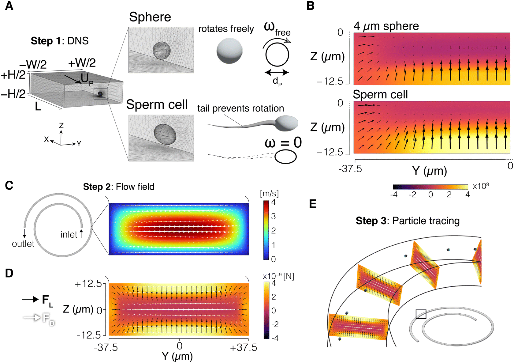 | ||
| Fig. 1 DNS-PT modelling approach. (A) Direct numerical simulation (DNS) simulation box; straight channel segment with periodic boundary condition used to calculate the inertial lift force field. The particle was simulated as a rotating sphere (ωfree) or as an ellipsoid with dimensions of 9 μm × 3 μm × 5 μm (sperm head) with artificially disabled rotation, ω = 0 (tail effect). (B) Lift force field results for the 4 μm sphere and the sperm cell in a quarter of the cross-section; heatmap shows magnitude of the Z component of the lift force. (C) Dean velocity field obtained from solving the flow field in the entire spiral geometry. (D) Lift force field (from step 1) and the Dean drag force (from step 2) were superposed to generate the total force field. (E) Particle tracing step: FL and FD fields were projected orthogonally along the spiral. Particles' positions were updated based on Newton's second law to obtain particle trajectories. | ||
2.2 Direct numerical simulation (DNS) setup
The DNS method was used to capture the interaction between the fluid and the particle and obtain the inertial lift force field. A segment of the channel with cross-section dimensions W (width) × H (height) was simulated with a periodic boundary condition (PBC) at the flow inlet and outlet. The channel length was set to L = 10dP where dP is the particle diameter. The particle was represented as a stationary void in the domain with channel walls moving backward at the inferred particle velocity UP (Fig. 1A). This void takes the shape of a sphere for spherical particles, and a 9 μm × 3 μm × 5 μm triaxial ellipsoid for the sperm cell. These dimensions were selected based on our experimental measurements of the sperm head and those reported in the literature.37,38 The carrying fluid had a density of 1000 kg m−3 and a viscosity of 0.001 Pa s. Varying pressure difference values were used to generate the desired flow rates inside the channel. The Navier–Stokes equations were then solved in the domain, and total stress was integrated on the particle surface to calculate the lift force. Repeating the same process for different particle positions generated the force field in the cross-section of the channel. Note that due to symmetry, only a quarter of the channel was simulated. Details of the DNS approach were reported in our previous work39 and validated by us and others.39–432.3 Sperm tail effect on the particle boundary conditions
We incorporated the effects of the tail on sperm cell dynamics by modulating the boundary condition on the particle surface. In a traditional DNS setting,40 particles are treated as freely rotating spheres in the flow (ωfree). As a result, the linear velocity on the spherical particle surface was set to v = ωfree × r to capture this rotational motion (Fig. 1A), where r is the position vector of the particle surface with respect to its centre. However, as discussed earlier, the sperm tail has proven to prevent the natural rotation of the cell in the flow,35i.e., ω = 0. Therefore, the sperm cell was modelled with manually disabled rotation by adjusting the boundary condition on the particle surface, v = 0 (Fig. 1A). Thus, the impact of sperm head shape on the inertial force field was directly considered, while the effect of the sperm tail was indirectly captured through modulation of the boundary condition. Fig. 1B shows the inertial lift force (FL) field calculated in a quarter of the channel cross-section for a 4 μm sphere and a sperm cell.2.4 Flow field and particle trajectories
Next, the Navier–Stokes equations were solved in the entire channel. Fig. 1C shows the Dean flow generated in the cross-section of the spiral channel. The Dean drag force (FD) was calculated using the Stokes' equation:| FD = 3πμUDdp | (1) |
| mPẍP = FL + FD + Fd | (2) |
2.5 Sperm cell sample preparation
Adult male bovine spermatozoa samples (n = 16) were obtained from Genus PLC (Windsor, WI, USA). The raw samples were received in 10 mL vials and shipped overnight in a temperature-insulated box (ThermoSafe, Inc., Arlington Heights, IL, USA). Received samples were diluted in phosphate-buffered saline (PBS) at pH 7.4 to 2 M cells per mL.For morphological measurements, 10 μL of diluted sample was examined under a bright field on an inverted microscope (Olympus IX83) using 100× objective, and cell dimensions were measured using CellSens software (Olympus America Inc., Waltham, MA, USA).
For flow experiments, to visualize migration trajectories sperm cells were stained with Hoechst 33342 (20 mM; Thermo Scientific, Waltham, MA, USA) following the standard protocol. Vazquez JM et al.46 showed that Hoechst 33342 does not affect the motility or the fertility of spermatozoa.
For experiments involving sperm with tails removed, sperm sample was washed in PBS twice, centrifuged at 300 g (Thermo Fisher Scientific, Inc., Waltham, MA, USA) for 20 min, and sonicated at 25 kHz for 10s using a microtip sonicator47 (Qsonica Sonicator Q500, Fisher Scientific, Inc., Waltham, MA, USA). Trypsin treatment can also be used to efficiently remove the sperm tails.48
2.6 Device fabrication and experimental setup
Microfluidic channels were fabricated in polydimethylsiloxane (PDMS) using the standard soft lithography process with dry photoresist masters, as we detailed previously.15,49 Channel cross-sectional dimensions were fixed at 75 μm in width and 25 μm in height. The spiral channels had 1.5 turns, with an inner radius of curvature of 1 mm. For flow experiments, samples were loaded into a 10 mL syringe with a Luer lock interface. A programmable syringe pump (Legato 201, Kd Scientific, Holliston, MA, USA) was used to flow the sample at 10 to 100 μL min−1. Fluorescence imaging was done using a 20× objective with a high numerical aperture (NA = 0.7) using an inverted microscope (IX83, Olympus America Inc., Waltham, MA, USA) with a 16-bit sCMOS camera (Zyla 5.5, Andor Technology Ltd, Belfast, UK), as we detailed previously.15 To investigate the focusing behavior, solutions of fluorescent 4 μm-diameter polystyrene beads (Polysciences, Inc., Warrington, PA, USA) were prepared with a final volume fraction of 0.03% (v/v), with Tween 80 (Fisher Scientific, Waltham, MA, USA) added at 0.1% (v/v) to minimize aggregation and prevent channel clogging.3. Results and discussion
3.1 Model validation
To validate the modelling approach, the simulation results were compared with experimental observations of the focusing position of 4 μm spherical beads and sperm cells in a 75 μm × 25 μm spiral channel. The spiral has 1.5 turns and an inner radius of 1 mm and the flow direction is inside-out. Fig. 2 shows the lateral focusing position of particles at the channel outlet for a range of average Dean numbers. In the experiments, the 4 μm spherical beads were detected closer to the inner wall (IW) of the channel, which agrees with previous reports for spherical particles.18,21 This observation was compared against the simulation results for a 4 μm sphere using: a) the DNS-PT approach, and b) the COMSOL built-in analytical inertial lift force model. Since COMSOL uses the inertial lift model developed with point-particle assumptions, we added an additional term to the force equations to account for the finite size of the particle.50 The results showed that both modelling techniques predict the focusing of spherical beads near the inner channel wall. Subsequently, the sperm cells were located between the outer wall (OW) and the channel centre, gradually shifting toward the outer wall with increasing De. This focusing behavior agrees well with previous observations.30–32,34 The DNS-PT model captured the focusing of sperm cells near the outer wall in the entire De range. This was a critical observation since we not only validated the ability of our model to closely capture the focusing position of particles but also showed that treating sperm cells as spherical particles leads to inconsistent results (focusing near the inner wall as opposed to the outer wall), irrespective of the modelling technique used. | ||
| Fig. 2 Lateral focusing position of particles in a range of De numbers in the spiral channel. Experimental results for sperm cell and 4 μm spheres are compared against the DNS-PT modelling results, and the COMSOL built-in inertial lift force model. | ||
Next, to further validate the DNS-PT model, sperm cell fluorescent streak velocimetry images for both straight and spiral channels were compared against the simulation results. Fig. 3A and C shows the downstream evolution of focused streams from the top view for flow rates of 10 μL min−1 and 100 μL min−1 (Re = 3.7 and 37, respectively). In the straight channel, sperm cells are focused into two streams near the outlet at Q = 10 μL min−1 (Re = 3.7), equidistant from the channel centre. With increasing flow rate, the streams move towards the channel centre and merge closer to each other. The simulated streams that are presented as heatmaps exhibit trends similar to those observed in the experiments at both flow rates. While fluorescent images assist in a qualitative comparison, line scan data from the experiments are compared against particle distribution plots from the simulations to quantitatively compare the focusing position and stream evolution (Fig. 3B and D). Comparing the exact location of the two streams at 10 μL min−1 (Re = 3.7), the two peaks occur at y = +17.5 μm and −15.5 μm in the experiments, and at y = ±22.6 μm in the simulations. At 100 μL min−1 (Re = 37), the simulated particle distribution closely captures the single wide peak observed at the channel centre.
 | ||
| Fig. 3 Downstream evolution of sperm cell lateral position in a 75 μm × 25 μm straight and spiral channel for Q = 10 μL min−1 and 100 μL min−1 (Re = 3.7 and 37, respectively). (A and C) Top view fluorescent images for sperm cells vs. heatmaps of lateral position of cells in the DNS-PT simulations in the straight, and spiral channels, respectively (B and D) Line-scan data from the experiments (solid line) vs. particle distribution plots from the DNS-PT simulations (dashed line) in the straight, and spiral channels, respectively. | ||
Similarly, two focused streams are formed at Q = 10 μL min−1 (Re = 3.7) in the spiral channel. Simulated heatmaps also predict similar trends, with the gap between the streams distanced slightly wider, precisely at y = +17.5 μm and −15.5 μm in the experiments, and at y = +22.5 μm and −20.5 μm in the simulations. Lastly, the sperm cells were observed to focus into a single stream near the outer wall of the spiral at Q = 100 μL min−1 (Re = 37). The simulations perfectly captured this behavior as well, with the experimentally measured intensity peak at y = +17.5 μm, and the simulation plot reaching its maximum at y = +20.15 μm, resulting in an accuracy of 96.4%. Although slight variations in the exact location and the quality of the focused streams exist between the experimental and simulation results, the DNS-PT model captures the same overall focusing behavior for the sperm cells in both straight and spiral channels.
Lastly, we validated our model against experimental results by Feng et al.30Fig. 4 shows the particle distribution of 3 μm spheres and sperm cells at the outlet of a 200 μm × 50 μm spiral channel at Re = 66.7 (Q = 500 μL min−1). This spiral has 3 turns and an inner radius of 7 mm and the flow direction is inside-out. The solid lines represent experimental results from Feng et al. and the dashed lines are the DNS-PT modelling results. In their experiments, the 3 μm spheres were focused near the inner wall of the channel with the particle intensity peak at y = −56 μm. Our simulations predicted a peak at y = −83 μm, yielding 87% accuracy. On the other hand, sperm cells were collected near the outer wall, with the intensity peak at y = +86 μm. Our model predicted the focusing positions at y = +77 μm, equivalent to an accuracy of 95.5%. However, the sperm focusing quality appears to be lower in the experiments than that observed in the simulations. Note that the experiments by Feng et al.30 were performed using human sperm cells (5 μm × 3 μm × 1.5 μm), while our model is based on bovine sperm cell dimensions (9 μm × 3 μm × 5 μm). These differences in sperm size and morphology between species51 may contribute to the slight variation between the model and experimental results. An additional source of discrepancy could be the heterogeneity of sperm cells in the experiments. As suggested by Son et al.,31 the low focusing quality of sperm can be partly attributed to the asymmetric nature of the sperm cells, which prevents them from behaving like a uniform particle set, while in simulations, sperm cells are treated as a homogeneous particle set, with similar attributes. The impact of heterogeneity of sperm shape and alignment on the focusing position will be discussed in detail below.
 | ||
| Fig. 4 Lateral particle distribution at the channel outlet for sperm cells and 3 μm spheres in a 200 μm × 50 μm spiral channel. Experimental observations by Feng et al. (solid line) vs. DNS-PT modelling results (dashed line). Note that Feng et al. conducted experiments using human sperm cells, while the DNS-PT model is based on bovine sperm cell dimensions. | ||
Collectively, these results validate our modelling approach in predicting the overall focusing behavior of sperm cells in both straight and spiral channels.
3.2 Sperm focusing evolution in the cross-section
Inertial focusing of sperm cells has been studied primarily through top-view fluorescent imaging in the outlet of the channel. In some cases, side-view images were used in straight channels to locate the vertical position of sperm. However, direct observation in the channel cross-section is highly challenging, as particles only appear once in a focal plane.9,52 Thus, details of sperm migration within the channel cross-section are still unclear. Existing theories are merely schematics developed based on coupling top- and side-view images.32,34 To bridge this gap, the DNS-PT model was used to generate cross-section heatmap plots, illustrating the evolution of sperm focusing within the cross-section of the straight and spiral channel (Fig. 5). | ||
| Fig. 5 DNS-PT simulation results of the particle distribution evolution within the cross-section of the 75 μm × 25 μm straight and spiral channels presented as heatmaps for (A) straight channel at Q = 10 and 100 μL min−1 (Re = 10, and Re = 100, respectively) and (B) spiral channel at Q = 10 and 100 μL min−1 (Re = 10, Deave = 0.44 and Re = 100, Deave = 4.4, respectively). | ||
Starting with the straight channel (Fig. 5A), at Q = 10 μL min−1 (Re = 3.7), randomly distributed cells were observed to migrate towards channel corners gradually. This migration seems to occur in two stages. Initially, within the first 3.5 mm downstream, cells are pushed away from the channel walls. Next, lateral and vertical migration away from the centre leads to the four focused streams near the corners. This takes place between 3.5 mm downstream and the channel outlet. Note that the cross-section plots reveal that each of the two streams observed from the top view in the straight channel is, in fact, two pairs of streams stacked vertically on top of each other. Increasing the flow rate to 100 μL min−1 (Re = 37), the inertial migration happens much faster, focusing particles into tighter horizontal bands within the first 3.5 mm. They will then gradually move horizontally, merging into a single wide peak in the centre. Additionally, two focused streams are also observed near the channel side walls. Given the relatively low intensity of the heatmap at these two locations, they may suggest unstable focusing positions.
In the spiral channel (Fig. 5B), the presence of the Dean flow breaks the horizontal symmetry of the focusing positions. Although top-view observations suggest almost identical particle distribution for both straight and spiral channels at Q = 10 μL min−1, Re = 3.7 (Fig. 3A and C), cross-section heatmaps revealed rather different patterns. In particular, the focused streams near the inner wall appeared closer to each other compared to the straight channel at the outlet. This implies that these focused streams near the outer wall are moving inwards vertically under the influence of the Dean drag force. However, the secondary flow is not strong enough for them to fully migrate towards the outer wall following the Dean vortices (Deave = 0.44). On the other hand, the inertial migration takes place much faster at Q = 100 μL min−1 (Re = 37) due to the increased average Dean number (Deave = 4.4). This will allow the streams to move along the Dean vortices all the way towards the outer wall.47 The details of this outward migration will be explained in detail below. Analogous to the case in the straight channel, the focused stream observed from the top view is, in fact, two streams positioned one above the other.
Consequently, confirming the existence of two focused streams for the sperm cells within the cross-section of the channel suggests that further design enhancements are required in applications such as flow cytometry where achieving a single stream is of interest. These design adjustments may include utilizing channels with slanted cross-sections such as trapezoids. Although slanted geometries have been recently used to enhance sperm separation from other non-sperm seminal cells such as leukocytes,33,53 further investigation is required to determine whether similar practice is applicable to achieve single-stream focusing.
3.3 Deciphering migration pathways in the cross-section
The inertial focusing of particles depends on the combined effects of the inertial lift forces (FW and FS). While FW repels particles away from the wall due to the interaction between the particle and the adjacent wall, FS directs them away from the channel centre due to the curvature of the velocity profile.2 Di Carlo et al.40 showed that FW and FS scale with dP6, and dP3, respectively. This often leads to two focusing positions on the vertical centreline of a rectangular channel, near the top and the bottom walls.10,54 In a spiral channel, sperm and spherical particles move in opposite directions due to the Dean flow and equilibrate near the channel's outer and inner side walls, respectively.30Although particles experience the inertial lift forces and the Dean drag force simultaneously as they travel downstream in the channel, the DNS-PT model enables us to isolate the effects of these forces. The main assumption in our model was the impact of the tail on the sperm rotation. As described by Tanzosh and Stone,55 a freely moving rigid sphere does not rotate relative to the fluid, and instead follows the fluid local vorticity. Originally, Cherukat and Mclaughlin56 found that rotation-induced lift force is negligible when particles are far from the channel walls. However, once closer to the walls, the higher shear rate due to the parabolic velocity profile makes the rotation comparable to the shear-gradient force. When the tail halts the sperm's rotation, the local fluid velocity is disturbed. Therefore, the effect of the rotation is no longer negligible compared to the shear-gradient force, as the shear rate in the vicinity of the particle is modified. We confirmed this by probing the shear rate experienced by the particles in the simulations. At approximately halfway between the channel centre and the bottom wall on the vertical centreline, the maximum shear rate experienced by the sperm cell (16.9 × 10⁵ 1/s) was 46% higher than that experienced by the sphere (11.5 × 10⁵ 1/s).
To better understand this effect, we plotted the inertial lift force field on a freely rotating 4 μm sphere and a sperm cell in the 75 μm × 25 μm straight channel at Re = 94 (Fig. 6A and B). Note that only a quarter of the channel was considered due to symmetry. Evidently, although force arrows show similar patterns along the channel walls, the inertial force direction and magnitude in the central regions of the channel exhibit distinctive patterns. Notably, the vertical component of the force (FLZ) which is primarily downwards along the horizontal centreline for the sphere, is smaller in magnitude in the case of sperm cells. Therefore, the vertical equilibria axis of sperm cells shifts towards the channel centre compared to that of the sphere, as shown by the FLZ = 0 dashed lines in the force field plots. The dashed lines are drawn where downward and upward forces meet along the vertical centreline. This is illustrated more clearly in the form of force curve plots along the channel vertical centreline (Fig. 6C). The stable focusing positions in the channel height direction are located where each curve intersects with the FLZ = 0 dashed line with a negative slope. As illustrated, at 3.1 μm away from the centre, the sperm cell's vertical equilibrium position is closer to the centre compared to the sphere, which is marked at 6.4 μm away from the centre.
 | ||
| Fig. 6 Comparison of sperm cells and spherical particles focusing behavior using the DNS-PT simulation results. Inertial lift force field in a quarter of the channel cross-section at Q = 250 μL min−1 (Re = 94) for (A) 4 μm sphere, and (B) sperm cell. Dashed lines represent FLZ = 0 (vertical equilibria axis). Channel centre is the top right corner. (C) Z-Component of inertial force along the channel vertical centreline. Positive (negative) values show centre-directed (wall-directed) forces. The stable focusing position is where curve intersects with the FLZ = 0 dashed line with a negative slope. (D) The migration trajectories of the particles within the channel cross-section. The initial positions are marked by solid circles, and the final position is marked by hollow circles. Arrows show the direction and magnitude of the Dean flow. (E) Particle lateral and vertical distribution plots for the sperm cell and 4 μm spheres. | ||
In the spiral channel, the Dean flow has a central arm toward the outer wall of the channel, and two arms near the top and bottom walls which are toward the channel's inner wall (Fig. 6D). Evidently, the shift of FLZ = 0 for sperm cells toward the centre in the channel height direction makes cells move towards the central arm of the Dean flow, while the original FLZ = 0 position for the spheres is within the inward-bound arms of Dean flow. To better illustrate the concurrent effects of the inertial- and the Dean drag forces on the spherical particles and sperm cells, we plotted the migration paths of individual particles in the cross-section of the spiral channel for four different starting positions (Fig. 6D). The solid circles depict the starting position, and hollow circles show the final stable focusing position. As expected, the vertical migration in the cross-section is predominantly determined by the inertial lift forces, while the direction of the Dean flow governs lateral migration. That is, spherical particles and sperm cells both initially move towards their respective vertical equilibria axis (FLZ = 0 dashed lines), while the Dean flow induces lateral migration toward the final equilibrium positions near either the inner or outer wall. When the particles are released in the corners of the channel (for example top left corner in Fig. 6D), since the vertical component of the Dean flow is relatively significant near the side walls, particles are initially pushed towards the horizontal centreline following the Dean flow. However, as they move away from the channel side wall, their vertical migration is once again mainly governed by the inertial lift force. Therefore, the spherical particle moves back up towards its equilibrium line and focuses near the inner wall, while the sperm cell continuously moves along the equilibrium line towards the outer wall of the channel. Fig. 6E depicts the downstream evolution of particle distribution along the channel width and channel height for the sperm cells and 4 μm spherical particles.
3.4 Dissecting the effects of sperm head shape and sperm tail
As discussed above, the balance of inertial lift near the channel centre is the key factor behind the sperm focusing vertically closer to the centre than spherical particles. Fig. 7A shows the distribution of sperm cells and 4 μm spheres along the channel height at Re = 94. The results confirm a minor shift in the vertical equilibrium position of sperm cells towards the centreline, compared to spherical particles. Our simulation results are consistent with experiments by Feng et al. under similar conditions, where sperm cells were observed to focus closer to the channel centre compared to RBCs at Re = 88.7.30 Feng et al. described how FL tends to focus sperm cells closer to the vertical centre but directs RBCs to near the top and bottom walls, referencing an earlier study where Prohm et al.57 investigated how controlling the rotational motion of particles in 2D Poiseuille flow will impact the inertial lift force profile, and thereby equilibrium positions. | ||
| Fig. 7 Dissecting the effect of the sperm head shape and alignment, and the sperm tail on the inertial focusing behavior. (A) Vertical particle distribution for sperm cells and 4 μm spheres in simulations at Re = 94 vs. experimental observations for RBCs and sperm cells at Re = 88.7 by Feng et al. (B) DNS-PT simulation results of the Z-component of the lift force along half the channel height for a rotating and non-rotating spheres and sperm cell (solid lines); non-dimensional inertial force (fL) measured by Prohm et al. on a 2D circle (dashed lines). (C) Top view fluorescent images at the spiral channel outlet for the 4 μm spheres, sperm cells, and tail-off sperm cells over a range of De numbers. (D) Focusing position of the 4 μm spheres, sperm cells, and tail-off sperm cells at the spiral channel outlet over a range of De numbers. The transparent envelopes show the evolution of the focusing quality in the experiments in terms of the full width at half maximum (FWHM) for each data point. The DNS-PT simulation results (dashed lines) are compared against the experimental observations (solid lines). Please note that due to the limitations of the DNS method, tail-off sperm cells cannot be simulated (due to their rotational asymmetry). | ||
Despite their efforts, it is yet unclear which one of the sperm's unique morphological properties primarily determines the sperm's focusing position. Thus, we attempted to dissect the effects of the sperm head shape, sperm head alignment, and sperm tail on the focusing position. Fig. 7B shows the inertial lift force profile in the Z-direction against the normalized channel height for ease of comparison. The DNS-PT simulation results were plotted for the case of a) a 4 μm sphere rotating freely (ωfree), b) a 4 μm sphere with manually disabled rotation (ω = 0), a sperm cell: 9 μm × 3 μm × 5 μm ellipsoid with manually disabled rotation (ω = 0) in the c) flat-on alignment (5 μm side along the channel width), d) the edge-on alignment (3 μm side along the channel width). The stable focusing positions are located where each curve intersects with the FLZ = 0 dashed line with a negative slope. The force profiles for the rotating and non-rotating spheres match the reported non-dimensional force (fL) data from Prohm et al.57 which was derived for a 2D circular particle.
Comparing unique patterns of the force profiles reveals several key observations. First, the sperm cell experiences increased force values near the channel wall, where FW is the dominant lift force. This is supported by the fact that the alignment of the sperm (both flat-on and edge-on) generated higher pressure on the wall side of the particle due to the larger effective surface of the sperm's largest dimension (9 μm) compared to the sphere (4 μm). This is further verified since the non-rotating spheres experience the same force magnitude near the wall as the rotating sphere. Therefore, rotation does not impact inertial lift magnitude near the channel walls. Second, disabling the particle rotation (tail effect) modifies the force profile near the channel centre, where FS is the dominant lift force. This is irrespective of the particle shape since similar behavior is observed for both the 4 μm sphere and the 9 μm × 3 μm × 5 μm ellipsoid (in both alignments). Although slight variations exist in the force profile between flat-on and edge-on alignments, the alignment itself has minimal impact on the focusing position. However, these variations in alignment cause sperm cells with different orientations to experience moderately different forces across the channel width, which can reduce the focusing quality compared to a uniformly aligned particle set, consistent with the proposed hypotheses by Son et al.29,31
To further confirm that the sperm tail is the primary reason behind the distinctive focusing behavior, we removed the tail from the sperm head and performed a series of experiments on tail-off sperm cells within the spiral channel for a range of Dean numbers. Comparing the focusing position of the 4 μm spherical beads, sperm cells, and tail-of sperm cells confirmed our numerical results. As shown in Fig. 7C and D, while intact sperm cells focus closer to the outer wall of the spiral in the entire De range, tail-off sperm cells focus on the inner wall side of the channel. On a side note, our experimental results suggest that the sperm cells migrate away from the outer wall and toward the channel centre at higher Dean numbers47 (Fig. 7D). However, we did not observe this trend in our simulations. It is worth noting that our model did not incorporate the alignment evolution of sperm cells with increasing flow rate and with lateral and vertical displacement, while sperm cells may orient themselves with the flow direction at higher velocities.35 Additionally, sperm flagellar oscillation may play a role in the focusing dynamics of sperm cells, while the DNS-PT model only captures the steady-state effect of the sperm tail. Given that sperm flagellar oscillations occur at roughly 30 Hz (ref. 58) or 0.03 rotations per millisecond, it is possible that at lower flow rates, the residential time of sperm cells in the channel is sufficiently long (∼180 ms at 10 μL min−1) for flagellar oscillations and allow the sperm cell to complete several rotations. In contrast, at higher flow rates, >100 μL min−1 (with residential time <15 ms), the sperm cells exit the channel too quickly for flagellar oscillations to impact inertial focusing.
Lastly, we explored the effects of the variation of sperm size on the focusing behavior. As discussed earlier, the heterogeneity of sperm cells within a sample may influence the focusing quality. The size and shape of sperm cells can range from very round to very oblate, and the dimensions can vary significantly even in one sample.59 Although variations in size may be more pronounced in one dimension than the others,60 we simulated the limiting cases of a 50% enlarged (13.5 μm × 4.5 μm × 7.5 μm) and a 50% shrunk (4.5 μm × 1.5 μm × 2.5 μm) sperm cell head and compared the results with those obtained for the control (a 9 μm × 3 μm × 5 μm ellipsoid, which is the size used for the sperm cell head throughout the manuscript). We observed significant changes in the inertial force experienced by the different-sized ellipsoids, consistent with the size-dependent nature of inertial focusing. This resulted in the shift of the vertical equilibria axis for up to 13% along the half channel height. As explained above, this noticeable difference in the vertical focusing position may lead to a decrease in the focusing quality as particles in a heterogeneous sperm sample move laterally toward their final equilibrium position. This may help explain why the experiments exhibited a broader distribution than the corresponding simulated streams for the sperm cells, as suggested by Fig. 3 and 4. Therefore, accounting for the heterogeneity of the sperm sample is among the key design aspects and prevents underperformance of sperm focusing and separations device.
Collectively, we conclude that the modified FS near the centre of the channel due to the impact of the tail on particle rotation is the fundamental reason behind the distinctive focusing position of sperm cells near the outer wall, while the sperm head shape, size, and alignment heterogeneity contribute to reduced focusing quality. This further clarifies why existing analytical lift force equations36 with spherical assumption fail to predict sperm focusing position. These equations are based on a rotating sphere model, making it impossible to separate the rotation's impact from the lift force model.
4. Conclusions
In this work, for the first time, we demonstrated and validated a numerical model capable of simulating the inertial focusing of sperm cells. Our results revealed that incorporating the impact of the tail on sperm rotation is the key to accurate prediction of sperm focusing position. Moreover, we illustrated how sperm head shape and alignment heterogeneity contribute to the reduced focusing quality of sperm compared to uniform particle sets (i.e., spherical beads). We discovered that the absence of rotation significantly impacts the shear rate in the vicinity of the sperm, leading to modified shear-gradient force magnitudes and direction on the sperm. Our experimental observation showed that the tail-off sperm cells focus on the inner-wall side of the channel (similar to spherical particles), while sperm cells focus near the outer wall, further confirming the pivotal role of the tail on the sperm's unique focusing behavior.In flow cytometry applications, uniform cell alignment reduces signal variability and as found in this study, improves sorting quality by ensuring that the inertial force profile experienced by each sperm cell is more consistent. Since homogeneous alignment is reached at higher Dean numbers, the ultimate design decision is to increase the flow rate to achieve better alignment, while ensuring that the pressure drop is controlled to minimize challenges such as delamination or leaks at the interfaces. While spiral microchannels are used extensively to separate sperm from other cell populations, achieving single-stream inertial focusing of sperm cells in microchannels remains a challenge. This limitation highlights the need for advanced techniques that can adapt to complex geometries and provide precise control over particle position and alignment, which is critical in flow cytometry applications. The robust nature of our modelling approach enables seamless expansion to more complex and non-rectangular cross-sections. We anticipate that the results in this paper can be extended to human sperm cells, other species, and other flagellated cell types, provided that their tails prevent the rotation of the head.
Data availability
All relevant data are described within the manuscript.Author contributions
M. M. N.: numerical data curation (lead); numerical methodology (lead); validation (equal); formal analysis (lead); investigation (lead); visualization (lead); software (lead); writing – original draft (lead); writing – review and editing (lead). H. G.: experimental data curation (lead); experimental methodology (lead); validation (equal); formal analysis (supporting); investigation (equal); visualization (supporting); writing – original draft (supporting); writing – review and editing (supporting). J. Z.: experimental data curation (supporting); experimental methodology (supporting); writing – review and editing (supporting). I. P.: supervision (lead); conceptualization (equal); funding acquisition (lead); investigation (equal); writing – review and editing (equal). Z. P.: supervision (lead); conceptualization (lead); funding acquisition (lead); investigation (equal); software (supporting); writing – review and editing (equal).Conflicts of interest
There are no conflicts to declare.Acknowledgements
This work was supported by the National Science Foundation and the industrial members of the Center for Advanced Design and Manufacturing of Integrated Microfluidics (CADMIM) (NSF/IIP 1841473). M. N. and Z. P. were partially supported by NSF/DMS 1951526 and NSF/PHY 2210366.References
- J. Zhou, P. Mukherjee, H. Gao, Q. Luan and I. Papautsky, APL Bioeng., 2019, 3, 041504 Search PubMed.
- H. Amini, W. Lee and D. Di Carlo, Lab Chip, 2014, 14, 2739–2761 RSC.
- A. A. S. Bhagat, S. S. Kuntaegowdanahalli, N. Kaval, C. J. Seliskar and I. Papautsky, Biomed. Microdevices, 2010, 12, 187–195 Search PubMed.
- Z. Zhou, Y. Chen, S. Zhu, L. Liu, Z. Ni and N. Xiang, Analyst, 2021, 146, 6064–6083 RSC.
- Z. G. Kharaji, V. Kalantar and M. Bayareh, Chem. Eng. Process., 2023, 191, 109473 CrossRef.
- A. Shiriny and M. Bayareh, Chem. Eng. Sci., 2021, 229, 116102 CrossRef CAS.
- R. Gao, L. Cheng, S. Wang, X. Bi, X. Wang, R. Wang, X. Chen, Z. Zha, F. Wang and X. Xu, Talanta, 2020, 207, 120261 CrossRef CAS PubMed.
- C. Macaraniag, Q. Luan, J. Zhou and I. Papautsky, APL Bioeng., 2022, 6, 031501 Search PubMed.
- J. Zhou, Z. Peng and I. Papautsky, Microsyst. Nanoeng., 2020, 6, 105 Search PubMed.
- J. Zhou and I. Papautsky, Lab Chip, 2013, 13, 1121–1132 RSC.
- J. Zhou, P. V. Giridhar, S. Kasper and I. Papautsky, Lab Chip, 2013, 13, 1919–1929 RSC.
- J. M. Martel and M. Toner, Annu. Rev. Biomed. Eng., 2014, 16, 371–396 CrossRef CAS PubMed.
- J. M. Martel and M. Toner, Phys. Fluids, 2012, 24, 032001 Search PubMed.
- E. Guzniczak, O. Otto, G. Whyte, N. Willoughby, M. Jimenez and H. Bridle, Lab Chip, 2020, 20, 614–625 RSC.
- H. Gao, J. Zhou, M. M. Naderi, Z. Peng and I. Papautsky, Microsyst. Nanoeng., 2023, 9, 73 Search PubMed.
- J. Zhou and I. Papautsky, Microsyst. Nanoeng., 2020, 6, 113 CrossRef CAS PubMed.
- W. R. Dean, Philos. Mag., 1927, 4, 208–223 Search PubMed.
- S. S. Kuntaegowdanahalli, A. A. S. Bhagat, G. Kumar and I. Papautsky, Lab Chip, 2009, 9, 2973–2980 Search PubMed.
- N. Nivedita, P. Ligrani and I. Papautsky, Sci. Rep., 2017, 7, 44072 Search PubMed.
- N. Nivedita and I. Papautsky, Biomicrofluidics, 2013, 7, 054101 Search PubMed.
- H. W. Hou, M. E. Warkiani, B. L. Khoo, Z. R. Li, R. A. Soo, D. S.-W. Tan, W.-T. Lim, J. Han, A. A. S. Bhagat and C. T. Lim, Sci. Rep., 2013, 3, 1259 CrossRef PubMed.
- F. Peña and H. Rodriguez-Martinez, Clin. Theriogenology, 2023, 15, 9406 Search PubMed.
- A. Agarwal, A. Mulgund, A. Hamada and M. R. Chyatte, Reprod. Biol. Endocrinol., 2015, 13, 1–9 Search PubMed.
- R. Samuel, O. Badamjav, K. E. Murphy, D. P. Patel, J. Son, B. K. Gale, D. T. Carrell and J. M. Hotaling, Syst. Biol. Reprod. Med., 2016, 62, 161–170 Search PubMed.
- J. Morrell and H. Rodriguez-Martinez, Vet. Med. Int., 2011, 2011, 894767 Search PubMed.
- J. Vazquez, I. Parrilla, J. Roca, M. Gil, C. Cuello, J. Vazquez and E. Martínez, Theriogenology, 2009, 71, 80–88 Search PubMed.
- S. Moore and J. Hasler, J. Dairy Sci., 2017, 100, 10314–10331 CrossRef CAS PubMed.
- R. Samuel, H. Feng, A. Jafek, D. Despain, T. Jenkins and B. Gale, Transl. Androl Urol, 2018, 7, S336 Search PubMed.
- J. Son, K. Murphy, R. Samuel, B. K. Gale, D. T. Carrell and J. M. Hotaling, Anal. Methods, 2015, 7, 8041–8047 Search PubMed.
- H. Feng, A. Jafek, R. Samuel, J. Hotaling, T. G. Jenkins, K. I. Aston and B. K. Gale, Analyst, 2021, 146, 3368–3377 RSC.
- J. Son, R. Samuel, B. K. Gale, D. T. Carrell and J. M. Hotaling, Biomicrofluidics, 2017, 11, 054106 Search PubMed.
- A. Jafek, H. Feng, D. Broberg, B. Gale, R. Samuel, K. Aston and T. Jenkins, Microfluid. Nanofluid., 2020, 24, 1–9 Search PubMed.
- H. Jeon, C. Cremers, D. Le, J. Abell and J. Han, Sci. Rep., 2022, 12, 4212 CrossRef CAS PubMed.
- S. Nepal, H. Feng and B. K. Gale, Biomicrofluidics, 2020, 14, 064103 Search PubMed.
- J. Son, A. R. Jafek, D. T. Carrell, J. M. Hotaling and B. K. Gale, Microfluid. Nanofluid., 2019, 23, 1–13 Search PubMed.
- B. Ho and L. Leal, J. Fluid Mech., 1974, 65, 365–400 Search PubMed.
- K. Saeki, N. Sumitomo, Y. Nagata, N. Kato, Y. Hosoi, K. Matsumoto and A. Iritani, J. Reprod. Dev., 2005, 51, 293–298 Search PubMed.
- J. O. Carvalho, L. P. Silva, R. Sartori and M. A. Dode, PLoS One, 2013, 8, e59387 Search PubMed.
- M. M. Naderi, L. Barilla, J. Zhou, I. Papautsky and Z. Peng, Micromachines, 2022, 13, 2131 CrossRef PubMed.
- D. Di Carlo, J. F. Edd, K. J. Humphry, H. A. Stone and M. Toner, Phys. Rev. Lett., 2009, 102, 094503 Search PubMed.
- M. A. Raoufi, A. Mashhadian, H. Niazmand, M. Asadnia, A. Razmjou and M. E. Warkiani, Biomicrofluidics, 2019, 13, 034103 CrossRef PubMed.
- M. M. Naderi, L. Barilla, J. Zhou, I. Papautsky and Z. Peng, Bull. Am. Phys. Soc., 2022, 67, T34.00009 Search PubMed.
- G. Lauricella, M. M. Naderi, J. Zhou, I. Papautsky and Z. Peng, J. Fluid Mech., 2024, 984, A47 CrossRef CAS.
- J. Martel, N. Elabbasi, D. Quinn, J. Bergstrom and M. Toner, COMSOL News, 2013, vol. 9, pp. 42–43 Search PubMed.
- J. Su, X. Chen, Y. Zhu and G. Hu, Lab Chip, 2021, 21, 2544–2556 RSC.
- J. Vazquez, E. Martinez, I. Parrilla, M. Gil, X. Lucas and J. Roca, Reprod. Domest. Anim., 2002, 37, 369–374 CrossRef CAS PubMed.
- H. Gao, PhD thesis, University of Illinois at Chicago, 2022 Search PubMed.
- K. Torikai, K. Shimizu, H. Nagatomo, M. Kasai, M. Kato-Itoh, Y. Kamada, I. Shibasaki, H. Jeon, R. Kikuchi and S. Wakayama, J. Reprod. Dev., 2023, 69, 48–52 CrossRef CAS PubMed.
- P. Mukherjee, F. Nebuloni, H. Gao, J. Zhou and I. Papautsky, Micromachines, 2019, 10, 192 CrossRef PubMed.
- E. S. Asmolov, A. L. Dubov, T. V. Nizkaya, J. Harting and O. I. Vinogradova, J. Fluid Mech., 2018, 840, 613–630 CrossRef CAS.
- J. L. Fitzpatrick, A. F. Kahrl and R. R. Snook, Sci. Data, 2022, 9, 30 Search PubMed.
- J. Zhou and I. Papautsky, Biomicrofluidics, 2021, 15, 014101 Search PubMed.
- S. A. Vasilescu, S. Khorsandi, L. Ding, S. R. Bazaz, R. Nosrati, D. Gook and M. E. Warkiani, Sci. Rep., 2021, 11, 7917 CrossRef CAS PubMed.
- J. Zhang, S. Yan, D. Yuan, G. Alici, N.-T. Nguyen, M. E. Warkiani and W. Li, Lab Chip, 2016, 16, 10–34 RSC.
- J. P. Tanzosh and H. A. Stone, J. Fluid Mech., 1994, 275, 225–256 CrossRef.
- P. Cherukat and J. B. McLaughlin, J. Fluid Mech., 1994, 263, 1–18 CrossRef CAS.
- C. Prohm, N. Zöller and H. Stark, Eur. Phys. J. E: Soft Matter Biol. Phys., 2014, 37, 1–7 CrossRef CAS PubMed.
- C. Tufoni, A. Battistella, S. Luppi, R. Boscolo, G. Ricci, M. Lazzarino and L. Andolfi, Reprod. Biol. Endocrinol., 2024, 22, 28 CrossRef CAS PubMed.
- O. m. d. Sanità, WHO laboratory manual for the examination and processing of human semen, World Health Organization, 2010 Search PubMed.
- H. Jiang, J.-w. Kwon, S. Lee, Y.-J. Jo, S. Namgoong, X.-r. Yao, B. Yuan, J.-b. Zhang, Y.-K. Park and N.-H. Kim, Sci. Rep., 2019, 9, 8774 CrossRef PubMed.
Footnote |
| † These authors contributed equally to this work. |
| This journal is © The Royal Society of Chemistry 2025 |