
 Open Access Article
 This Open Access Article is licensed under a
 Creative Commons Attribution 3.0 Unported Licence
Energy and cost-saving potential of combined carbon capture and conversion: a pioneering design of a process intensification concept harnessing CeO2 as a dual-functional material†
Koki
Yagihara
 a,
Jialing
Ni
abc,
Anqing
Wang
a,
Hajime
Ohno
a and
Yasuhiro
Fukushima
*a
a,
Jialing
Ni
abc,
Anqing
Wang
a,
Hajime
Ohno
a and
Yasuhiro
Fukushima
*a
aDepartment of Frontier Sciences for Advanced Environment, Tohoku University, 6-6-07, Aramaki Aza Aoba, Aoba-ku, Sendai, Miyagi 980-8579, Japan. E-mail: fuku@tohoku.ac.jp
bResearch Center for Advanced Science and Technology (RCAST), The University of Tokyo, 4 Chome-6-1 Komaba, Meguro-ku, Tokyo 153-8904, Japan
cUTokyo LCA Center for Future Strategy (UTLCA), The University of Tokyo, 4 Chome-6-1 Komaba, Meguro-ku, Tokyo 153-8904, Japan
First published on 18th December 2024
Abstract
Materials that can catalyse the conversion of carbon dioxide (CO2) into chemicals are gaining increasing attention. However, the high energy consumption for CO2 capture hinders the commercial application of such materials. To overcome this gap, here, we propose an intensified process concept termed combined carbon capture and conversion (quad-C). In this concept, the captured CO2 is seamlessly provided to the subsequent reaction, without having to prepare purified CO2. This concept can be realised, for example, by harnessing a material capable of adsorbing CO2 from a gas mixture, such as flue gas and air, while catalysing the CO2 conversion when the reactant is supplied under appropriate conditions. Cerium oxide (CeO2) is one of the most promising materials that exhibit such dual functions for carbon capture and conversion. We present the quad-C concept instantiated as a packed column that functions as a carbon capture devise and carbon conversion reactor in turn, for the production of organic urea derivatives. The energy-saving potential of the quad-C process is explored by incorporating the data from state-of-the-art quad-C experimental studies using ethylenediamine (EDA) to produce 2-imidazolidinone (ethyleneurea, EU). Process intensification via quad-C can reduce energy consumption and enhance economic viability for CO2 capture, while the energy-saving potential for EU production depends on the recycle ratio of the EU-rich liquid. The energy-saving potential of the quad-C process can be further enhanced by incorporating various strategies, such as air-drying and EDA liquid reduction.
1. Introduction
Reducing anthropogenic greenhouse gas (GHG) emissions is a matter of significant social interest. The chemical industry is one of the sectors responsible for anthropogenic CO2 emissions. Among available CO2 mitigation technologies, carbon capture, utilisation, and storage (CCUS) is expected to play a crucial role in meeting future CO2 emission targets. This approach reduces CO2 emissions by capturing CO2 from the flue gas discharged during combustion and from the atmosphere.1 In contrast to carbon capture and storage (CCS), carbon capture and utilisation (CCU) can recycle the captured carbon by using CO2 as the raw material for chemical production. Thus, CCU can enhance the economic viability of deploying a renewable chemical system.2Previous studies have developed various reaction routes using CO2 as the raw material for chemical production. CO2-based chemical production is divided into two reaction pathways: reductive and non-reductive.3 The reductive CO2-based chemical production is crucial in CCU-based chemical production as it transforms CO2 and hydrogen into valuable chemicals, including methane, methanol, and aromatic chemicals, via the Sabatier and reverse water–gas shift reactions.4,5 However, hydrogen production is typically energy-intensive.6,7 Meanwhile, methods to synthesise commodity (low-value-added) chemicals have been developed and refined for decades in the petrochemical industry.8 While reductive CO2-based chemical production aims to synthesise such commodity chemicals from CO2 and hydrogen, enhancing economically viable CCU-based chemical systems is challenging, given the reliance of the process on energy-intensive hydrogen production.
Non-reductive CO2-based reaction routes offer promising pathways for promoting CO2 utilisation in chemical production. In particular, methods that convert CO2 to other substances, including carbonates, carbamates, and urea, without CO2 reduction have garnered increasing interest.3 This utilisation route does not require hydrogen as a chemical feedstock.9–11 Furthermore, it functionalises chemicals by retaining the carbonyl group in CO2.3 This approach can contribute to the economic viability of CCU-based chemical production.8
In most studies on reductive and non-reductive CO2 utilisation routes for the chemical production discussed above, nearly pure CO2 was employed as the raw material.12–15 However, focusing on the life cycle of carbon-containing materials and goods, it is essential to keep carbon within the anthropogenic carbon cycle and remove an equal amount of CO2 as that emitted into the air or exhaust gases.16 Concentrating CO2 from a feed gas containing dilute CO2, including flue gases from combustion processes and air, typically necessitates substantial energy for sorbent regeneration17,18 and hinders the effective mitigation of GHG emissions through CO2 utilisation.19
Integrating CCU without sorbent regeneration is an innovative approach to realise an energy-saving process.20,21 Recently, many experimental studies focused on developing integrated reaction schemes to synthesise useful chemicals, including methane,4,22 methanol,23 formic acid,24 and carbonate and urea derivatives.21,25,26 Owing to the extensive attention on the integration of CO2 capture and utilisation, there is a growing interest in process-related research for assessing its economic and environmental potential. Qiao et al. modelled integrated CO2 capture and methanation and performed a techno-economic analysis based on the process simulation.27 They clarified that the economic feasibility of methanation was enhanced by combining CO2 capture from the flue gas at a high temperature and methanation using calcium oxide (CaO). Meanwhile, the accessibility of high-temperature feed gases is essential for establishing a feasible process from the economic viewpoint since an alkali metal oxide typically has a high basicity, which leads to high energy demand on CO2 capture.28 Jens et al. proposed a process design to integrate CO2 capture from natural gas sweetening and methyl formate production.29 However, the integration of CO2 capture and conversion did not decrease the overall energy consumption or cost since energy savings and cost reduction depend on the CO2 concentration of the raw natural gas and the amount of solvent required for CO2 capture.
In direct air capture (DAC), adsorptive CO2 capture is considered a potentially feasible option.30,31 CO2-adsorbing materials are typically composed of metal oxides, some of which have been used as catalysts in CO2-based chemistry.32 Previous studies have revealed that cerium oxide (CeO2) can convert ethylenediamine (EDA) and CO2 into 2-imidazolidone (ethyleneurea, EU).10,11,33 EU is typically used for ink production, formaldehyde removal, and pharmaceutical chemical production.34 In addition, CeO2 can adsorb CO2 from the feed gas under atmospheric pressure25,35 and catalyse dimethyl carbonate synthesis.25,36 Several previous studies have also reported unique catalytic characteristics of CeO2 in the CO2 utilisation; that is, the concentrations of oxygen vacancy and Ce3+ are often used as the key reactivity descriptors for the CeO2-based catalysts.36,37 Therefore, EU synthesis and CO2 adsorption can be combined using CeO2, a dual-functional material (DFM), for a synthesis process that employs a process intensification approach termed ‘combined carbon capture and conversion (quad-C)’, which eliminates the need of energy consumption related to desorption of CO2 and has great opportunities for chemical production using CeO2-based catalysts. The quad-C process concept can facilitate the utilisation of renewable carbon sources in an energy-efficient manner, which is crucial for the principles of green chemistry.38
In the early stages of process modelling and assessment, several parameters remain unknown. Early-stage modelling often adopts experimental studies that aim to develop new catalysts and reaction routes. However, these experimental studies do not typically focus on designing chemical processes. Incorporating a sensitivity analysis for various process parameters into process simulations can lead to process improvements39 since this facilitates the investigation of the impact of variables characterised as chemical processes, such as separation operations and utilities.
Herein, we conceptualised the process modelling of quad-C EU production using CeO2 DFMs and explored the potential for process intensification from early-stage process simulations. The state-of-the-art quad-C process was modelled based on experimental studies. Based on the simulation results, we quantified the foreground energy consumption for EU production. In the exploration of process intensification for quad-C EU production, a sensitivity analysis was employed to assess the impact of varying process parameters on energy consumption. This analysis was performed by assuming a process scenario based on an experimental study as the benchmark.
The remainder of this paper is organised as follows. Section 2 describes the conceptual design of the quad-C process for EU synthesis using a CeO2 DFM. Section 3 explains the process modelling and simulation results of the quad-C process based on an experimental study. This section also unveils the impact of operating conditions, including CO2 recovery efficiency and column size, on the energy requirement for air-loading. In Section 4, two process intensification pathways are presented according to the baseline process simulation results, and their outcomes are quantitatively discussed through a series of sensitivity analyses. Section 5 summarises the research outcomes, energy-saving implications of the quad-C process scheme, and possible strategies for further process intensification.
2. Methods: conceptual process design and simulation
2.1. Conceptualisation of the process scheme for quad-C EU production
As proposed in previous studies,11,33 EDA and CO2 are converted into EDA-CA as shown in eqn (1), and EU is synthesised from EDA-CA (eqn (2)). This reaction scheme involves the formation of amine carbamate through the chemical absorption of CO2 by an amine, as reported in literature.11,40 In the subsequent reaction, EU was synthesised using a CeO2 catalyst, which is a highly active heterogeneous catalyst owing to its unique acid–base functionality.10,11,35,36 Fujii et al. conducted this reaction sequence at 363 K and ambient pressure (1 atm), achieving a 9.2 mol% concentration of EDA carbamate in EDA without requiring any solvent.11 In the batch reactor used for EU synthesis, a side reaction occurred, forming linear urea (LU), specifically 1,3-bis(2-aminoethyl)urea, from EU and EDA, as shown in eqn (3).11 Considering the process design, CO2 recovery from the ambient air and water removal are crucial in EU synthesis. CO2 capture enhances the CO2 concentration in the reaction field, whereas the presence of water impedes the reaction expressed in eqn (3) by affecting chemical equilibrium:10,12 | (1) |
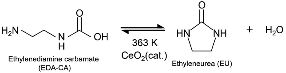 | (2) |
 | (3) |
For the chemistry of EU synthesis, a process scheme was conceptualised for quad-C EU production, as illustrated in Fig. 1. This scheme comprises five main steps for integrating CCU and EU separation from the process, as follows:
Step 1: EDA was injected into the column reactor, whereby some EU molecules were adsorbed onto the CeO2 surface.
Step 2: the CO2-containing feed gas was passed through the reactor, and CO2 was captured in the column through EDA-CA generation (eqn (1)).
Step 3: the reactor was heated to facilitate the chemical reaction (eqn (2)) over the CeO2 catalyst. Consequently, a minor quantity of LU was produced as a by-product.
Step 4: the column was washed with the EDA liquid. The residual liquid in the column was used for CO2 capture and EU synthesis (steps 2–4).
Step 5: pure EU was separated from the EU-rich EDA liquid discharged from the column reactor, and water was removed from the EDA liquid.
 | ||
| Fig. 1 Conceptual process scheme for quad-C EU production. | ||
This scheme strategically combines CO2 capture with EU synthesis and purification to achieve an efficient process flow, amplifying CO2 capture and conversion from the air with a highly CO2-absorbing amine in the reaction unit.33
2.2. Process design and specifications of unit operations
With the conceptualisation of the aforementioned process scheme, this study presents a detailed design of the quad-C EU production process, including chemical separations. Fig. 2 shows a schematic of the quad-C EU production process. The system comprises several components, including a reaction unit, flash separation unit, distillation unit for EU purification, and pressure-swing distillation system. | ||
| Fig. 2 Schematic of the quad-C EU production process. | ||
A fixed-bed type reaction unit was modelled, aligned with our objective of integrating CO2 adsorption with EU synthesis using a CeO2 DFM. A fixed-bed column is typically employed for adsorptive CO2 capture.41,42 The injection of EDA prior to air-loading can enhance the CO2 recovery efficiency because EDA is the amine substance absorbing CO2 from air.43 The reaction unit was equipped with a blower to supply feed air. The operating conditions are listed in Table 1 based on the operational details of the batch reaction system provided by Fujii et al.11
| Reaction time [h] | 4.8 | |
| Conversion (EDA-CA basis) [%] | 52 | |
| Selectivity [%] | EU | 95 |
| LU | 4.6 | |
In addition to the process scheme described above, a rinse gas was introduced from the flash separation stage into the column prior to Step 3. This is because the high-temperature operation in the flash separation system facilitates the decomposition of EDA-CA, producing nearly pure CO2 gas. Fig. 3 shows the cyclic operation procedure for the column reactor, followed by the process scheme explained in Section 2.1. Although the air purge with the injection of the rinse gas (CO2-rich) is described in Fig. 3, the process modelling in this study did not consider the air purge due to the lack of data for simulation. This study assumed that the CO2 content in the rinse gas was fully converted to EDA-CA, which was completely dissolved in the EDA liquid. The effect of the air purge on mass balance and energy analysis is considered to be negligible since CO2 is the dominant chemical in the rinse gas and is fully dissolved in the liquid phase in the form of EDA-CA. The process flow diagram simulated in Aspen Plus is shown in Fig. S1.†
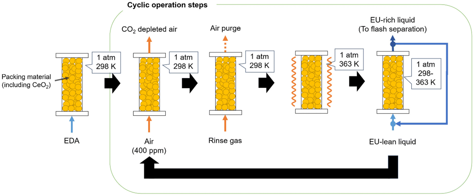 | ||
| Fig. 3 Operating procedure of the reaction unit. | ||
In CO2 recovery from ambient air using a blower, the pressure of the incoming air should be increased to compensate for the pressure drop through the column, which was determined using Ergun's equation:44
 | (4) |
This equation was used in process simulations that considered the pressure drop, air conditions, and CO2 recovery efficiency. The study assumed a fixed amount of CO2 recovered by EU synthesis and determined the feed air flow rate based on the CO2 recovery efficiency. The baseline operating conditions for air-loading are listed in Table 2. The parameters of the CeO2 particles were identical to the experimental parameters reported by Fujii et al.11 The air viscosity was calculated using Aspen Plus V11 at 25 °C and 1 atm.
This study considered flash separators for generating CO2-rich, EU-lean, and EU-rich streams. The flash separation system consists of four separators as shown in Fig. 4. In Flash 1, the EDA liquid discharged from the column reactor was heated up to 160 °C to decompose EDA-CA in the liquid into EDA and CO2,45 and EDA-CA decomposition and flash separation were simulated using the Rstoic model simultaneously. By cooling the vapour stream from the first separator, CO2-rich gas was eventually generated in Flash 3. The liquid stream of the first separator had a higher EU concentration than the vapour stream. Subsequently, this stream was injected into another separator to separate EU from the EDA liquid. Table S1† presents the operating conditions of the flash operating system.
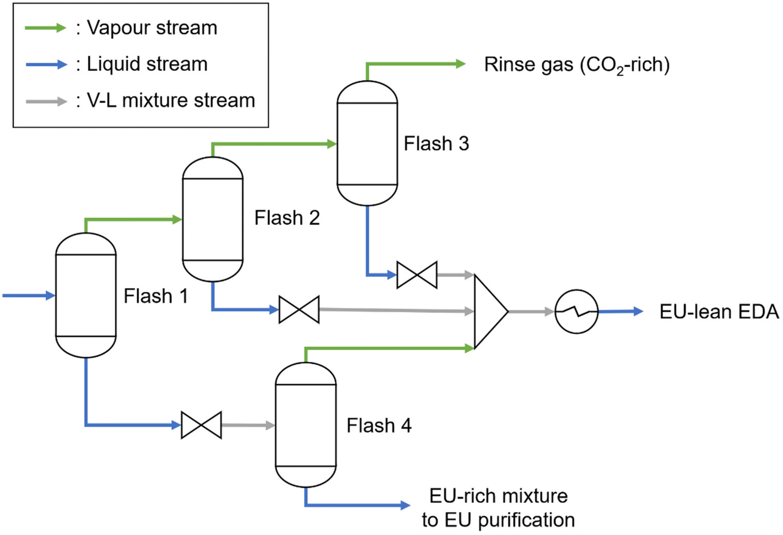 | ||
| Fig. 4 Process flow diagram of the flash separation system. | ||
The EU-rich liquid from the flash separation was further distilled, obtaining high-purity distillation-separated EDA and a mixture of EU and LU. More than 99 wt% EU was separated from ∼97 wt% LU. Fig. 5 shows the operating conditions for EU purification. The EU produced in this process was considered to have commercial purity according to the EU market analysis report.34 The operating conditions of the distillation columns are presented in Table S2.†
 | ||
| Fig. 5 Process flow diagram of the distillation columns for EU purification. | ||
Pressure-swing distillation was employed, as shown in Fig. 6, because of the azeotropic point of the mixture of EDA and water under the given operating conditions, which enabled the efficient use of EDA as the reactant. The purified EDA was recycled to an EU-lean liquid. It was demonstrated that the water and EDA generated in pressure-swing distillation exceeded 99 mol%. Details of the specification for the pressure-swing distillation system are provided in the ESI.†
 | ||
| Fig. 6 Process flow diagram of the pressure-swing distillation columns. | ||
2.3. Process simulations
This study used Aspen Plus V11 and the Wilson activity coefficient model to simulate the thermodynamic behaviour in the process simulations. A steady-state simulation was employed; however, CO2 adsorption involves a non-steady-state process, which is the cyclic operation of the reaction unit. By normalising the EU-lean and EU-rich liquids through liquid storage and mixing, a negligible variation in the liquid flow composition can be achieved, resulting in a stable connection with continuous distillation operations for EU purification and water removal.As Aspen Plus does not have property data for EDA-CA, EU, and LU, the boiling temperatures of EU at atmospheric pressure were retrieved from the literature46 and the pure component properties for EDA-CA and LU were estimated using the Aspen Plus built-in estimator (R-PSE). Process simulations were performed using a conceptual design and addressed a variety of process parameters.
The overall process simulation was divided into three parts: the reaction, separation, and air-loading using the blower. The recovered CO2, i.e. the amount of CO2 captured from air, had a flow rate of 100 mol h−1. The recovered CO2 was completely converted into EDA-CA using the EDA liquid. For CO2 recovery from ambient air via a blower, this study assumed a 50% CO2 recovery efficiency at a baseline condition of 25 °C and vapour pressure of 1.53 kPa, reflecting the climatic conditions of the Kanto region.47 This initial assumption was pivotal for simulating whether a quad-C concept with an ambient-air CO2 recovery could serve as an energy-saving process compared to the EU production from pure EDA and CO2 as raw materials, and the effect of process simulation and energy consumption for EU production on varying CO2 recovery conditions was investigated, as detailed in Subsection 2.5.
The flow rate of the EDA liquid was set to achieve an EDA-CA/EDA ratio of 9.2 mol%, according to the reaction procedure by Fujii et al.11 In this study, all chemical reactions were modelled using the stoichiometric reactor model (Rstoic) due to the lack of equilibrium and kinetic data. The impact of the recycled EU-rich liquid ratio (RLR), ranging from 0.1 to 0.9, was investigated because a portion of the EU liquid was expected to remain in the column after washing the reaction column. The RLR was defined as the fraction of the EU-rich liquid in the column that was not discharged into the flash separation. EU and other products were concentrated when operated at a high RLR.
All distillation columns were simulated using the rigorous distillation model. The purity specified in the process design (H2O: 99 mol%, recycled EDA: 99 mol%, EU: 99 wt%, LU: 99 wt%) was achieved by determining the reflux ratio and distillate flow rate for a given operating condition.
2.4. Energy analysis for EU production
In this study, foreground energy consumption associated with EU production was quantified. Foreground energy consumption was divided into three categories: mechanical work, heat duty, and cooling duty. As electrical energy is the primary source of both mechanical work and heat supply in renewable chemical production, the total energy consumption for the quad-C EU production process (Etot,quad-C, unit in MJ per kg-EU) was determined by summing the mechanical work and heat duties calculated from results of the process simulations, as formulated in eqn (5).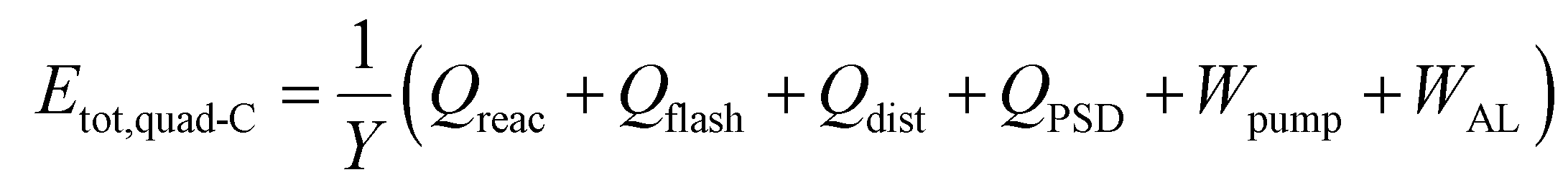 | (5) |
The isentropic efficiency of the pressure-changing equipment, such as pumps, blowers, and compressors, was set at 85%. For the heat duty of the energy equipment, this study assumed that these devices incur negligible energy losses based on the typical thermal efficiency of electrical boilers, which ranges between 99% and 100%. The mechanical work of the blower was calculated based on the pressure drop and ambient air required for EU production. The air-loading time was assumed to be identical to the reaction time (4.8 h) based on the operational necessity of using two columns for cyclic operation to ensure continuous production and efficiency of the process.
2.5. Sensitivity analysis of CO2 recovery conditions on the energy requirement for air-loading
The effect of CO2 recovery conditions affecting the pressure drop of CO2 adsorption on the energy requirement for air-loading was quantified using Aspen Plus and a Python numerical solver. Fig. 7 presents the overall picture of the sensitivity analysis for the air-loading specifications. This study constantly assumed that the amount of CO2 used for EU synthesis was 100 mol h−1. When the air-loading time was identical to the reaction time (4.8 h), the pressure drop for the air-loading was determined by the CO2 recovery efficiency and the energy requirement.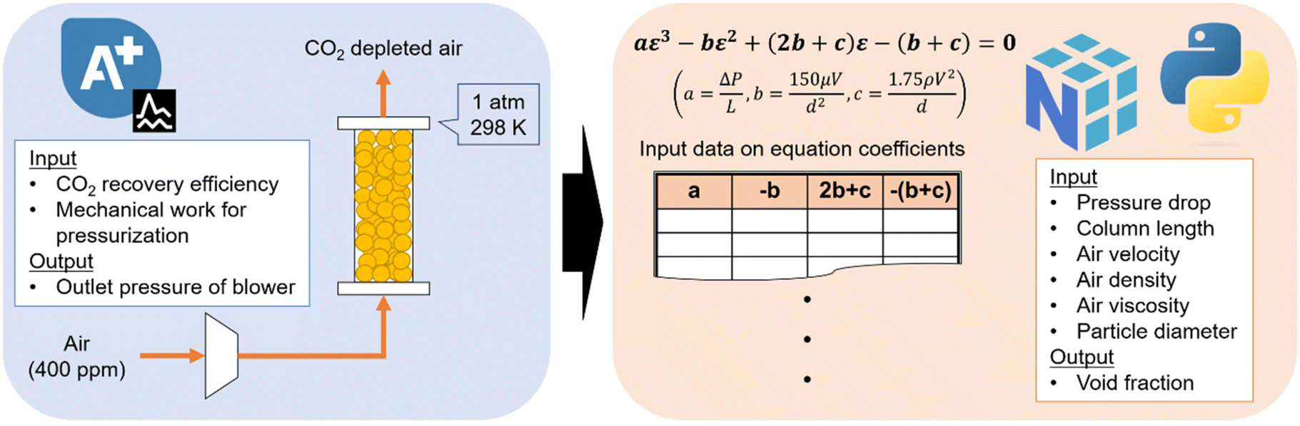 | ||
| Fig. 7 Overall picture of sensitivity analysis by combining Aspen simulation with Python programming. | ||
Aspen Plus was used to quantify the dependency of the CO2 recovery efficiency on the energy and pressure requirements for the air-loading. The pressure drop needed to load the air to provide 100 mol h−1 of CO2 was calculated by setting the values of the CO2 recovery efficiency and energy requirement for the air-loading. As simulated above, the isentropic efficiency of the blower was unchanged from the benchmark, which was 85% for this study. The detailed procedure of the Aspen simulations for the sensitivity analysis is provided in the ESI.†
As shown in eqn (4), Ergun's equation is typically used to estimate the pressure drop for the air-loading. By decomposing eqn (4), the parameters characterising the column operation can be calculated by inputting values of the pressure drop obtained in Aspen simulations. Among the parameters characterising the air-loading operation, the void fraction of the CeO2 dual-functional material appears to be the most challenging to estimate as the CO2 capture mechanism in the quad-C process design is considered complex due to the combination of adsorption on CeO2 surface and absorption with EDA.
For the above reasons, a cubic equation with the void fraction as a variable was formulated by decomposing Ergun's equation as follows:
 | (6) |
NumPy library (version 1.24.3)48 was used to solve eqn (6) in a Python environment (version 3.8.8). The input data of each equation coefficient were created, and the cubic equation was solved numerically. Details of the Python program are provided in the ESI.†
2.6. Analysis of the cost of raw materials and energy for EU production
The commercial process for EU production converts EDA and urea into EU with the ethylene glycol solvent, as shown in eqn (7), which creates ammonia as a by-product.34 | (7) |
According to the market report,34 in the existing EU production process, raw materials and energy consumption account for 89.3% of the total EU production cost. Moreover, acquiring cost data on chemical equipment used in the quad-C processes is challenging due to the early-stage process assessment; the quad-C process was not substantially complex compared to the process configuration of the conventional EU production.34 Here, the cost of raw materials and energy for quad-C EU production (CRE, unit in USD per kg-EU) is defined as the economic indicator by the following equation:
 | (8) |
This study assumed three cases for EU production to investigate the effect of introducing the quad-C process concept as follows:
• Case I: conventional process, as shown in eqn (7).
• Case II: Quad-C process using CO2 from the ambient air (CDAC = 0, WAL: variable).
• Case III: CeO2-based EU production process using pure CO2 from a DAC system (CDAC: reference data,49WAL = 0).
This study assumed that all energy supply for EU production was provided with electricity for simplicity. All the cost data were fixed on the 2023 fiscal year basis according to the Chemical Engineering Plant Cost Index (CEPCI).50 The ESI† elaborates on the details of the cost analysis.
3. Results and discussion
3.1. Mass balance of process simulations
In this study, all process simulations successfully converged without mass balance errors or specification violations. Fig. 8 shows the mass balance of the quad-C EU production for a CO2 recovery efficiency of 50% and RLR of 0.5. The EDA makeup stream was maintained at 110 mol h−1 for all the simulation cases, whereas the CO2 flow rate was 100 mol h−1. The flow rate of the EDA makeup compensates for any losses due to purging and minor leakages in the effluent and in the EU and LU product streams. Notably, the purge stream in the EU liquid was less than 5 mol h−1, representing approximately 4.5% of the make-up stream, which reduced the economic and environmental impact of the purge stream on EU production. | ||
| Fig. 8 Mass balance of the quad-C EU production for 50% CO2 recovery efficiency and 0.5 RLR. | ||
The required flow rate of ambient air was calculated to be 1762.43 kg for 1 kg EU produced. This flow rate is significantly higher than that of other process streams because of the low CO2 concentration (400 ppm) in the ambient air. With 0.53 kg CO2 recovered for 1 kg EU produced, the CO2 recovery efficiency is a key factor affecting the amount of air required for EU production. Therefore, controlling the CO2 recovery efficiency is an important consideration in the development and optimisation of this process.
3.2. Foreground energy consumption for EU production
Fig. 9 shows the energy consumption of EU production at varying RLRs. At lower RLRs, the flash separation process is the most energy-intensive step. This is because flash separation decomposes EDA-CA and evaporates EU-lean liquid with an EDA-CA/EDA ratio of 9.2 mol%. By increasing the RLR, energy consumption was drastically reduced in the flash separation step. When the RLR exceeded 0.6, pressure-swing distillation becomes the primary energy-consuming step because of the lower amount of required EU-lean liquid and the consistent discharge of the process water generated in the EU synthesis. Air-loading did not substantially affect the total energy consumption because of the high void fraction in the reaction column, as shown in Table 2. Meanwhile, the mechanical work for the blower might vary in the case of a high RLR because the void space of the reaction unit could be occupied by the residual liquid. Therefore, the change in the operating conditions for air-loading should be carefully evaluated to manage the total consumption because the void fraction and air for CO2 recovery are susceptible to the mechanical work of the blower. | ||
| Fig. 9 Energy consumption for EU production at different RLRs. Note: Sep.: separation, Dist.: distillation, PS: pressure swing. The CO2 recovery efficiency was 50% for all RLRs. | ||
3.3. Energy requirement for air-loading under varying CO2 recovery efficiency and column operations
Fig. 10 depicts the energy requirements for air-loading under various operating conditions for the CO2 recovery step. The air-loading in the quad-C (CO2 recovery efficiency: 50%; other conditions are given in Table 2) and the conventional DAC system consume 1.99 and 8.81 MJ per kg-CO2,18 respectively. These energy requirements correspond to 1.06 and 4.69 MJ per kg-EU according to the mass balance shown in Fig. 8, as the amount of CO2 required for producing 1 kg of EU is 0.53 kg. This figure clearly illustrates how various operational factors affect the energy requirements for air-loading. The void fraction of the DFM should be consistently more than 0.5 to make CO2 capture more energy-efficient than that of the conventional DAC system. In the case of the 5 m column, the void fraction should be more than 0.90, which is a high threshold for CO2 adsorbents considering that those in previous studies have ranged from 0.109 to 0.93.51–53 The second term of eqn (4) is proportional to the square of the air velocity; thus, the air velocity significantly influences the energy requirement for air-loading. | ||
| Fig. 10 Equal-energy curves required for air-loading under various operating conditions for CO2 recovery. Note: Baseline condition has 50% and 0.85 for CO2 recovery efficiency and void fraction, respectively. | ||
Consequently, this study successfully assessed the effect of the CO2 recovery efficiency on the operating conditions for the air-loading by combing Aspen simulations with external programming. The results of the sensitivity analysis offer crucial insights into column design and process parameters for quad-C operations. The void fraction of the DFM should be more than 0.5 to maintain a low energy consumption compared to the conventional DAC system. When a reaction column needs a long length for CO2 recovery, the air velocity should be reduced, and the column should have a large cross-sectional area to maintain a low energy consumption for the air-loading and the amount of recovered CO2.
3.4. Cost of raw materials and energy for EU production
Fig. 11 represents the cost comparison of raw materials and energy for EU production between conventional (Case I) and quad-C (Case II) EU processes at varying RLRs and cost of electricity under the baseline operating condition for air-loading (50% and 0.85 for CO2 recovery efficiency and void fraction, respectively). The blue area illustrates the foreground energy consumption for Case II, indicating that a higher RLR can maintain its economic advantage over Case I owing to lower energy consumption, regardless of electricity costs. Unlike Case I, utilising urea, Case II employs CO2 as a raw material, potentially reducing raw material costs for EU production through process intensification in the quad-C system. Moreover, substituting urea with renewable CO2 from the air can drastically contribute to the GHG mitigation associated with EU production since the existing urea production is an energy-intensive and GHG-emitting process.54 | ||
| Fig. 11 Cost comparison of raw materials and energy for EU production between conventional and quad-C EU processes at varying RLRs. Note: The red line indicates the cost of raw materials and energy for conventional EU production. The air-loading in the quad-C process was operated with the baseline condition (50% and 0.85 for CO2 recovery efficiency and void fraction, respectively). | ||
Therefore, the cost reduction through the quad-C process intensification from the conventional process is primarily driven by the substitution of the raw material. Simultaneously, the quad-C process can serve as a process intensification approach to reduce both foreground and background energy consumption using ambient CO2 without sorbent regeneration instead of fossil-based urea. This shift has a great potential to decrease life-cycle GHG emissions associated with EU production. Meanwhile, the scale-up for the quad-C process does not substantially reduce the capital cost; this is because a long column length incurs a large mechanical work for air-loading, and the numbering-up approach for the reaction unit is energy-efficient, which generally does not reduce the proportion of capital cost in the total production cost. Furthermore, this study did not account for the treatment of exhaust gas and waste streams, which can offset the economic and environmental benefits of energy-saving and raw material substitution through the quad-C process in the case of a large leakage of EDA.
The cost difference between the quad-C process (Case II) and the CeO2-based process using pure CO2 from DAC systems (Case III) is shown in Fig. 12, with a fixed RLR of 0.5 for both cases. The blue lines indicate the cost of raw materials and energy for EU production, and the green area is the range of DAC cost reported by IEA.49 For example, in the case of 230 $ per t-CO2 spent on DAC operations, the cost of raw materials and energy for EU production becomes equivalent between both cases when the cost of electricity and energy requirement for air-loading are 0.01 $ per MJ and 16.38 MJ per kg-EU, respectively. In Fig. 12, arrows a′, a′′, and a′′′ indicate the scenarios where the quad-C process achieves a lower cost than the DAC-based process, while arrows b′, b′′, and b′′′ represent the opposite, where the DAC-based process is more cost-effective. Since the green area shifts sharply lower as the cost of electricity is higher, the economic preference of Case II over Case III significantly depends on the cost of electricity; this is because this study assumed the foreground energy consumption for EU production is fully provided with electricity. Compared to Case I, shown in the red line of Fig. 12, Case II and III can reduce the cost of raw materials and energy for EU production as the cost of renewable electricity is 0.033 $ per MJ, the maximum reported value by IRENA.55 As illustrated in Fig. 10, the energy break-even point at which the quad-C process loses its energy-saving advantage over the DAC-based process is 4.69 MJ per kg-EU. When the quad-C process can access lower-cost electricity, it has greater economic potential due to the integration of CO2 capture and utilisation. Conversely, if electricity is expensive and a low-cost DAC system supplies CO2, the DAC-based process may become more economically viable than the quad-C approach. Notably, IEA's estimates are based on large-scale DAC applications, which still position DAC as the most expensive source of CO2. Conversely, the risk tolerance for the investment in a quad-C process can be reduced compared to DAC-based processes since the quad-C process can directly produce a highly value-added chemical.
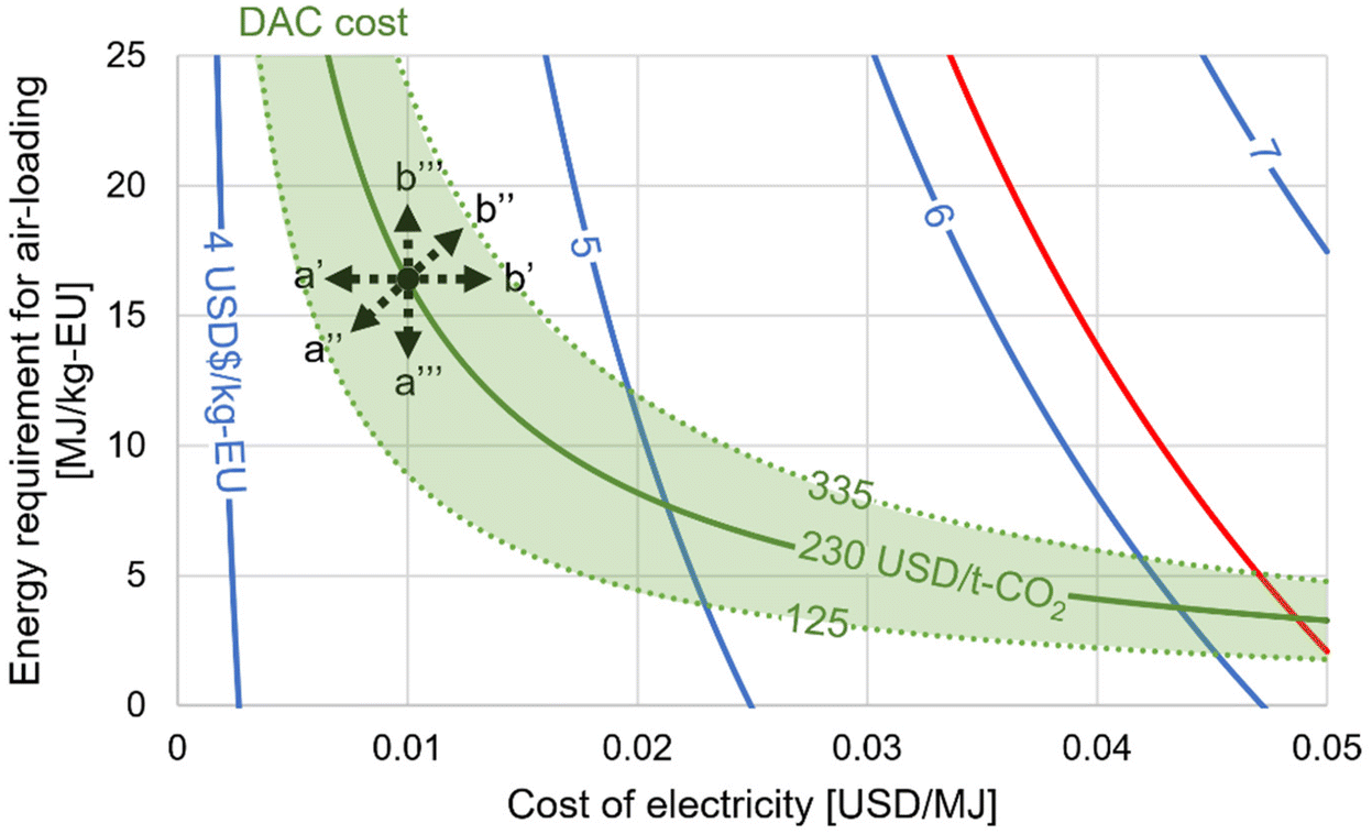 | ||
| Fig. 12 Equal-cost curve of raw materials and energy for EU production between quad-C and CeO2-based EU processes at varying costs of electricity and energy requirement for air-loading. Note: The RLR was fixed to 0.5 in both processes. Blue lines indicate the cost of raw materials and energy for EU production. The green area is the range of DAC cost in the IEA report. The red line indicates the cost of raw materials and energy for conventional EU production. | ||
Consequently, the quad-C process approach has various economic advantages over the CeO2-based process using pure CO2 from DAC systems. The economic viability of the quad-C approach is significantly influenced by advancements in DAC and renewable energy technologies. This study assessed the cost of raw materials and energy for EU production as an economic indicator. The equipment sizing and cost of the CeO2 DFM should be essential to consider the detailed economic comparison between the quad-C process and the CeO2-based process using pure CO2; this is because a low CO2 recovery efficiency inevitably increases the reactor size and amount of the DFM required to capture 100 mol h−1 of CO2, while the CeO2-based process using CO2 does not need to change the reactor size due to the constant inlet flowrate at a given RLR.
4. Exploration of process intensification from conceptual process design
This section explores potential strategies for process intensification in the quad-C EU production process. Specifically, two types of process intensification are considered: (1) using an air dryer for additional water removal in the reaction column and (2) reducing the amount of EDA liquid required for EU synthesis.4.1. Air drying in the reaction column
The air-drying step was integrated into the column operation, positioned between the EU synthesis and column washing stages, as depicted in Fig. 3. The procedure for the reaction unit operation with air-drying is depicted in Fig. S5.† The operating condition for the air-drying process was set as follows: wet air (after the air-drying step in the column) with a relative humidity of 10% at 100 °C. The flow rate of water used in the air dryer was determined based on the operational conditions outlined in the process design of the column reactor. Consequently, the airflow rate for air-drying was adjusted based on the air-drying ratio (AR), relative humidity, and fixed operating conditions of the column reactor.
The dry air produced in the dryer was assumed to be recyclable for the subsequent air-drying operations because only water was enriched during the drying step. For simplicity, no other chemicals, except water, were discharged from the column reactor during air-drying because only water reached its boiling point at 100 °C, whereas CO2 was fully converted into EDA-CA in the capturing reaction and EDA-CA decomposition did not occur in the EU synthesis.
The schematics of the air dryer and its operating procedures for the air dryer are shown in Fig. 13 and 14. In this setup, wet air is compressed to 1.6 atm, and water is separated in the first flash separator. After the first water removal, electrical energy is recovered using an expander. Subsequently, additional water is removed from the air as the temperature drops to approximately 1 °C due to the expansion. The dry air with a relative humidity of less than 1% at 100 °C is then supplied back to the column and heated in the second flash separator with heat recovery. This cyclical process aims to enhance the efficiency of the air-drying step and promote overall energy savings in the quad-C EU production process.
 | ||
| Fig. 13 Schematics of the quad-C EU production process with an air dryer. | ||
 | ||
| Fig. 14 Operating procedure for the air dryer. | ||
 | ||
| Fig. 15 Mass balance of the quad-C EU production with CO2 recovery efficiency: 50%, AR: 0.5, and RLR: 0.5. | ||
The substantial reduction in water content within the EU-lean liquid after installing the air-drying step indicates a notable shift in the operating conditions for the liquid recycle compared with the mass balance of the entire process in the benchmark scenarios. Therefore, this process modification is expected to result in significant energy savings. Further, the decrease in water content in the EDA liquid not only impacts the efficiency of the liquid recycle but also has broader implications for the overall energy efficiency of the quad-C EU production process. The role of water in impeding the equilibrium reaction for EU synthesis underscores the critical importance of integrating an air dryer into the process. In particular, the inclusion of an air dryer facilitates EU synthesis with minimal process modification and effectively enhances the process efficiency by lowering the water content, which can inhibit the reaction equilibrium.
Concurrently, the volatility of EDA and substrate in the EU synthesis should be considered. Although EDA inherently exhibits volatility and some EDA leakage is expected during the air-loading process, its volatility has been shown to be significantly mitigated in the presence of water.56 Therefore, controlling the AR is a key factor in the design of the quad-C EU production process, especially from an environmental standpoint. In particular, balancing the water removal to optimise the EU synthesis while minimizing EDA volatility and potential environmental impact is essential for achieving a sustainable and efficient production process.
 | ||
| Fig. 16 Total energy consumptions of the quad-C EU production under various operation parameters. Note: Sep.: separation, Dist.: distillation, PS: pressure swing, RLR: recycled EU-rich liquid ratio. CO2 recovery efficiency was 50% for all RLRs and ARs. | ||
The conventional DAC system consumes an energy of 8.81 MJ per kg-CO2,18 including the desorption energy required to derive purified CO2, corresponding to 4.69 MJ per kg-EU, according to the mass balance as shown in Fig. 15. Meanwhile, the quad-C process demonstrated a significant reduction in energy consumption for air loading. Assuming a 50% CO2 recovery efficiency, 0.5 AR, and 0.5 RLR, the air-loading process in the quad-C process requires a mechanical work of 1.06 MJ per kg-EU when utilizing a blower. This is considerably lower than that of the DAC system, as it eliminates the need for energy consumption in the desorption step.
The current quad-C process was conceptually designed by using parameters from batch experiments, and it involves a total energy consumption of 25.14 MJ per kg-EU. In the future, a continuous-flow reaction system with multiple rotational reaction units can be developed and adopted for the quad-C process to achieve higher conversion rates and EU yields than batch systems.11 and further energy savings from integrating CO2 capture and utilisation into the quad-C process might be achieved. Consequently, further process simulations are warranted to accurately quantify the energy-saving effects of the quad-C process, considering the differences in the reaction systems used.
4.2. Effect of EDA liquid required for EU synthesis on energy consumption
Fig. 17 shows the energy-saving effect of decreasing the amount of EDA liquid, i.e., increasing the EDA-CA/EDA ratio, required for EU synthesis. With an RLR of 0.1, the increase in EDA-CA concentration promotes energy saving. This energy-saving trend remained effective even at an RLR of 0.5, whereas the increased EDA-CA concentration did not significantly decrease the energy required for EU production at an RLR of 0.9. When the molar ratio of EDA-CA/EDA was increased to 0.2 and 1.0, specifically in scenarios with AR and RLR of 0.5, the total energy consumption for EU production decreased substantially. Consequently, the energy requirements could be reduced to 17.00 and 11.31 MJ per kg-EU, respectively. These decrements represent significant improvements in energy efficiency compared with that of conventional methods. | ||
| Fig. 17 Total energy consumption for EU production at varying EDA-CA concentration prior to the EU synthesis reaction with RLRs of 0.1, 0.5, and 0.9. Note: AR: air-drying ratio, RLR: recycled EU-rich liquid ratio. CO2 recovery efficiency was 50% for all RLRs and ARs. | ||
Compared with conventional CCU-based EU production, the quad-C process design offers a more energy-efficient approach. It should be noted that all simulation results were obtained at 50% CO2 recovery efficiency and the air-loading conditions listed in Table 2. Any process intensification strategy can affect the operating conditions for CO2 recovery, including the void fraction and CO2 recovery efficiency, as discussed in the sensitivity analysis in Subsection 3.3. Thus, the combined use of air-drying technology and decrement in EDA liquid usage contributes to increasing the energy efficiency when considering other operational factors for CO2 recovery. These intensification approaches can further reduce the energy cost for EU production, making the quad-C process superior to the conventional EU process from an economic perspective. Other energy-saving technologies can be introduced in the quad-C process design, such as crystallisation, since the EU solubility in the EDA substantially changes in the operating temperature range of the quad-C process.57
5. Conclusion
This study modelled and assessed a quad-C process that integrates CO2 adsorption and EU synthesis. The conceptualisation and process design of the quad-C scheme were tailored for EU synthesis using CeO2 as a DFM. Subsequently, process modelling was performed, and simulation results were obtained based on early-stage experimental studies. The quad-C process design can effectively reduce the energy consumption and cost of raw materials and energy for EU production due to the direct use of CO2 from the ambient air instead of urea, which is a raw material for the existing commercial EU production.The effectiveness of process intensification strategies was assessed by keeping the conceptual design as the benchmark. In particular, the impact of integrating additional water removal technologies and reducing the amount of EDA liquid required for EU synthesis were evaluated. Retrofitting air-drying technology was demonstrated to be an effective process intensification strategy, resulting in significant energy savings, even at low ARs. This finding is crucial for designing processes that require chemical water removal. Furthermore, using less liquid in EU synthesis has emerged as a viable method for designing energy-efficient processes.
The incorporation of air-drying and EDA liquid reduction in the quad-C process further decreased energy consumption for EU production. Therefore, the proposed combination of process improvements can significantly enhance the environmental and economic potential of the process. Moreover, the findings clearly indicate the value of early-stage process modelling and assessment for the efficient development of CO2-based chemistry processes. Meanwhile, the energy requirement for air-loading can reduce the energy efficiency of the quad-C system with a low void fraction and CO2 recovery efficiency; therefore, the CO2 recovery step should be considered in future experimental studies. In future works, further process simulations are warranted to accurately quantify the energy-saving effects of the quad-C process considering the differences in the reaction systems used and constructing heat exchanger networks.
Abbreviations
| AR | Air-drying ratio |
| CCU | Carbon capture and utilisation |
| CCUS | Carbon capture, utilisation, and storage |
| DAC | Direct air capture |
| DFM | Dual-functional material |
| EDA | Ethylenediamine |
| EDA-CA | Ethylenediamine carbamate |
| EU | Ethyleneurea |
| GHG | Greenhouse gas |
| LU | Linear urea |
| quad-C | Combined carbon capture and conversion |
| RLR | EU-rich liquid ratio |
Symbols
| ΔP | Pressure drop of reaction unit (unit in Pa) |
| L | Column depth (unit in m) |
| μ | Fluid viscosity (unit in Pa s) |
| ε | Column void fraction |
| V | Flow velocity (unit in m s−1) |
| d | Particle diameter (unit in m) |
| ρ | Particle density (unit in kg m−3) |
| E tot,quad-C | Total energy consumption for the quad-C EU production (unit in MJ per kg-EU) |
| Y EU | Hourly EU production volume (unit in kg-EU per h) |
| Q reac | Heat duty in reaction unit (unit in MJ h−1) |
| Q flash | Heat duty in flash separation (unit in MJ h−1) |
| Q dist | Heat duty in distillation for EU purification (unit in MJ h−1) |
| Q PSD | Heat duty in pressure-swing distillation (unit in MJ h−1) |
| W pump | Electricity consumption in pump (unit in MJ h−1) |
| W AL | Electricity consumption for air-loading (unit in MJ h−1) |
| a | Coefficient of sensitivity analysis |
| b | Coefficient of sensitivity analysis |
| c | Coefficient of sensitivity analysis |
| C RE | Cost of raw materials and energy for the quad-C EU production (unit in USD per kg-EU) |
| F EDA | EDA flowrate (kg h−1) |
| F CO2 | CO2 flowrate (unit in kg h−1) |
| C EDA | EDA cost (unit in USD per kg) |
| C DAC | Pure CO2 cost from a DAC system (unit in USD per kg) |
Data availability
The data and programme code supporting this article have been included as part of the ESI.†Conflicts of interest
There are no conflicts of interest to declare.Acknowledgements
This work was partially supported by the Moonshot Research and Development Program (JPNP18016), commissioned by the New Energy and Industrial Technology Development Organization (NEDO), and JST SPRING (Grant Number JPMJSP2114). We would like to thank Editage (https://www.editage.com) for English language editing.References
- IEA, Energy Technology Perspectives 2020, 2020 Search PubMed.
- R. Meys, A. Kätelhön, M. Bachmann, B. Winter, C. Zibunas, S. Suh and A. Bardow, Science, 2021, 374, 71–76 CrossRef CAS PubMed.
- C. Das Neves Gomes, O. Jacquet, C. Villiers, P. Thuery, M. Ephritikhine and T. Cantat, Angew. Chem., Int. Ed., 2012, 51, 187–190 CrossRef CAS PubMed.
- C. Jeong-Potter and R. Farrauto, Appl. Catal., B, 2021, 282, 119416 CrossRef CAS.
- W. Zhou, K. Cheng, J. Kang, C. Zhou, V. Subramanian, Q. Zhang and Y. Wang, Chem. Soc. Rev., 2019, 48, 3193–3228 RSC.
- A. Kätelhön, R. Meys, S. Deutz, S. Suh and A. Bardow, Proc. Natl. Acad. Sci. U. S. A., 2019, 116, 11187–11194 CrossRef.
- IPCC Special Report on Renewable Energy Sources and Climate Change Mitigation, ed. O. Edenhofer, R. Pichs-Madruga, Y. Sokona, K. Seyboth, P. Matschoss, S. Kadner, T. Zwickel, P. Eickemeier, G. Hansen, S. Schloemer and C.von Stechow, 2012 Search PubMed.
- A. J. J. Straathof and A. Bampouli, Biofuels, Bioprod. Biorefin., 2017, 11, 798–810 CrossRef CAS.
- M. Aresta and M. Galatola, J. Cleaner Prod., 1999, 7, 181–193 CrossRef.
- J. Peng, M. Tamura, M. Yabushita, R. Fujii, Y. Nakagawa and K. Tomishige, ACS Omega, 2021, 6, 27527–27535 CrossRef CAS PubMed.
- R. Fujii, M. Yabushita, D. Asada, M. Tamura, Y. Nakagawa, A. Takahashi, A. Nakayama and K. Tomishige, ACS Catal., 2023, 13, 1562–1573 CrossRef CAS.
- H. Ohno, M. Ikhlayel, M. Tamura, K. Nakao, K. Suzuki, K. Morita, Y. Kato, K. Tomishige and Y. Fukushima, Green Chem., 2021, 23, 457–469 RSC.
- H. Huang, R. C. Samsun, R. Peters and D. Stolten, Green Chem., 2021, 23, 1734–1747 RSC.
- T. Cordero-Lanzac, A. Ramirez, A. Navajas, L. Gevers, S. Brunialti, L. M. Gandía, A. T. Aguayo, S. Mani Sarathy and J. Gascon, J. Energy Chem., 2022, 68, 255–266 CrossRef CAS.
- J. Uebbing, L. Rihko-Struckmann, S. Sager and K. Sundmacher, J. CO2 Util., 2020, 40, 101228 CrossRef CAS.
- P. Tomkins and T. E. Müller, Green Chem., 2019, 21, 3994–4013 RSC.
- K. Yagihara, K. Fukushima, H. Ohno, A. Guzman-Urbina, J. Ni and Y. Fukushima, Int. J. Greenhouse Gas Control, 2024, 132, 104068 CrossRef CAS.
- D. W. Keith, G. Holmes, D. St. Angelo and K. Heidel, Joule, 2018, 2, 1573–1594 CrossRef CAS.
- M. Meijssen, V. Becattini and M. Mazzotti, ACS Sustainable Chem. Eng., 2024, 12, 2709–2718 CrossRef CAS.
- S. Sun, H. Sun, P. T. Williams and C. Wu, Sustainable Energy Fuels, 2021, 5, 4546–4559 RSC.
- M. Liu, L. Liang, X. Li, X. Gao and J. Sun, Green Chem., 2016, 18, 2851–2863 RSC.
- L. Li, Z. Wu, S. Miyazaki, T. Toyao, Z. Maeno and K. I. Shimizu, RSC Adv., 2023, 13, 2213–2219 RSC.
- A. Kumar, R. Bhardwaj and J. Choudhury, ACS Catal., 2023, 13, 927–933 CrossRef CAS.
- N. Guntermann, H. G. Mengers, G. Franciò, L. M. Blank and W. Leitner, Green Chem., 2021, 23, 9860–9864 RSC.
- A. Wotzka, R. Dühren, T. Suhrbier, M. Polyakov and S. Wohlrab, ACS Sustainable Chem. Eng., 2020, 8, 5013–5017 CrossRef CAS.
- K. Takeuchi, H. Koizumi, H. Nagae, K. Matsumoto, N. Fukaya, K. Sato and J.-C. Choi, J. CO2 Util., 2024, 83, 102814 CrossRef CAS.
- Y. Qiao, W. Liu, R. Guo, S. Sun, S. Zhang, J. J. Bailey, M. Fang and C. Wu, Fuel, 2023, 332, 125972 CrossRef CAS.
- V. Nikulshina, N. Ayesa, M. E. Gálvez and A. Steinfeld, Chem. Eng. J., 2008, 140, 62–70 CrossRef CAS.
- C. M. Jens, L. Müller, K. Leonhard and A. Bardow, ACS Sustainable Chem. Eng., 2019, 7(14), 12270–12280 CAS.
- N. McQueen, P. Kelemen, G. Dipple, P. Renforth and J. Wilcox, Nat. Commun., 2020, 11, 3299 CrossRef CAS PubMed.
- J. Wang, R. Fu, S. Wen, P. Ning, M. H. Helal, M. A. Salem, B. B. Xu, Z. M. El-Bahy, M. Huang, Z. Guo, L. Huang and Q. Wang, Adv. Compos. Hybrid Mater., 2022, 5, 2721–2759 CrossRef CAS.
- R. Iwama, K. Takizawa, K. Shinmei, E. Baba, N. Yagihashi and H. Kaneko, ACS Omega, 2022, 7, 10709–10717 CrossRef CAS PubMed.
- M. Tamura, K. Noro, M. Honda, Y. Nakagawa and K. Tomishige, Green Chem., 2013, 15, 1567–1577 RSC.
- Prof Research , 2021 Global and Chinese 2-imidazolidinone (Ethylene urea) industry report, 2021.
- C. Slostowski, S. Marre, P. Dagault, O. Babot, T. Toupance and C. Aymonier, J. CO2 Util., 2017, 20, 52–58 CrossRef CAS.
- W.-F. Kuan, C.-H. Chung, M. M. Lin, F.-Y. Tu, Y.-H. Chen and W.-Y. Yu, Mater. Today Sustain., 2023, 23, 100425 Search PubMed.
- M. Capdevila-Cortada, G. Vilé, D. Teschner, J. Pérez-Ramírez and N. López, Appl. Catal., B, 2016, 197, 299–312 CrossRef CAS.
- P. Anastas and N. Eghbali, Chem. Soc. Rev., 2010, 39, 301–312 RSC.
- A. Yoko, Y. Fukushima, T. Shimizu, Y. Kikuchi, T. Shimizu, A. Guzman-Urbina, K. Ouchi, H. Hirai, G. Seong and T. Tomai, Chem. Eng. Process., 2019, 142, 107531 CrossRef CAS.
- A. F. Ciftja, A. Hartono and H. F. Svendsen, Energy Procedia, 2013, 37, 1605–1612 CrossRef CAS.
- P. A. Argyris, A. Wright, O. T. Qazvini and V. Spallina, Chem. Eng. J., 2022, 428, 132606 CrossRef CAS.
- T. Kinoshita and K. Yogo, Ind. Eng. Chem. Res., 2021, 60, 9906–9914 CrossRef CAS.
- H. Koizumi, K. Takeuchi, K. Matsumoto, N. Fukaya, K. Sato, M. Uchida, S. Matsumoto, S. Hamura and J. C. Choi, Commun. Chem., 2021, 4, 66 CrossRef CAS.
- S. Ergun, Chem. Eng. Prog., 1952, 48, 89–94 CAS.
- Dow Chemical Company, Ethylenediamines: storage and handling, 2001 Search PubMed.
- European Chemical Agency , 2-Imidazolidone: Physical and chemical propertieshttps://echa.europa.eu/registration-dossier/-/registered-dossier/12504/4/4/?documentUUID=b7619b3e-168d-4bf3-a737-9cb62a42f5d7, (accessed December 11, 2023).
- Japan Meteorological Agency , Tables of Monthly Climate Statistics - Climate of Japan, https://www.data.jma.go.jp/obd/stats/data/en/smp/index.html, (accessed January 4, 2024).
- C. R. Harris, K. J. Millman, S. J. van der Walt, R. Gommers, P. Virtanen, D. Cournapeau, E. Wieser, J. Taylor, S. Berg, N. J. Smith, R. Kern, M. Picus, S. Hoyer, M. H. van Kerkwijk, M. Brett, A. Haldane, J. F. del Río, M. Wiebe, P. Peterson, P. Gérard-Marchant, K. Sheppard, T. Reddy, W. Weckesser, H. Abbasi, C. Gohlke and T. E. Oliphant, Nature, 2020, 585, 357–362 CrossRef CAS.
- IEA, Direct Air Capture 2022, 2022 Search PubMed.
- Chemical Engineering, Chemical engineering plant cost index (CEPCI), https://www.chemengonline.com/pci-home, (accessed October 18, 2024).
- R. Stanton and D. J. Trivedi, J. Phys. Chem. Lett., 2023, 14, 5069–5076 CrossRef CAS.
- S. Punpee and C. Phalakornkule, Mater. Today: Proc., 2022, 52, 2517–2522 CAS.
- H. An, B. Feng and S. Su, Fuel, 2013, 103, 80–86 CrossRef CAS.
- C. Mao, J. Byun, H. W. MacLeod, C. T. Maravelias and G. A. Ozin, Joule, 2024, 8, 1224–1238 CrossRef CAS.
- IRENA, Renewable power generation costs in 2023, 2024 Search PubMed.
- World Health Organization, Concise International Chemical Assessment Document: Ethylenediamine, 1999 Search PubMed.
- K. Hiromori, A. Furukawa, A. Takahashi and N. Shibasaki-Kitakawa, J. Chem. Eng. Jpn., 2024, 57(1), 2397992 CrossRef.
Footnote |
| † Electronic supplementary information (ESI) available. See DOI: https://doi.org/10.1039/d4gc04346d |
| This journal is © The Royal Society of Chemistry 2025 |